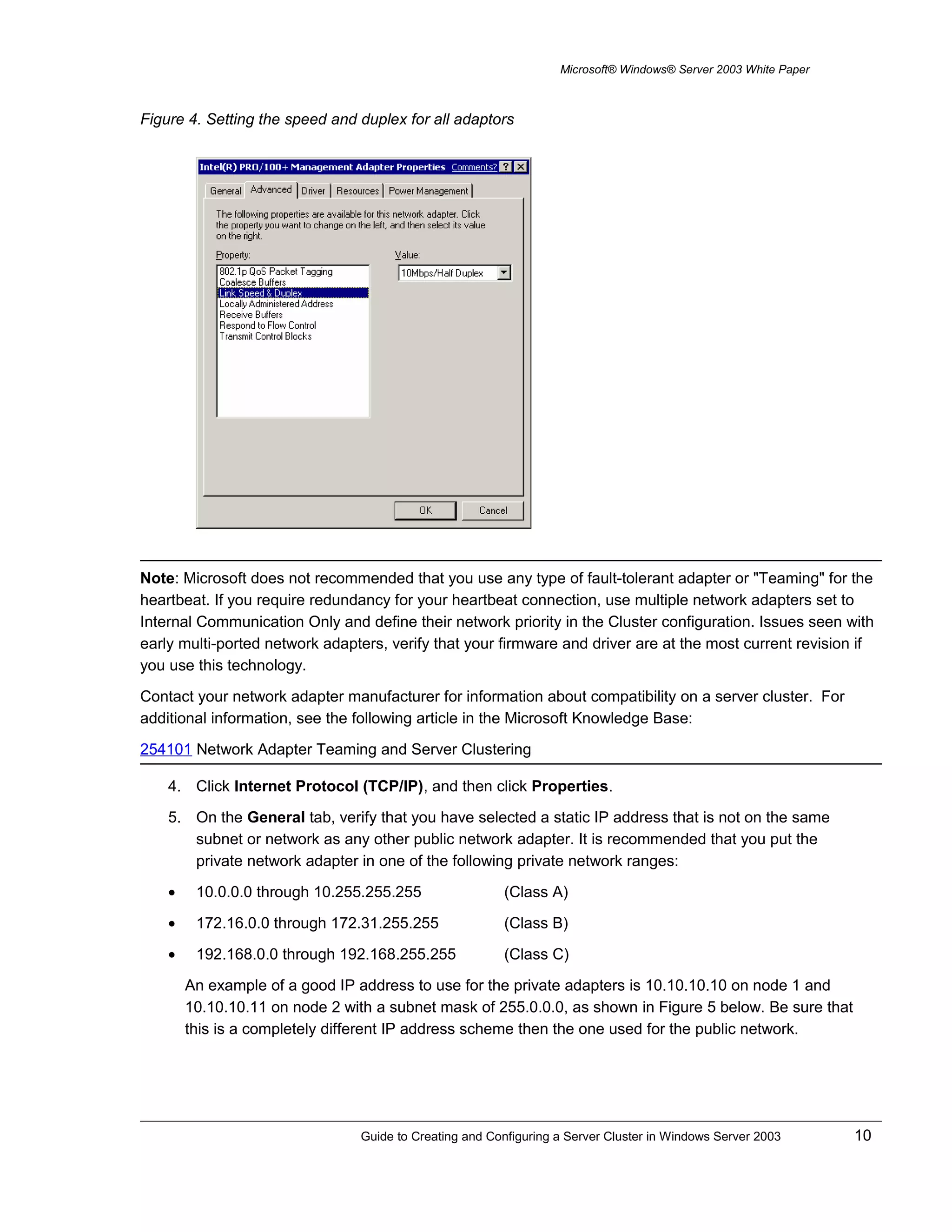
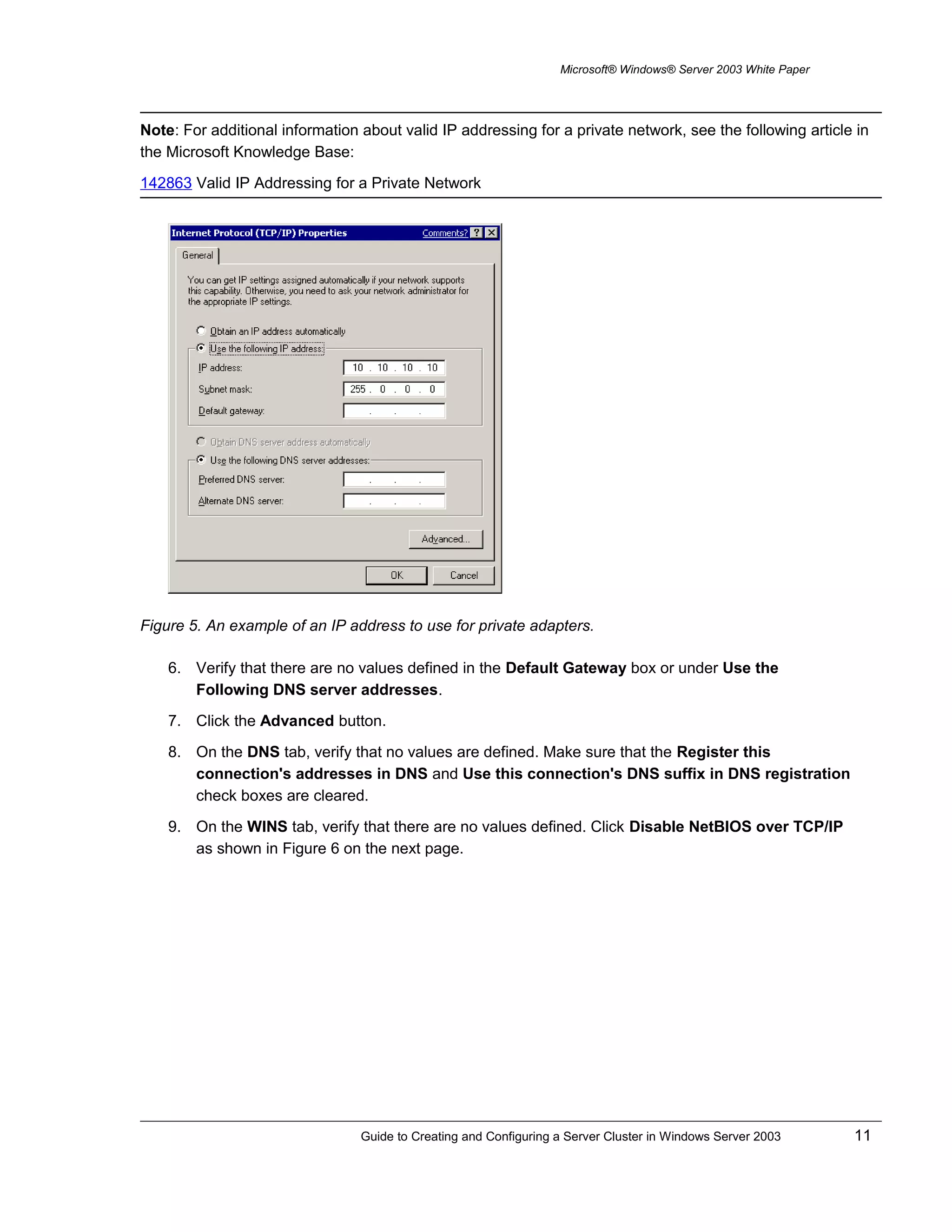
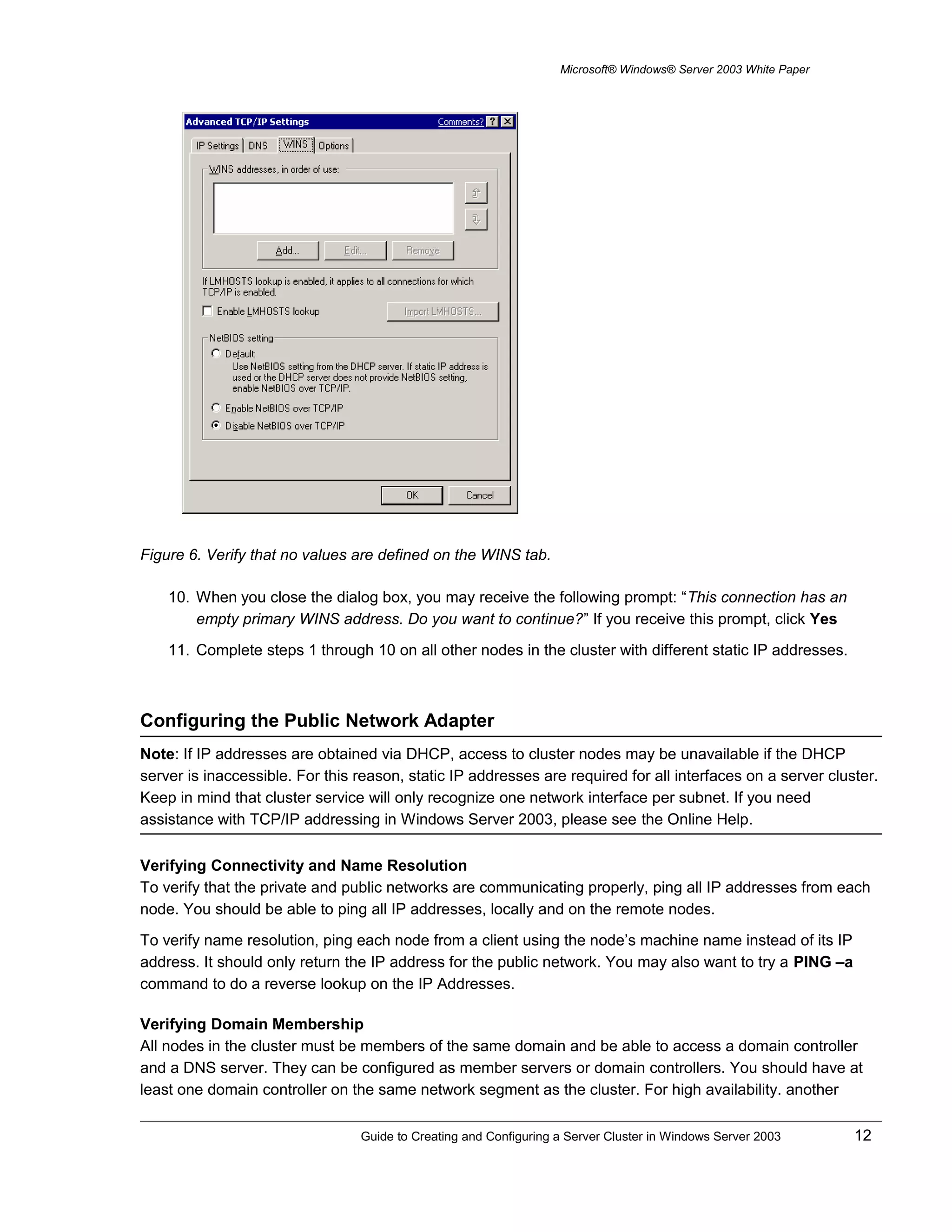
Downloaded 19 times
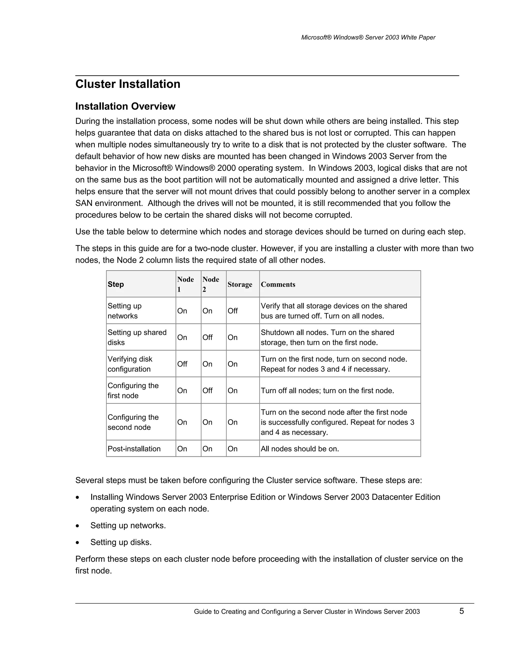

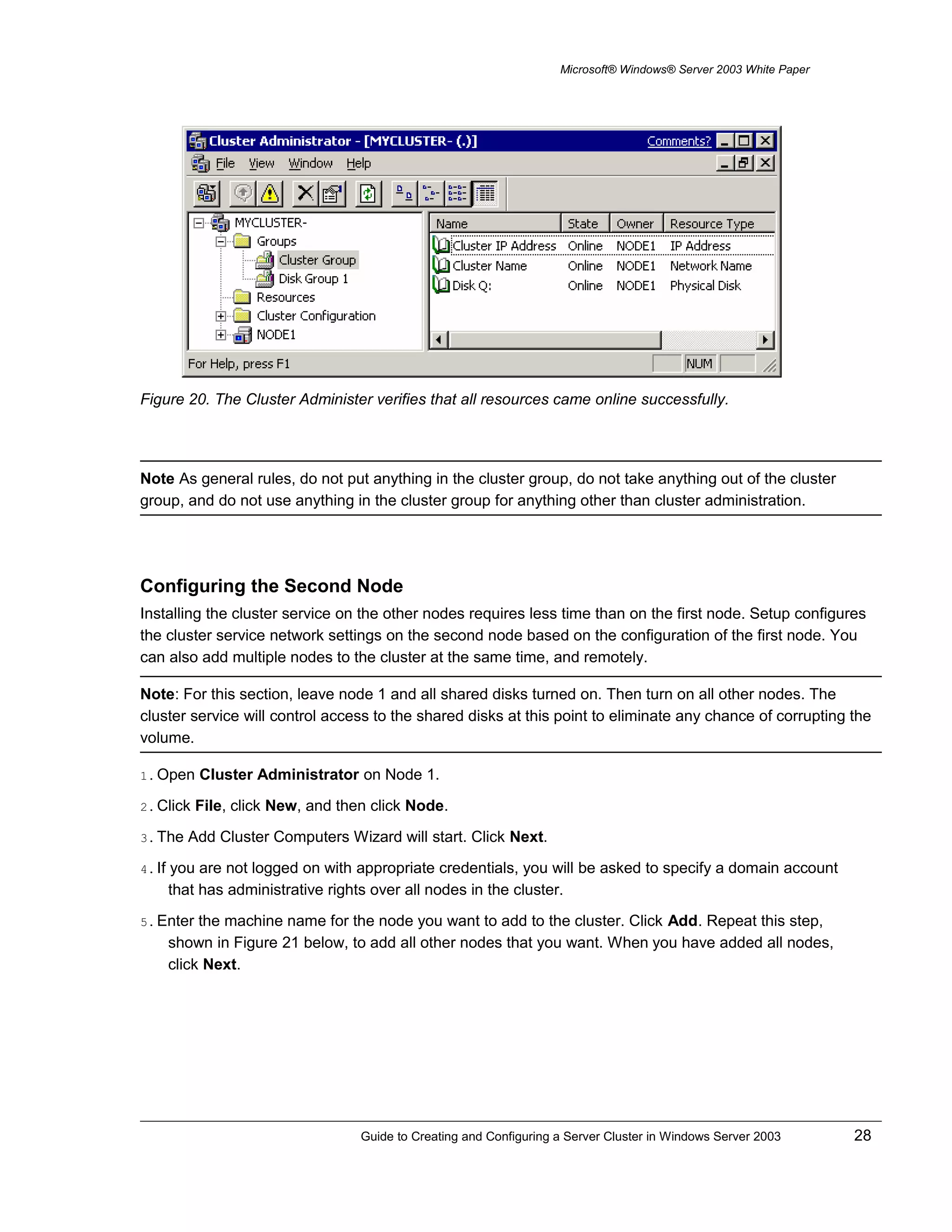

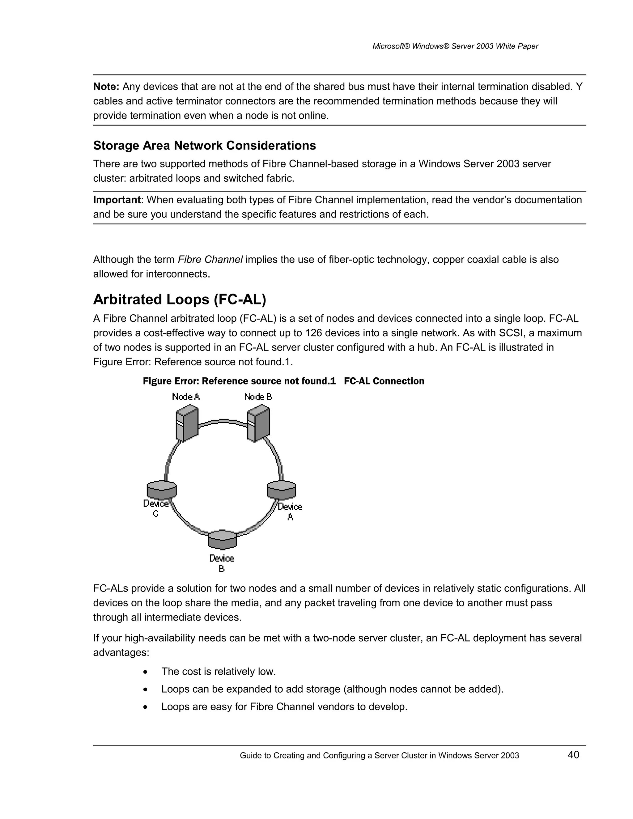
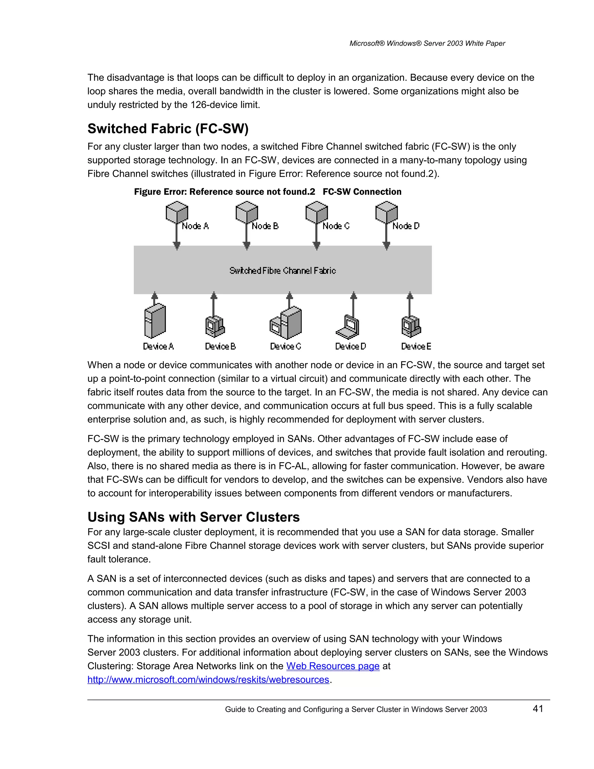

This document provides instructions for creating a two-node server cluster using Windows Server 2003. Key steps include installing Windows Server 2003 on each node, setting up two network adapters per node on separate subnets for public and private communication, configuring shared storage accessible by both nodes, and installing the Cluster Service software while ensuring only one node has access to shared storage at a time. The document outlines hardware and software requirements and provides a checklist to prepare for cluster installation and configuration.


![Victor Jara Habla y Canta [1978]](https://cdn.slidesharecdn.com/ss_thumbnails/victorjarahablaycanta-110303181711-phpapp01-thumbnail.jpg?width=640&height=640&fit=bounds)


![Coded Agents – with UiPath SDK + LangGraph [Virtual Hands-on Workshop]](https://cdn.slidesharecdn.com/ss_thumbnails/codedagentsdeck-251215155422-5497c599-thumbnail.jpg?width=640&height=640&fit=bounds)


