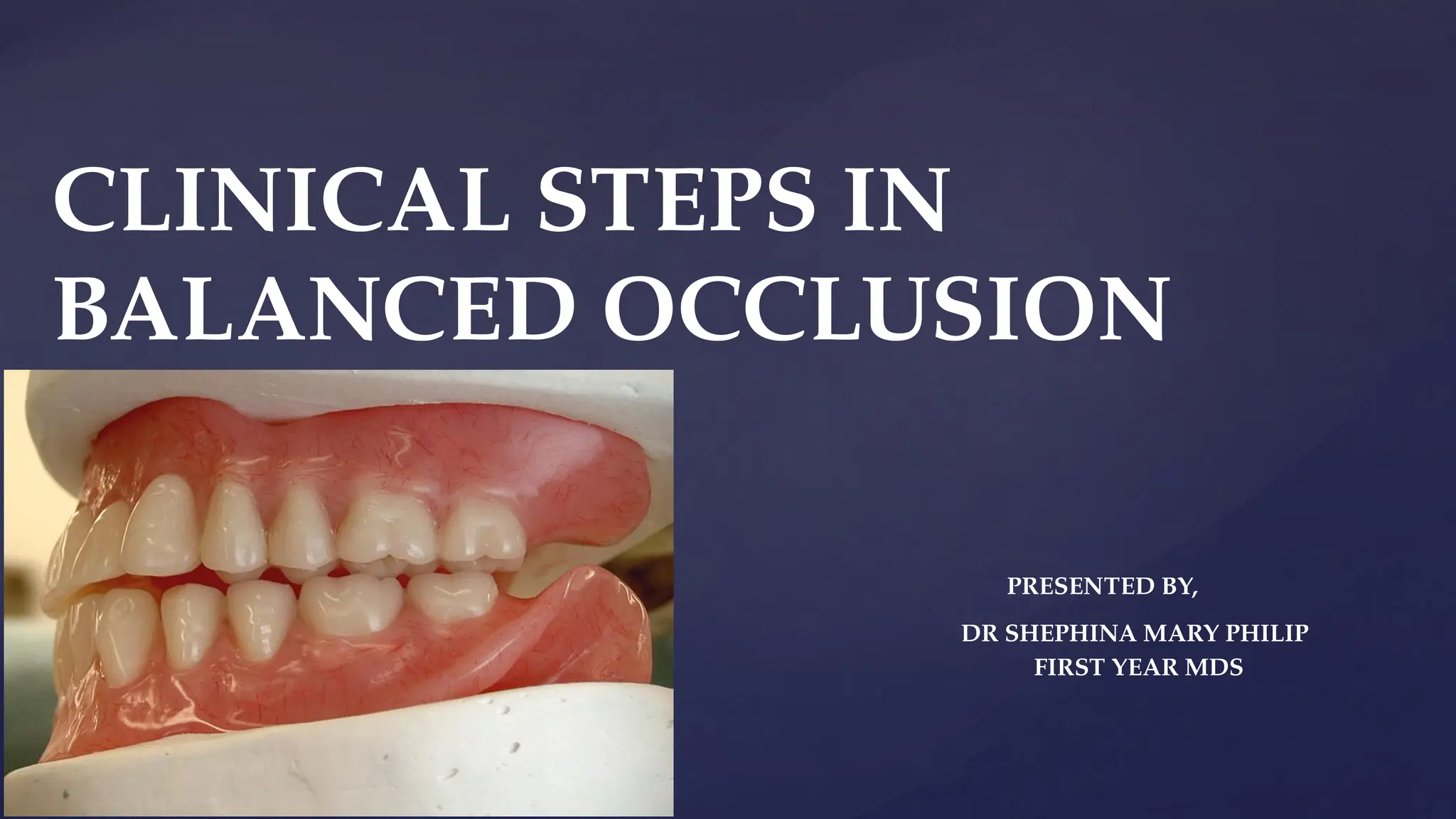
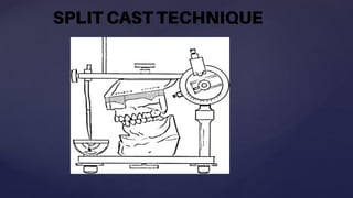
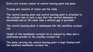
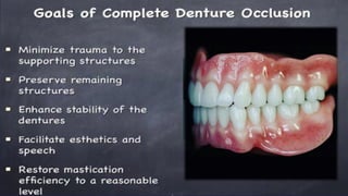
CLINICAL STEPS IN
BALANCED OCCLUSION
PRESENTED BY,
DR SHEPHINA MARY PHILIP
FIRST YEAR MDS
•Occlusion in complete denture must be developed to function
efficiently and with the least amount of trauma to the supporting
tissues.
•All dentures move in function and prime aim in construction of
complete dentures to ensure that this movement is reduced to the
minimum. When forces act on a body in such a way that no motion
results, there is BALANCE or equilibrium. Stable denture is the
ultimate goal
INTRODUCTION
 Definition : “ The simultaneous contacting of maxillary and mandibular
teeth on right and left and in the posterior and anterior occlusal areas
in centric and eccentric positions.”- Heartwell
 “Stable simultaneous contact of the opposing upper and lower teeth in
centric relation position and a continuous smooth bilateral gliding from
this position to any eccentric position within normal range of
mandibular function.”- Winkler
WHAT IS BALANCED OCCLUSION????
• To improve the stability of denture.
• To reduce resorption of the residual ridge and soreness.
• To improve oral comfort & well being of the patient
OBJECTIVES OF BALANCED OCCLUSION
• VERTICAL JAW RELATION
• ORIENTATION JAW RELATION USING FACE BOW
TRANSFER
• ZEROING OF SEMI ADJUSTABLE ARTICULATOR
• ARTICULATION OF MAXILLARY CAST USING SPLIT CAST
TECHNIQUE
• HORIZONTAL JAW RELATION USING NICK AND NOTCH
METHOD
CLINICAL PROCEDURE FOR ATTAINING BALANCED OCCLUSION
•
ARTICULATION OF MANDIBULAR CAST
• VERIFICATION OF HORIZONTAL JAW RELATION
USING GOTHIC ARCH TRACING
• INTEROCCLUSAL CHECK RECORDS
• PROGRAMMING OF SEMI ADJUSTABLE ARTICULATOR
• TEETH ARRANGMENT
• SELECTIVE GRINDING
VERTICAL JAW RELATION
Vertical jaw relation is defined as length of the face
as determined by the amount of separation of the
jaws- GPT
The maxillary and mandibular occlusal rims have been
prepared and patient adjusted to the correct vertical
dimension, the occlusal plane and the desired horizontal
overlap.
The occlusal surfaces of both rims shall be
appropriately notched to accept an interocclusal
recording material such as softened wax or quick
setting plaster.
ORIENTATION JAW RELATION USING
FACE BOW TRANSFER
The orientation relations are those that orient the mandible
to the cranium in such a way that when the mandible is kept
in its most posterior position, the mandible can rotate in its
sagittal plane around an imaginary transverse axis passing
through or near the condyles. The axis can be located when
the mandible is in its most posterior position by means of a
kinematic face bow or it can be approximated by use of an
arbitrary type of face bow.
Orientation jaw relation is defined as the jaw relation when
the mandible is kept in its most posterior position, it can
rotate in the sagittal plane around an imaginary transverse
axis passing through or near the condyles-- GPT
OPERATORY PROCEDURE.
1. The top of the Bitefork or Biteplane with the stem at the
patient’s left, is covered with a triple layer of baseplate
wax.
2. Heat seal the periphery and soften the wax throughout in a
water bath.
3. The softened wax impression material on the Bitefork is
seated against the occlusal surface of the upper rim and is
hand molded into and around the notches.
4.Preset the facebow on the face and tighten the condylar rods
on the arbitarary hinge axis which is 13mm anterior to the
most posterior point of tragus. Scale has to be adjusted
equally on both the sides.
5.Place the occlusal rim with the fork in the mouth and
position the face on the fork.
6.Connect the third reference point (orbitale or nasion)
7. Chill the Bitefork index and check to assure removal and
accurate replacement of the bite rim.
8.The Bitefork may alternately be attached directly to the
upper occlusal rim by heating the forks and piercing them
fully into the wax rim 3mm above the occlua plane also
9.The fork shall be parallel to the occlusal plane and shall
not distort the occlusal or notched surfaces. Long portion of
the fork should be parallel to the mid saggital plane and also
to the face bow.
ZEROING OF SEMI ADJUSTABLE
ARTICULATOR
A.Adjust the protrusive inclination of both Condylar Guidance to 33
degrees and tighten the thumbnuts
Note that the calibrations for these angles appear on both sides of
the Guidance housing and that the Right and Left can be seen and
adjusted from the same side of the Articulator.
B. Adjust the Bennett Angles of both Condylar Guidance at 33
degrees and tighten their thumbnuts.
C. Adjust the Incisal Pin to align the mid-line calibration to the top
edge of the Upper Member.
D. Adjust the Incisal Guide to a “zero” degree and tighten the
small Locknut.
E. Slide the Platform to align the Incisal Pin contact over the
“zero” indicating line on Guidance and tighten Platform
Lockscrew.
F. Articulators with Protrusive-Retrusive feature ONLY must be
adjusted to a “zero” centric.
G.Face bow is removed from the patient and transferred to the
articulator.
J. Orbital pointer pin should touch the underside of the orbital
plane indicator
K. Apply a thin coating of petroleum jelly to all surfaces of the
Articulator that will be exposed to the stone mounting media
L. Firmly attach a Mounting Plate to the Upper Member.
ARTICULATION OF MAXILLA TO THE SEMI
AJUSTABLE ARTICULATOR
USING SPLIT CAST TECHNIQUE
The first mention of ‘‘split casts’’ was by J.W. Needles in
1923.
The ‘‘split cast’’ is essentially a maxillary cast constructed in two parts
with a horizontal division.
The first part of the split maxillary master cast with index grooves,
is known as primary base. The design, number, and position of the index
grooves are determined on the basis of the
height of the palatal vault depth of the sulcus the personal
preference of the clinician. The second part, which is fitted
to the master cast and is attached to the upper member of
the articulator is referred to as secondary base or sandwich.
.
The perfect fit of the master cast, sandwich and upper
member of the articulator verifies the correct centric relation record.
If gap is present between the master cast and
Sandwich and upper member of the articulator,
that determines the previous recording of centric relation is
incorrect.
The sandwich should have a contrasting color for easy
Detection.
The splitcast mounting procedure allows for:
(i) Ease of removal and replacement of the casts.
(ii) To program the articulator by means of eccentric
records.
(iii) Verification of centric jaw relation records.
(iv) For correcting occlusal errors as a result of the
processing technique.
The literature shows use of following materials
for split cast mounting: plaster, sticky wax, masking tape
and elastic adhesive bandage
HORIZONTAL JAW RELATION
Horizontal jaw relation is the relationship
of the mandible to maxilla in a horizontal
plane. (anteroposterior and side to side
direction)
Pressureless method or NICK and NOTCH
METHOD
• Most commonly used method of indexing the recorded centric
jaw relation.
• Upto 3 mm of wax is removed on either side of the
mandibular occlusal rim from the premolar region till the distal
end. This depression created on the occlusal rim due to
removal of wax is called trough.
• On or more notches are cut on the corresponding area on
the maxillary occlusal rim. The notch prevents anteroposterior
movement
• One nick is cut anterior to the notch. It prevents the
lateral movement.
• The nick and notch on the maxillary occlusal rim are lubricated
with petrolatum
• The prepare occlusal rims are inserted into the patients mouth
and the patient is taught to close the mandible at the maximum
retruded position
• The mandible occlusal rim is removed from the patients mouth
• About 4.5mm of aluwax should be placed on the trough so that
about 1.5mm of aluwax will be projecting above the mandibular
occlusal rim.
• ZOE and impression plaster can also be used as a substitute for
Aluwax
VERIFICATION OF HORIZONTAL JAW
RELATION USING GOTHIC ARCH
TRACING
GOTHIC ARCH TRACING
Extra Oral Tracers
Dual components
Tracing plate, Stylus, central bearing
Point and plate
Less accurate
Larger arrow point
Easy to visualize
Intra Oral Tracers
Only Intra oral components
Central bearing device/tracing device
More accurate
Smaller arrow point
Difficult to visualize
SIMPLEX TRACER -Dentsply
DENTURE BALANCER -Leemark
HIGH EXTRA ORAL TRACER
Extra oral tracers consist of central bearing point and plate.
Tracing unit consists of stylus and the table
The central bearing plate and central bearing point is attached to
the occlusal rims in such a way that the vertical dimension is
maintained and at the same time a uniform gap is provided.
The central bearing plate is submerged into the maxillary occlusal
rim.
Height of the mandibular occlusal rim is reduced by 4mm and is
maintained parallel to the maxillay occlusal rim
The plate carrying the central bearing point is kept flushed with
the modified mandibular occlusal rim.
The central bearing point is in the form of a sphere because it
should maintain contact when the mandible protrudes, the
condyles translates and anterior portion of the occlusal rims get
approximated
Tracing table is attached to the buccal surfaces of the
mandibular rim
The tracing table is attached such that it does not interfere
with the incisal guide table.
Stylus unit is attached to the maxillary rim.
Gothic arch tracing made by the patient on a mixuture of zinc
oxide and spirit or on a soot base.
It can also be made on a wax medium
GOTHIC ARCH TRACING
CLASSICALPOINTED FORM
• Well defined apex
• Symmetrical
movements
• Healthy TMJ
• 120 Degree angle
CLASSICALFLA
T FORM
• Similar to classic form
• Marked movements
in fossa
• More obtuse angle
ASSYMETRICALGOTHIC
ARCH
• Asymmetry in
movements
• Inhibition of
forward movement
WEAKGOTHIC
ARCH OR
APEXABSENT/ROUND
FORM
• No sharp point
• Lateral
movements
• Practice
MINIATURE GOTHIC ARCH
• Similar to classic form
• Extension is limited
• Restricted movements
• Interference in
movements
• Improper seating of bases
• Long edentulousness
• Inhibition of movements
DOUBLEGOTHICARCH
• Two centric !!
• Two Vertical !!
• Training till single
is
achieved…………..
EXTENDED GOTHIC ARCH
• Protrusive path
beyond apex
• Forced strained
retrusive movements
• Active/passive
• Maxillary forwards
/mandibular
backward
displacment
INTERRUPTED
GOTHIC
ARCH
• Loss of continuity
• Interference by heels
of rims
 Not meeting at apex
 Long term denture wearer
 Wrong centric in previous
denture
ATYPICAL GOTHIC ARCH
Plastic template with hole is made at centric and 6mm protrusion to
hold the stylus at the desired point.
Now the occlusal rims are modified by closing the gaps between the
central bearing plates and the rim.
On the wax, triangular locating notches extending to the buccal surface
are prepared both on maxilla and mandible.
Petroleum jelly is smeared on the wax and the metal surface to act as
a separating medium
Interocclusal check record is obtained at centric.
Record is also obtained at 6mm protrusion
Page 18
Page 34
5
Page 3
Half-inclined appliance (about 14 degrees to the
occlusal plane) is recommended and reliable as
it
allows the
recording
points in a
convergent area
with
of tapping
the condyle in
optimum
position in the fossa.
g
6
Page 3
I
s
when the inclination of the central bearing plate is
greater than the axis path inclination, a
negative angle will be registered on a condylar
articulator.
ARTICLE:
Influence of the inclination of the plate of an intra-oral
tracing device on the condylar position registered by
tapping movement
MD. M. Rahman,S. Kohno,H. Kobayashi,K.
Sawada(2004)
Journal of Oral Rehabilitation,vol 31, no.6, pp.546-553
The object of this study was to determine the best inclination of the intra-oral
tracing device to get optimum condylar position with the registration of tapping
movement. Three appliances with different tracing plate inclinations were used
in five healthy subjects. The tracing plates were set at 0° to occlusal plane
(horizontal); at the angle formed by drawing a line from condylar point to the
stylus position at occlusal plane (inclined); then at the angle half to inclined
(half-inclined). Subjects made Gothic arch and tapping movements (n = 30)
at a 30 mm interincisal distance with the head Camper plane horizontal. The
incisal and condylar points were tracked with a 6-degree-of-freedom jaw
movement tracking system. The location of gothic arch apex, the distribution
and mean position of 30 tapping points from intercuspal position were analyzed
in incisal and condylar point between the appliances. Data were analyzed with
repeated measures one-way anova. Results showed that mean position of
tapping points were significantly different among the appliances. Half-inclined
appliance recorded tapping points in a convergent area nearer to intercuspal
position (IP) than other appliances. In all appliances, the contact points of the
tapping movement were anterior to Gothic arch apex.
Interoccusal
Records
Limited resistance before setting to avoid displacement of
mandible
Minimal dimensional changes after
setting Rigid or resilient after setting
Recording accuracy
Less setting time
Should be
verifiable
Interocclusal Record Materials
for Complete denture
• Type II Dental Plaster
• Rigid, Goodaccuracy, Flowable
in consistency after mixing
• Disadvantage: Setting Expansion
• Solution: Use of anti-
expansion solution
• Poly Vinyl Siloxane (PVS),
Polyether
• Rigid after setting, Light
body consistency, Accuracy,
Easy to trim without
distortion,
• Disadvantage: spring action
which may cause
inaccuracies during
mounting of the casts.
DENT
AL
PLASTER
ELASTOMER
S
Disadvan
tage:
• Setting
expansion
Solution:
Use of anti-expansion solution during mixing
Anti-expansion solution: 6% potassium sulphate and
0.6% borax
Rationale of making Interocclusal Records
CENTRIC RECORD:
• To verify centric jaw relation recorded tentatively with static
check bite method
ECCENTRICRECORDS(Protrusive & Lateral):
• Program Protrusive Condylar Guidance and Lateral Condylar
Guidance
PROGRAMMING THE
ARTICULATOR
• First the centric record has to be placed and it has to be
found out whether it matches with tentative centric relation.
• For this purpose, the bases with the tracing assembly is
brought back to the cast mounted in the articulator.
• After keeping the interocclusal record, the upper cast and
the lower cast are to be secured and for that the retentive pins
have to be incorporated on both the sides.
• With a thread, the lower cast, the lower base plaster
record, upper base and the upper cast should be secured into a
singular block.
Secure the Assembly using the Die Pin Tie
Thread Method
Secure the Assembly using the Die Pin Tie
Thread Method
• The upper member of the articulator with the upper split of the
cast should be approximated.
•At this point it is desirable to release the centric lock.
•When its approximated, both the parts of the split cast must
approximate closely.
• While it is closed, if the condylar spheres are making contact
with the respective stops it can be considered that the tentative
centric is matching with the graphic tracing.
•If the centric matches, the articulator can be programmed.
Verification of lower cast Remount
using Centric Record
The articulator has the capability to make translatory
movements for which the horizontal condylar path has to be
adjusted.
•For this purpose, protrusive record is used.
•Protrusive record is positioned and the casts are secured.
•Centric lock and the thumb screw will be released so that both
the condylar elements and the condylar path can be moved.
Upper member with the upper split is approximated
•If there is a gap, the brass disc containing the condylar path
can be moved so that the split gets completely obliterated.
•Note down the condylar path. The path is fixed at this point.
•The lateral condylar path in Hanua articulator will be adjusted
using the formula
 L =H/8 +12
• It will be approximately 15 degrees.
• From now onwards, the articulator will function as a
simulator of the patient’s jaw with movement capability both in
opening and in translation.
Program Protrusive
Condylar Guidance
THEHANAU QUINT IN BALANCED
ARTICULATION
CONDYLAR GUIDANCE
Mandibular guidance generated by condyle and articular disc traversing
contour of glenoid fossa
Condylar guidance is due to path followed by condyle in temporomandibular
joint
Obtained by protrusive registration record
CLINICAL SIGNIFICANCE:
Increase in condylar guidance will increase jaw separation during protrusion.
In patients with steep condylar guidance, incisal guidance should be
decreased to reduce amount of jaw separation produced during protrusion
As this factor cannot be modified, all other 4 factors should be modified to
compensate effects of this factor
INCISAL GUIDANCE
INCISAL GUIDE ANGLE: angle formed by intersection of plane of occlusion
and line with in sagittal plane determined by incisal edges of maxillary &
mandibular central incisors when teeth are in maximum intercuspation
(GPT-8)
Angle of incisal guidance is largely under influence of dentist
This factor is influenced by amount of horizontal, vertical overlap
Greater horizontal overlap = lesser angle of inclination
Greater the vertical overlap = greater angle of inclination
During protrusive movements mandibular teeth move downward & forward
as per incisal guidance.
For complete dentures the incisal guidance should be as flat as esthetics and
phonetics will permit.
If the incisal guidance is steep, steep cusps or occlusal plane or steep
compensatory curve is needed to balance occlusion
.
When the arrangement of the anterior teeth necessitates vertical overlap, a
compensating horizontal overlap should be set to prevent dominant incisal
guidance, from upsetting the occlusal balance on the posterior teeth
PLANE OF OCCLUSION
Defined as “An imaginary surface which is related anatomically to the cranium
and which theoretically touches the incisal edges of the incisors & the tips
of the occluding surfaces of posterior teeth.
It represents the mean curvature of the surface. Established anteriorly by
height of lower canine and posteriorly by height of retromolar pad.
(winkler). The plane of occlusion can be altered to a maximum of 10°
HANAU states plane of orientation is purely geometrical factor and pass
through central incisal point & summits of mesiobuccal cusps of molars.
Hanau used this plane for signifying general direction of masticatory surfaces
in denture space available & for characterization of compensating curve.
COMPENSATING CURVE
“The anterioposterior and lateral curvatures in the alignment of the occluding surfaces
and incisal edges of artificial teeth which are used to develop balanced occlusion”(GPT
-8)
Determined by inclination of posterior teeth and their vertical relationship to occlusal
plane.
The primary function thus of compensating curve is to provide balancing contacts for
protrusive mandibular movements. Without this curve it would be necessary to incline
the entire occlusal plane at an angle.
Steep condylar path requires steep compensating curve to produce balanced occlusion
Lesser compensating curve for the same condylar guidance will result in steeper incisal
guidance which will cause loss of molar balancing contact
ANTERIOPOSTERIOR: Curve of spee
MEDIOLATERAL: Monson’s curve Wilson’s curve
CUSPAL INCLINATION
Angle made by average slope of cusp with cusp plane measured mesiodistally
or bucco lingually
It is an important factor that modify the effect of plane of occlusion & the
compensating curves.
The angulation of the cusp is more important than the height of the cusps.
In shallow bite cases - cuspal angle should be reduced to balance the incisal
guidance.
Deep bite cases with steep incisal guidance , the jaw separation is more
during protrusion .Teeth with high cuspal inclines are required.
CONTACTS IN BALANCED OCCLUSION
Working side:
The mandibular buccal cusp ridges makes articular contact with the maxillary buccal cusp
ridges as the mandibular lingual cusp ridges are making contacts with the maxillary lingual
cusp ridges.
Balancing side:
The mandibular buccal cusps & their occlusal facing ridge, contacts maxillary lingual cusps
& ridge.
Protrusion:
Incisal edges of the mandibular anterior teeth contact with the lingual surface of the
maxillary anterior teeth. The mesiobuccal & lingual cusp ridges of the mandibular teeth
contact the distobuccal & lingual cusp ridges of the maxillary teeth.
SELECTIVE GRINDING
Selective gliding is defined as the, “intentional alteration of the occlusal surfaces of the
teeth to change their form’’ – GPT 8
How to do a selective grinding:
 Lock the articulator condyles to allow for hinge movement only.
 Use a blue articulating paper to mark teeth with high contacts in centric
relation.
 Loosen the condyles allow for eccentric movemnts.
 Use a red articulating paper to mark teeth with high contacts at eccentric
movements.
 High points are evaluated and centric prematurities are removed.
Centric position errors:
1) Pair of opposing teeth hold other teeth out of contact:
- deepen the fossae corresponding to cusps till other teeth came in contact.
2) Upper & lower teeth are nearly end to end:
-grind the inner inclines of upper buccal & lower lingual cusps.
-grind lingual of upper lingual cusps.
-grind buccal of lower buccal cusps.
3) Upper teeth are far buccal to lower ones:
- grind the inner inclines of upper lingual cusps & lower buccal cusps.
Working side errors:
1)both upper buccal & lower lingual cusps are long:
- grind the high cusp tips of non functional
2) buccal cusps make contact but lingual don’t:
- grind the buccal cusp tips & alter their inclines (in) non functional cusps).
3) lingual cusps make contact but buccal don’t:
- grind lingual cusps & alter their inclines (of non functional cusp only).
4) upper buccal & / or lingual cusps are mesial to intercuspation position:
- reduce upper mesial inclines & lower distal inclines
5) upper buccal & / or lingual cusps are distal to intercuspation position:
- reduce upper distal inclines & lower mesial inclines
6) teeth on working side are out of contact:
-selective grinding to balancing side
Balancing side errors
1) balancing side show heavy contact, and working side show no contact:
-grind the inner incline of lower buccal cusp.
2) no contact on balancing side:
-grind the buccal upper cusps or lower lingual cusps of cusps on working side.
Protrusive position errors:
1) anterior teeth show heavy contacts with no posterior contact:
- reduce palatal surface of upper anteriors & labial surface of lower anteriors.
2) posteriors show heavy contact with no anterior contact:
- grind distal inclines of upper cusps and mesial inclines of lower cusps.
CLINICAL STEPS IN BALANCED OCCLUSION.pptx

CLINICAL STEPS IN BALANCED OCCLUSION.pptx

  • 1.
    CLINICAL STEPS IN BALANCEDOCCLUSION PRESENTED BY, DR SHEPHINA MARY PHILIP FIRST YEAR MDS
  • 2.
    •Occlusion in completedenture must be developed to function efficiently and with the least amount of trauma to the supporting tissues. •All dentures move in function and prime aim in construction of complete dentures to ensure that this movement is reduced to the minimum. When forces act on a body in such a way that no motion results, there is BALANCE or equilibrium. Stable denture is the ultimate goal INTRODUCTION
  • 3.
     Definition :“ The simultaneous contacting of maxillary and mandibular teeth on right and left and in the posterior and anterior occlusal areas in centric and eccentric positions.”- Heartwell  “Stable simultaneous contact of the opposing upper and lower teeth in centric relation position and a continuous smooth bilateral gliding from this position to any eccentric position within normal range of mandibular function.”- Winkler WHAT IS BALANCED OCCLUSION????
  • 5.
    • To improvethe stability of denture. • To reduce resorption of the residual ridge and soreness. • To improve oral comfort & well being of the patient OBJECTIVES OF BALANCED OCCLUSION
  • 6.
    • VERTICAL JAWRELATION • ORIENTATION JAW RELATION USING FACE BOW TRANSFER • ZEROING OF SEMI ADJUSTABLE ARTICULATOR • ARTICULATION OF MAXILLARY CAST USING SPLIT CAST TECHNIQUE • HORIZONTAL JAW RELATION USING NICK AND NOTCH METHOD CLINICAL PROCEDURE FOR ATTAINING BALANCED OCCLUSION
  • 7.
    • ARTICULATION OF MANDIBULARCAST • VERIFICATION OF HORIZONTAL JAW RELATION USING GOTHIC ARCH TRACING • INTEROCCLUSAL CHECK RECORDS • PROGRAMMING OF SEMI ADJUSTABLE ARTICULATOR • TEETH ARRANGMENT • SELECTIVE GRINDING
  • 8.
  • 10.
    Vertical jaw relationis defined as length of the face as determined by the amount of separation of the jaws- GPT The maxillary and mandibular occlusal rims have been prepared and patient adjusted to the correct vertical dimension, the occlusal plane and the desired horizontal overlap. The occlusal surfaces of both rims shall be appropriately notched to accept an interocclusal recording material such as softened wax or quick setting plaster.
  • 11.
    ORIENTATION JAW RELATIONUSING FACE BOW TRANSFER
  • 12.
    The orientation relationsare those that orient the mandible to the cranium in such a way that when the mandible is kept in its most posterior position, the mandible can rotate in its sagittal plane around an imaginary transverse axis passing through or near the condyles. The axis can be located when the mandible is in its most posterior position by means of a kinematic face bow or it can be approximated by use of an arbitrary type of face bow. Orientation jaw relation is defined as the jaw relation when the mandible is kept in its most posterior position, it can rotate in the sagittal plane around an imaginary transverse axis passing through or near the condyles-- GPT
  • 13.
    OPERATORY PROCEDURE. 1. Thetop of the Bitefork or Biteplane with the stem at the patient’s left, is covered with a triple layer of baseplate wax. 2. Heat seal the periphery and soften the wax throughout in a water bath. 3. The softened wax impression material on the Bitefork is seated against the occlusal surface of the upper rim and is hand molded into and around the notches. 4.Preset the facebow on the face and tighten the condylar rods on the arbitarary hinge axis which is 13mm anterior to the most posterior point of tragus. Scale has to be adjusted equally on both the sides.
  • 14.
    5.Place the occlusalrim with the fork in the mouth and position the face on the fork. 6.Connect the third reference point (orbitale or nasion) 7. Chill the Bitefork index and check to assure removal and accurate replacement of the bite rim. 8.The Bitefork may alternately be attached directly to the upper occlusal rim by heating the forks and piercing them fully into the wax rim 3mm above the occlua plane also 9.The fork shall be parallel to the occlusal plane and shall not distort the occlusal or notched surfaces. Long portion of the fork should be parallel to the mid saggital plane and also to the face bow.
  • 15.
    ZEROING OF SEMIADJUSTABLE ARTICULATOR
  • 16.
    A.Adjust the protrusiveinclination of both Condylar Guidance to 33 degrees and tighten the thumbnuts Note that the calibrations for these angles appear on both sides of the Guidance housing and that the Right and Left can be seen and adjusted from the same side of the Articulator. B. Adjust the Bennett Angles of both Condylar Guidance at 33 degrees and tighten their thumbnuts. C. Adjust the Incisal Pin to align the mid-line calibration to the top edge of the Upper Member.
  • 17.
    D. Adjust theIncisal Guide to a “zero” degree and tighten the small Locknut. E. Slide the Platform to align the Incisal Pin contact over the “zero” indicating line on Guidance and tighten Platform Lockscrew. F. Articulators with Protrusive-Retrusive feature ONLY must be adjusted to a “zero” centric. G.Face bow is removed from the patient and transferred to the articulator.
  • 18.
    J. Orbital pointerpin should touch the underside of the orbital plane indicator K. Apply a thin coating of petroleum jelly to all surfaces of the Articulator that will be exposed to the stone mounting media L. Firmly attach a Mounting Plate to the Upper Member.
  • 19.
    ARTICULATION OF MAXILLATO THE SEMI AJUSTABLE ARTICULATOR USING SPLIT CAST TECHNIQUE
  • 21.
    The first mentionof ‘‘split casts’’ was by J.W. Needles in 1923. The ‘‘split cast’’ is essentially a maxillary cast constructed in two parts with a horizontal division. The first part of the split maxillary master cast with index grooves, is known as primary base. The design, number, and position of the index grooves are determined on the basis of the height of the palatal vault depth of the sulcus the personal preference of the clinician. The second part, which is fitted to the master cast and is attached to the upper member of the articulator is referred to as secondary base or sandwich. .
  • 22.
    The perfect fitof the master cast, sandwich and upper member of the articulator verifies the correct centric relation record. If gap is present between the master cast and Sandwich and upper member of the articulator, that determines the previous recording of centric relation is incorrect. The sandwich should have a contrasting color for easy Detection.
  • 24.
    The splitcast mountingprocedure allows for: (i) Ease of removal and replacement of the casts. (ii) To program the articulator by means of eccentric records. (iii) Verification of centric jaw relation records. (iv) For correcting occlusal errors as a result of the processing technique. The literature shows use of following materials for split cast mounting: plaster, sticky wax, masking tape and elastic adhesive bandage
  • 27.
  • 28.
    Horizontal jaw relationis the relationship of the mandible to maxilla in a horizontal plane. (anteroposterior and side to side direction)
  • 33.
    Pressureless method orNICK and NOTCH METHOD • Most commonly used method of indexing the recorded centric jaw relation. • Upto 3 mm of wax is removed on either side of the mandibular occlusal rim from the premolar region till the distal end. This depression created on the occlusal rim due to removal of wax is called trough. • On or more notches are cut on the corresponding area on the maxillary occlusal rim. The notch prevents anteroposterior movement • One nick is cut anterior to the notch. It prevents the lateral movement.
  • 34.
    • The nickand notch on the maxillary occlusal rim are lubricated with petrolatum • The prepare occlusal rims are inserted into the patients mouth and the patient is taught to close the mandible at the maximum retruded position • The mandible occlusal rim is removed from the patients mouth • About 4.5mm of aluwax should be placed on the trough so that about 1.5mm of aluwax will be projecting above the mandibular occlusal rim. • ZOE and impression plaster can also be used as a substitute for Aluwax
  • 36.
    VERIFICATION OF HORIZONTALJAW RELATION USING GOTHIC ARCH TRACING
  • 37.
  • 38.
    Extra Oral Tracers Dualcomponents Tracing plate, Stylus, central bearing Point and plate Less accurate Larger arrow point Easy to visualize Intra Oral Tracers Only Intra oral components Central bearing device/tracing device More accurate Smaller arrow point Difficult to visualize
  • 40.
  • 41.
  • 43.
    Extra oral tracersconsist of central bearing point and plate. Tracing unit consists of stylus and the table The central bearing plate and central bearing point is attached to the occlusal rims in such a way that the vertical dimension is maintained and at the same time a uniform gap is provided. The central bearing plate is submerged into the maxillary occlusal rim. Height of the mandibular occlusal rim is reduced by 4mm and is maintained parallel to the maxillay occlusal rim The plate carrying the central bearing point is kept flushed with the modified mandibular occlusal rim.
  • 44.
    The central bearingpoint is in the form of a sphere because it should maintain contact when the mandible protrudes, the condyles translates and anterior portion of the occlusal rims get approximated Tracing table is attached to the buccal surfaces of the mandibular rim The tracing table is attached such that it does not interfere with the incisal guide table. Stylus unit is attached to the maxillary rim. Gothic arch tracing made by the patient on a mixuture of zinc oxide and spirit or on a soot base. It can also be made on a wax medium
  • 45.
  • 48.
    CLASSICALPOINTED FORM • Welldefined apex • Symmetrical movements • Healthy TMJ • 120 Degree angle
  • 49.
    CLASSICALFLA T FORM • Similarto classic form • Marked movements in fossa • More obtuse angle
  • 50.
  • 51.
    WEAKGOTHIC ARCH OR APEXABSENT/ROUND FORM • Nosharp point • Lateral movements • Practice
  • 52.
    MINIATURE GOTHIC ARCH •Similar to classic form • Extension is limited • Restricted movements • Interference in movements • Improper seating of bases • Long edentulousness • Inhibition of movements
  • 53.
    DOUBLEGOTHICARCH • Two centric!! • Two Vertical !! • Training till single is achieved…………..
  • 54.
    EXTENDED GOTHIC ARCH •Protrusive path beyond apex • Forced strained retrusive movements • Active/passive • Maxillary forwards /mandibular backward displacment
  • 55.
    INTERRUPTED GOTHIC ARCH • Loss ofcontinuity • Interference by heels of rims
  • 56.
     Not meetingat apex  Long term denture wearer  Wrong centric in previous denture ATYPICAL GOTHIC ARCH
  • 57.
    Plastic template withhole is made at centric and 6mm protrusion to hold the stylus at the desired point. Now the occlusal rims are modified by closing the gaps between the central bearing plates and the rim. On the wax, triangular locating notches extending to the buccal surface are prepared both on maxilla and mandible. Petroleum jelly is smeared on the wax and the metal surface to act as a separating medium Interocclusal check record is obtained at centric. Record is also obtained at 6mm protrusion
  • 58.
  • 60.
  • 61.
    5 Page 3 Half-inclined appliance(about 14 degrees to the occlusal plane) is recommended and reliable as it allows the recording points in a convergent area with of tapping the condyle in optimum position in the fossa.
  • 62.
    g 6 Page 3 I s when theinclination of the central bearing plate is greater than the axis path inclination, a negative angle will be registered on a condylar articulator.
  • 63.
    ARTICLE: Influence of theinclination of the plate of an intra-oral tracing device on the condylar position registered by tapping movement MD. M. Rahman,S. Kohno,H. Kobayashi,K. Sawada(2004) Journal of Oral Rehabilitation,vol 31, no.6, pp.546-553
  • 64.
    The object ofthis study was to determine the best inclination of the intra-oral tracing device to get optimum condylar position with the registration of tapping movement. Three appliances with different tracing plate inclinations were used in five healthy subjects. The tracing plates were set at 0° to occlusal plane (horizontal); at the angle formed by drawing a line from condylar point to the stylus position at occlusal plane (inclined); then at the angle half to inclined (half-inclined). Subjects made Gothic arch and tapping movements (n = 30) at a 30 mm interincisal distance with the head Camper plane horizontal. The incisal and condylar points were tracked with a 6-degree-of-freedom jaw movement tracking system. The location of gothic arch apex, the distribution and mean position of 30 tapping points from intercuspal position were analyzed in incisal and condylar point between the appliances. Data were analyzed with repeated measures one-way anova. Results showed that mean position of tapping points were significantly different among the appliances. Half-inclined appliance recorded tapping points in a convergent area nearer to intercuspal position (IP) than other appliances. In all appliances, the contact points of the tapping movement were anterior to Gothic arch apex.
  • 65.
  • 67.
    Limited resistance beforesetting to avoid displacement of mandible Minimal dimensional changes after setting Rigid or resilient after setting Recording accuracy Less setting time Should be verifiable
  • 68.
    Interocclusal Record Materials forComplete denture • Type II Dental Plaster • Rigid, Goodaccuracy, Flowable in consistency after mixing • Disadvantage: Setting Expansion • Solution: Use of anti- expansion solution • Poly Vinyl Siloxane (PVS), Polyether • Rigid after setting, Light body consistency, Accuracy, Easy to trim without distortion, • Disadvantage: spring action which may cause inaccuracies during mounting of the casts. DENT AL PLASTER ELASTOMER S
  • 69.
    Disadvan tage: • Setting expansion Solution: Use ofanti-expansion solution during mixing Anti-expansion solution: 6% potassium sulphate and 0.6% borax
  • 72.
    Rationale of makingInterocclusal Records CENTRIC RECORD: • To verify centric jaw relation recorded tentatively with static check bite method ECCENTRICRECORDS(Protrusive & Lateral): • Program Protrusive Condylar Guidance and Lateral Condylar Guidance
  • 77.
  • 78.
    • First thecentric record has to be placed and it has to be found out whether it matches with tentative centric relation. • For this purpose, the bases with the tracing assembly is brought back to the cast mounted in the articulator. • After keeping the interocclusal record, the upper cast and the lower cast are to be secured and for that the retentive pins have to be incorporated on both the sides. • With a thread, the lower cast, the lower base plaster record, upper base and the upper cast should be secured into a singular block.
  • 79.
    Secure the Assemblyusing the Die Pin Tie Thread Method
  • 80.
    Secure the Assemblyusing the Die Pin Tie Thread Method
  • 81.
    • The uppermember of the articulator with the upper split of the cast should be approximated. •At this point it is desirable to release the centric lock. •When its approximated, both the parts of the split cast must approximate closely. • While it is closed, if the condylar spheres are making contact with the respective stops it can be considered that the tentative centric is matching with the graphic tracing. •If the centric matches, the articulator can be programmed.
  • 83.
    Verification of lowercast Remount using Centric Record
  • 84.
    The articulator hasthe capability to make translatory movements for which the horizontal condylar path has to be adjusted. •For this purpose, protrusive record is used. •Protrusive record is positioned and the casts are secured. •Centric lock and the thumb screw will be released so that both the condylar elements and the condylar path can be moved.
  • 85.
    Upper member withthe upper split is approximated •If there is a gap, the brass disc containing the condylar path can be moved so that the split gets completely obliterated. •Note down the condylar path. The path is fixed at this point. •The lateral condylar path in Hanua articulator will be adjusted using the formula  L =H/8 +12 • It will be approximately 15 degrees. • From now onwards, the articulator will function as a simulator of the patient’s jaw with movement capability both in opening and in translation.
  • 86.
  • 87.
    THEHANAU QUINT INBALANCED ARTICULATION
  • 88.
    CONDYLAR GUIDANCE Mandibular guidancegenerated by condyle and articular disc traversing contour of glenoid fossa Condylar guidance is due to path followed by condyle in temporomandibular joint Obtained by protrusive registration record CLINICAL SIGNIFICANCE: Increase in condylar guidance will increase jaw separation during protrusion. In patients with steep condylar guidance, incisal guidance should be decreased to reduce amount of jaw separation produced during protrusion As this factor cannot be modified, all other 4 factors should be modified to compensate effects of this factor
  • 89.
    INCISAL GUIDANCE INCISAL GUIDEANGLE: angle formed by intersection of plane of occlusion and line with in sagittal plane determined by incisal edges of maxillary & mandibular central incisors when teeth are in maximum intercuspation (GPT-8) Angle of incisal guidance is largely under influence of dentist This factor is influenced by amount of horizontal, vertical overlap Greater horizontal overlap = lesser angle of inclination Greater the vertical overlap = greater angle of inclination During protrusive movements mandibular teeth move downward & forward as per incisal guidance.
  • 90.
    For complete denturesthe incisal guidance should be as flat as esthetics and phonetics will permit. If the incisal guidance is steep, steep cusps or occlusal plane or steep compensatory curve is needed to balance occlusion . When the arrangement of the anterior teeth necessitates vertical overlap, a compensating horizontal overlap should be set to prevent dominant incisal guidance, from upsetting the occlusal balance on the posterior teeth
  • 92.
    PLANE OF OCCLUSION Definedas “An imaginary surface which is related anatomically to the cranium and which theoretically touches the incisal edges of the incisors & the tips of the occluding surfaces of posterior teeth. It represents the mean curvature of the surface. Established anteriorly by height of lower canine and posteriorly by height of retromolar pad. (winkler). The plane of occlusion can be altered to a maximum of 10° HANAU states plane of orientation is purely geometrical factor and pass through central incisal point & summits of mesiobuccal cusps of molars. Hanau used this plane for signifying general direction of masticatory surfaces in denture space available & for characterization of compensating curve.
  • 93.
    COMPENSATING CURVE “The anterioposteriorand lateral curvatures in the alignment of the occluding surfaces and incisal edges of artificial teeth which are used to develop balanced occlusion”(GPT -8) Determined by inclination of posterior teeth and their vertical relationship to occlusal plane. The primary function thus of compensating curve is to provide balancing contacts for protrusive mandibular movements. Without this curve it would be necessary to incline the entire occlusal plane at an angle. Steep condylar path requires steep compensating curve to produce balanced occlusion Lesser compensating curve for the same condylar guidance will result in steeper incisal guidance which will cause loss of molar balancing contact ANTERIOPOSTERIOR: Curve of spee MEDIOLATERAL: Monson’s curve Wilson’s curve
  • 94.
    CUSPAL INCLINATION Angle madeby average slope of cusp with cusp plane measured mesiodistally or bucco lingually It is an important factor that modify the effect of plane of occlusion & the compensating curves. The angulation of the cusp is more important than the height of the cusps. In shallow bite cases - cuspal angle should be reduced to balance the incisal guidance. Deep bite cases with steep incisal guidance , the jaw separation is more during protrusion .Teeth with high cuspal inclines are required.
  • 95.
    CONTACTS IN BALANCEDOCCLUSION Working side: The mandibular buccal cusp ridges makes articular contact with the maxillary buccal cusp ridges as the mandibular lingual cusp ridges are making contacts with the maxillary lingual cusp ridges. Balancing side: The mandibular buccal cusps & their occlusal facing ridge, contacts maxillary lingual cusps & ridge. Protrusion: Incisal edges of the mandibular anterior teeth contact with the lingual surface of the maxillary anterior teeth. The mesiobuccal & lingual cusp ridges of the mandibular teeth contact the distobuccal & lingual cusp ridges of the maxillary teeth.
  • 96.
    SELECTIVE GRINDING Selective glidingis defined as the, “intentional alteration of the occlusal surfaces of the teeth to change their form’’ – GPT 8 How to do a selective grinding:  Lock the articulator condyles to allow for hinge movement only.  Use a blue articulating paper to mark teeth with high contacts in centric relation.  Loosen the condyles allow for eccentric movemnts.  Use a red articulating paper to mark teeth with high contacts at eccentric movements.  High points are evaluated and centric prematurities are removed.
  • 100.
    Centric position errors: 1)Pair of opposing teeth hold other teeth out of contact: - deepen the fossae corresponding to cusps till other teeth came in contact. 2) Upper & lower teeth are nearly end to end: -grind the inner inclines of upper buccal & lower lingual cusps. -grind lingual of upper lingual cusps. -grind buccal of lower buccal cusps. 3) Upper teeth are far buccal to lower ones: - grind the inner inclines of upper lingual cusps & lower buccal cusps.
  • 103.
    Working side errors: 1)bothupper buccal & lower lingual cusps are long: - grind the high cusp tips of non functional 2) buccal cusps make contact but lingual don’t: - grind the buccal cusp tips & alter their inclines (in) non functional cusps). 3) lingual cusps make contact but buccal don’t: - grind lingual cusps & alter their inclines (of non functional cusp only). 4) upper buccal & / or lingual cusps are mesial to intercuspation position: - reduce upper mesial inclines & lower distal inclines 5) upper buccal & / or lingual cusps are distal to intercuspation position: - reduce upper distal inclines & lower mesial inclines 6) teeth on working side are out of contact: -selective grinding to balancing side
  • 108.
    Balancing side errors 1)balancing side show heavy contact, and working side show no contact: -grind the inner incline of lower buccal cusp. 2) no contact on balancing side: -grind the buccal upper cusps or lower lingual cusps of cusps on working side. Protrusive position errors: 1) anterior teeth show heavy contacts with no posterior contact: - reduce palatal surface of upper anteriors & labial surface of lower anteriors. 2) posteriors show heavy contact with no anterior contact: - grind distal inclines of upper cusps and mesial inclines of lower cusps.