
More Related Content
Viewers also liked
Viewers also liked (13)
Similar to CIRCLES OF COVERAGE FOR TELECOM ROOMS
Similar to CIRCLES OF COVERAGE FOR TELECOM ROOMS (20)
CIRCLES OF COVERAGE FOR TELECOM ROOMS
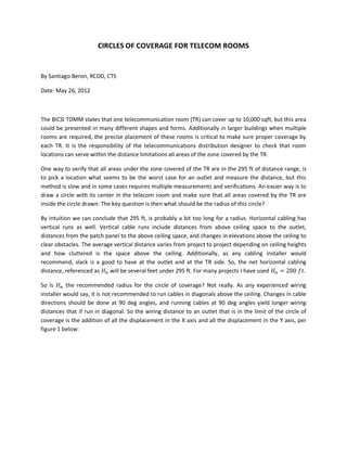
- 1. CIRCLES OF COVERAGE FOR TELECOM ROOMS By Santiago Beron, RCDD, CTS Date: May 26, 2012 The BICSI TDMM states that one telecommunication room (TR) can cover up to 10,000 sqft, but this area could be presented in many different shapes and forms. Additionally in larger buildings when multiple rooms are required, the precise placement of these rooms is critical to make sure proper coverage by each TR. It is the responsibility of the telecommunications distribution designer to check that room locations can serve within the distance limitations all areas of the zone covered by the TR. One way to verify that all areas under the zone covered of the TR are in the 295 ft of distance range, is to pick a location what seems to be the worst case for an outlet and measure the distance, but this method is slow and in some cases requires multiple measurements and verifications. An easier way is to draw a circle with its center in the telecom room and make sure that all areas covered by the TR are inside the circle drawn. The key question is then what should be the radius of this circle? By intuition we can conclude that 295 ft, is probably a bit too long for a radius. Horizontal cabling has vertical runs as well. Vertical cable runs include distances from above ceiling space to the outlet, distances from the patch panel to the above ceiling space, and changes in elevations above the ceiling to clear obstacles. The average vertical distance varies from project to project depending on ceiling heights and how cluttered is the space above the ceiling. Additionally, as any cabling installer would recommend, slack is a good to have at the outlet and at the TR side. So, the net horizontal cabling distance, referenced as will be several feet under 295 ft. For many projects I have used = 280 . So is the recommended radius for the circle of coverage? Not really. As any experienced wiring installer would say, it is not recommended to run cables in diagonals above the ceiling. Changes in cable directions should be done at 90 deg angles, and running cables at 90 deg angles yield longer wiring distances that if run in diagonal. So the wiring distance to an outlet that is in the limit of the circle of coverage is the addition of all the displacement in the X axis and all the displacement in the Y axis, per figure 1 below:
- 2. Figure 1 In a mathematical form, the distance to the outlet is then defined as: ( , ) = + It is also true that most likely you won’t run cables to an outlet as indicated in Figure 1, where first you run the wire along the X axis and then you run all your distance along the Y axis. In reality you will have multiple 90° deg changes in direction before you get to an outlet, but the addition of all the smaller movements along one axis add up to the same distance as a single move. Therefore, the formula defined above is still valid even if you have multiple changes in direction. From here forward estimating what the radius of the circle of coverage is a mathematical problem that has a solution. As proof to my teenage daughter that all the math that you are thought in school does have real life uses, the problem can be solved as follows: First, let’s make it a single variable problem by replacing Y, using the Pythagorean equation: = + √ − Where R is the radius of the circle an X can have a range of 0≤X≤R The next step is to find out for what value of X within the range, the distance is the greatest. If we find out this value, we can then go back and find out the value of Y, the value of the total wiring distance to the outlet and then make sure that it does not exceed the value of the net horizontal wiring distance . The equation for distance above is not straight forward, and in order to estimate the greatest value of the function it is required to find out where the function’s inflexion points are, and the value of the function at the two ends of the range (where X = 0 and X = R) . Inflection points are the points where the slope of the function equals 0, or the basically the points in the graph where the function changes from increasing values to decreasing values or vice-versa. It is therefore required to estimate the derivative of the function of distance as follows:
- 3. = 1 + √ − = 0 Solving for X in the equation above, = √2 So, the function of distance has an inflection point at the value above. This inflection point could be a maximum or a minimum, but by quick comparing of the value of the function at the ends of the range and at the inflexion point, it can be concluded that this inflection point is a maximum. Solving for Y using the Pythagorean equation again at the inflexion point, it turns out that = √2 Meaning, that exactly at the point where X = Y (or at a 45° angle) the wiring distance is the greatest. This was kind of intuitive, but without the mathematical proof, is just a hunch. Therefore, the function of the wiring distance at the worst case scenario (inflexion point) it is = √2 + √2 = 2 √2 The final step of the process is just to make sure that this worst case scenario does not exceed the maximum net horizontal cabling distance , and finding the value of the radius. = 2 √2 = Solving for R on the equation above, = √2 2 = 0.71 The conclusion is therefore that the radius of circle defining the area of coverage of a telecom room is equal to 71% of the maximum net horizontal cabling distance in the project. So, for the many cases when = 280 ., it can be concluded that R = 198.8 ft or rounding up, R = 200 ft. This is an easy to remember number. I acknowledge that in some projects when you are running cables to an outlet, you have to run the wires, for a short distance, in a direction opposite to the outlet location because of physical constrains in the building. In such cases the method of drawing circles of coverage will yield erroneous information, but nevertheless it can be used as a starting point for verifying basic coverage for a telecom room, and fine tune by reducing the radius further based on the designer’s criteria.