SlideShare a Scribd company logo
1 of 7
Download to read offline
Small catadioptric microscope optics
David R. Shafera
, Yung-Ho Chuangb
, J. Joseph Armstrongb
a
David Shafer Optical Design, 56 Drake Lane, Fairfield CT, USA 06430
b
KLA-Tencor, 160 Rio Robles, San Jose, CA, USA 95134
ABSTRACT
New catadioptric objectives have been developed with large bandwidths in the DUV, high numerical apertures (NAs),
and small size. This can be achieved using a single glass material. Designs are specifically optimized for loose alignment
tolerances and ease of manufacturability. Applications include broad band DUV imaging and high resolution immersion
imaging for industrial microscopy and life sciences.
Keywords: Catadioptric, DUV, broadband, microscope, objective
1. INTRODUCTION
There are many microscopy applications that can benefit from broad band DUV imaging. Some applications further
require immersion, cover glass correction, or operation over a wide temperature range. To be suitable for general use,
microscope objectives need to be small enough to fit into a standard microscope and have a reasonable cost. Currently
available microscope optics do not satisfy these requirements. We present a new catadioptric approach with the
capability to address these requirements. A 0.9 NA self corrected objective with a bandwidth from 266-800nm and field
size of 0.15 mm is possible using only seven fused silica elements. Variations on this design with up to eleven elements
have been optimized with many applications in mind including broad band DUV imaging and high resolution immersion
imaging for semiconductor inspection. NA’s of 1.2 are possible for broad band DUV or 193nm water immersion. The
designs are also ideally suited for biological applications in DUV fluorescence imaging and spectroscopy, UV resonance
Raman spectroscopy, multi-photon absorption imaging, and Optical Coherence Tomography. In addition, the design is
insensitive to variations in the glass index. This makes it suited for applications where optical performance must be
maintained over a very wide temperature range such as in aerospace are possible. The index tolerance for many of these
designs in fused silica is 500 ppm providing good broad band performance over an extreme temperature range. With
design modifications and lens material selections, broad band optics from the IR to DUV is possible. This also allows
broad band microscope objectives to be made with reduced cost using inexpensive materials and replication
technologies. In this report we present a prototype objective that is specifically optimized for loose alignment tolerances
and ease of manufacturability. Mechanical assemblies for DUV optics include nitrogen purging to prevent
contamination.
2. CURRENT OBJECTIVE APPROACHES
There are three different approaches to microscope objective design; dioptric (refractive), catoptric (reflective), and
catadioptric (reflective + refractive). Of the currently available objectives utilizing these approaches, there are a limited
number that are capable of good performance with high resolution below 400nm.
2.1 Dioptric
Dioptric or refractive microscope objectives are the standard for visible microscopy. The complexity and cost for this
style of objective increases depending of the amount of color correction. Refractive objectives for use in the DUV are
limited by the availability of optical materials. Unfortunately high NA refractive objectives can not be produced with
significant bandwidths that include wavelengths below 350nm because of the lack of glass types with high transmission
and the desired dispersion. Even if some glasses with low transmission are considered, they can not significantly
increase the bandwidth. Objectives have been designed using only fused silica and calcium fluoride material which have
high transmission below 350nm. However, due to the similarities in their dispersions, the bandwidths are limited by
chromatic aberration. Some single line objectives have been made using fused silica for 248nm and 266nm laser light
sources. However, these objectives have a very high cost making them impractical for many applications. In addition,
most high NA DUV refractive objectives have limited field sizes.
2.2 Catoptric
If an objective with a broad bandwidth is desired, a catoptric or all reflective solution seems to be an attractive option.
With this type of objective there is no issue with bandwidth or chromatic aberrations. Bandwidth is limited only by the
mirror coatings. However, designs that are axially symmetric, like the Schwarzschild two mirror design, have limited
NA, large central obscuration causing poor performance in the mid spatial frequencies, and limited field size even when
large diameter mirrors are used. There are many varieties of off axis mirror systems, however these have limited NA’s,
tend to be large, and offer challenging optical alignment.
2.3 Catadioptric
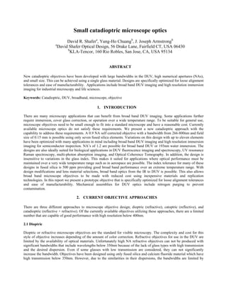
A typical form for a catadioptric objective is shown in Fig. 1. It has three primary lens groups: the catadioptric group, the
field lens group, and the focusing lens group. In this design the field lens group is located partially within the
catadioptric group.
Fig. 1 A typical catadioptric objective with three primary lens groups: Focusing group,
field lens group, and catadioptric group. In this design the field lens group is substantially
within the catadioptric group.
The catadioptric group is typically composed of two second surface mirrors or Mangin elements. Light from the object
enters the catadioptric group through an aperture in the mirror coating of the first Mangin element. The light then reflects
from the mirror coatings on second Mangin element and then the first Mangin element before passing through an
aperture or hole in the second Mangin element, forming an internal image near the field lens group. The location of each
Mangin element in relation to the object or internal image and its diameter determines the amount of obscuration. In
practice the obscuration can be limited to around 2% of the area so it has no significant impact on the performance. Light
from the internal field then passes though the field lens before entering the focusing lens group. The focusing lens group
is designed to correct for the residual aberrations of the catadioptric group and the field lens group. These objectives can
be self corrected and designed for an infinite conjugate. The currently available catadioptric objectives have diameters of
greater 80mm and lengths of greater than 60mm1, 2
. This is driven by the desire for large working distances, large
numerical apertures, and large field sizes. Optical manufacturing is also a factor in the size for catadioptric designs.
Highly accurate surfaces are required for the Mangin elements. Any surface figure error from the polishing of the
reflective surface is especially important because it is the equivalent of six refractive surfaces. Many high accuracy
optical polishing methods are not applicable to small sized, high curvature optics.
Focusing lens group
Catadioptric group
Field lens group
3. NEW SMALL CATADIOPTRIC APPROACH
Previous catadioptric objective designs were primarily targeted for semiconductor applications such as inspection and
lithography. An objective for general microscopy doesn’t require the large field size or long working distances common
to these applications. These requirements, along with improvements in the design form, allow for a small catadioptric
objective to be developed.
There are several standard parameters that will constrain the designs. Some of these include the focal length, total system
length, working distance, NA, field size, telecentricity in object space, and infinite conjugates. In addition, for an
objective to be practical for general microscopy volume manufacturability and reduced cost are also required. These
designs focus on reducing the alignment tolerances for the optical elements. This simplifies the typically time consuming
process of decenter adjustment and makes the design more robust to withstand mechanical shock. Additional design
goals help improve the final system performance. This includes low angles of incidence for good broad band coating
performance. All these requirements can be achieved with the new small catadioptric objective.
This style of catadioptric objective is based on the Schupmann medial telescope. The Schupmann telescope is a two lens
design that corrects for first order axial color using a single material. However, because the Schupmann telescope forms
a virtual image between the two lenses, a mirror arrangement is used instead to create a real image. Second order axial
color is then corrected with the addition of a field lens as suggested by Offner3
. This theory assumes an infinitely thin
field lens with zero dispersion with the field lens located at the internal paraxial image point.
In reality, the field lens has a finite thickness and dispersion which contributes its own aberration. One approach to
reduce the impact of the field lens dispersion is to achromatize the field lens by making it a doublet. This can effectively
correct for higher order chromatic aberrations. In the UV-DUV this can be accomplished using fused silica and calcium
fluoride materials for the field lens. However, this requires high curvature surfaces and the tolerances on the element
thickness, decenter, and index are quite tight. Another approach is look for a more general solution to achromatizing a
three lens system that also includes the thickness and dispersion of the field lens. A more general solution can be derived
and is used in these new designs. It is possible to use a finite thickness, single material field lens to correct for the axial
chromatic and first order lateral chromatic correction beyond what can be achieved by using the Schupmann and Offner
conditions. This improved correction is achieved by shifting the field lens away from the internal field. Figs 2a and 2b
show the transverse axial and lateral color aberrations for a shifted field lens compared to a field lens at the paraxial
focus.
Fig. 2a This plot shows the paraxial transverse axial color Fig. 2b This plot shows the paraxial transverse lateral color
for the Schupmann/Offner approach and the extended design for the Schupmann/Offner approach and the extended design
obtained from a general solution to the achromatic three lens obtained from a general solution to the achromatic three lens
problem. problem.
Transverse lateral color single material design
-0.3
-0.2
-0.1
0
0.1
0.2
0.3
260 320 380 440 500 560 620 680 740 800
Wavelength (nm)
Distancefromaxis(m)
Schupmann + Offner
Extended design
Diffraction limited radius
Transverse axial color for single material design
-0.3
-0.2
-0.1
0
0.1
0.2
0.3
260 320 380 440 500 560 620 680 740 800
Wavelength (nm)
Distancefromaxis(m)
Schupmann + Offner
Extended design
Diffraction limited radius
The Schupmann and Offner conditions provide 2nd
order correction and shifting the field lens increases the correction
capability to third order. Dotted lines are shown as a reference and indicate the increasing spot size with wavelength. The
distance between the dotted lines is equivalent to the diffraction limited spot diameter. The total transverse aberration is
equal to the sum of both the axial and lateral aberrations. The position of the field lens is chosen to minimize the total
aberration. For a larger fields, lateral color becomes the dominant aberration and more of the budget must be allocated to
lateral color correction.
The single material catadioptric design also has the advantage of being very insensitive to the absolute index of the glass.
This allows the design to maintain performance over a wide temperature range. This design has a refractive index
tolerance of 0.005. This is very large compared to the temperature sensitivity of the refractive index of fused silica at
approximately 0.00001 per deg C.
Many small catadioptric design forms with between 7 and 11 elements have been developed. The requirements for the
NA, field size, and bandwidth, and acceptable tolerances will drive the design complexity. One of the primary
constraints is the distance from the object to the last surface. This is set to be less than 45mm, the distance between the
object and the mounting flange on a standard microscope. An example design with 9 elements is shown in Fig. 3. The
diameter of the largest catadioptric element is 25mm. The polychromatic Strehl of this design is greater than 0.87 over
the field.
One of the important advantages of this design is the loose decenter tolerances. This makes the alignment of the
objective during manufacturing easier. A chart showing the decenter sensitivity of the objective is shown in Fig. 4. The
element with the largest decenter sensitivity is the Mangin element nearest the object. This sensitivity is driven by the
radius of curvature requirement for the surface nearest the object. The objective must fit on a standard microscope
objective turret. In practice many turrets accept a larger radius of curvature so this tolerance can be substantially
loosened.
If a somewhat larger obscuration is acceptable, the design can be simplified to seven elements while maintaining the
loose tolerances and good performance of the previous nine element design. An example of this design is shown in Fig.
5. The reduction in the required number of lenses comes from placing the second field lens on the opposite side of the
internal field compared to the 9 element design. This allows for better correction of the chromatic variation of
monochromatic aberrations, especially spherical and coma. The small catadioptric objective design is very flexible. This
design has extra degrees of freedom that can produce many solutions. These extra degrees of freedom are used to reduce
the manufacturing tolerances and limit the angles of incidence at each lens surface. This will produce the best objective
with the least cost.
Fig 3. An example 9 element design corrected from 266-
800nm. The diameter of the largest catadioptric element is
25mm. This design has an NA of 0.9 at the object with a
field size of 0.13mm. The obscuration is 0.8%.
Fig 4. This chart shows the wavefront error at
313nm from an element decenter of 10 microns with
no compensation. The objective exhibits a loose
decenter sensitivity.
Wavefront error from 10 micron decenter
0
0.05
0.1
0.15
0.2
0.25
0.3
0.35
9 8 7 6 5 4 3 2 1
Lens
RMSwavefronterrorat313nm
0 micron decenter
10 micron decenter
When using polychromatic Strehl as a metric with a
broad band system it is important to consider the
definition. The monochromatic Strehl is a ratio of the
intensity at the peak of the diffraction pattern of an
aberrated point image to that at the peak of an
aberration free image as formed by the same optical
system. The polychromatic Strehl is determined by the
incoherent addition of the peak intensities for each
wavelength being considered. One additional constraint
is the energy at each wavelength must be equal or
weighted appropriately. However the spot size is
smaller for the short wavelengths and the peak intensity
is proportional to the inverse square of the wavelength.
For example lets examine a system using wavelengths at
400nm and 800nm. The peak intensity at 400nm will be
4 times as high as the peak intensity at 800nm with
equal wavelength weighting. In this case the 400nm
wavelength will have 4 times the influence on the
polychromatic Strehl compared to the 800nm
wavelength. For this reason, the polychromatic Strehl may not be the best metric for many applications. An alternative
would be to specify the monochromatic aberrations, the axial color, and the lateral color separately. These metrics are
also more applicable for comparison to testing data gathered in the manufacturing process.
4. APPLICATIONS
Potential applications for this type of small catadioptric objective include semiconductor inspection and review, life
sciences, and other general microscopy applications. Objectives for semiconductor inspection have a variety of
challenging requirements including a large field size and very high Strehl ratio. The bandwidth these designs can support
is generally limited by higher order lateral color. These requirements generally add significant cost to the objectives.
Objective versions for semiconductor review don’t require a large field size, so their designs are more flexible and can
support larger bandwidths. Objective versions for biology have a wide variety of requirements that are driven by the
many detection and imaging techniques. The table in Fig. 6 summarizes some of these techniques and why they may be
suitable for the small catadioptric objective. Many standard techniques such as high resolution microscopy and
fluorescence detection may directly benefit by extending them into the DUV. Some of relatively new techniques
including UV resonance Raman spectroscopy, three photon imaging, and Optical Coherence Tomography may
substantially benefit from the broad band capabilities of the objective.
Many biological applications have additional requirements for cover glass correction and immersion imaging. Small
catadioptric objective designs have been investigates to address these requirements. The objective in Fig. 7 is an
objective corrected from 266-436nm over a 0.15mm field for a cover glass with a standard 0.17mm thickness. The major
challenge for broad band correction with a cover glass is allowing for variations in the cover glass thickness. By
adjusting air gaps it is possible to allow for thickness variations of ±10 microns. In principle this air gap adjustment can
be made with one mechanical motion of an adjusting ring on the objective housing. This design is also corrected over a
much larger field than the 10-20 micron field of a typical 0.9 NA objective. Designs with smaller field sizes would allow
for improved performance. The objective in Fig. 8 is an immersion objective corrected from 266-800nm over a 0.10mm
field with 1.2NA. Additional elements are added on one side of the internal field and between the Mangin element and
the object.
Fig 5. An example 7 element design corrected from 266-
800nm. The diameter of the largest catadioptric element is
25mm. This design has an NA of 0.9 at the object with a field
size of 0.13mm. The obscuration is 1.5% of the area.
DUV optics High NA
optics
Broad band
optics
Comment/Application advantage
High-resolution
microscopy
    DUV provides high resolution, but may kill living
samples
 Can generate UV/DUV artificial color maps.
 Can be used for sample review and classification.
Fluorescence imaging     Extend the fluorescence imaging to UV/DUV
 May not need dyes
UV absorption
spectroscopy
   Identify structural groups, for example carbonyl
group
 Extend the absorption spectroscopy to UV/DUV
Fluorescence time
domain analysis
  Analysis techniques include FIMDA, FCS, FxCS
Fluorescence
spectroscopy
   Extend to UV/DUV range
UV resonance Raman
spectroscopy
    Can analyze spectrally, temporally, and spatially
 In 220-270nm range, biology samples have little
fluorescence; good for analyzing phenylalanine,
tyrosine, tryptophan
Three photon
absorption
    Does not need DUV laser
Optical coherence
tomography
   Need UBB, not DUV
5. RESULTS
Prototype objectives using a similar design form to Fig. 3 are being developed. They are optimized for a field size of
0.13 mm and support a bandwidth of 266-800nm. Even though the design can support a broad range of wavelengths, the
wavelengths supported by the prototype objective are limited by the available optical coatings. The first prototype
objective has coatings with optimized transmission from 266-436nm. Later prototypes will test different coatings that
should extend the upper wavelength to 550nm.
Fig 7. An example 9 element design corrected from 266-
436nm over a 0.15mm field for use with a standard 0.17mm
cover glass.
Fig 8. An example 11 element design corrected
from 266-800nm with 1.2NA. Additional elements are
added on one side of the internal field and between the
Mangin element and the object.
Fig 6. This table summarizes some of the biological detection and imaging techniques that may be suitable for the small
catadioptric objective.
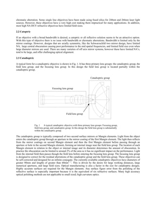
Fig 9. Picture of the first prototype objective using a
similar design to that presented in Fig. 3. The objective is
shown in the center position on a standard 6 position
microscope turret between two large diameter darkfield
objectives.
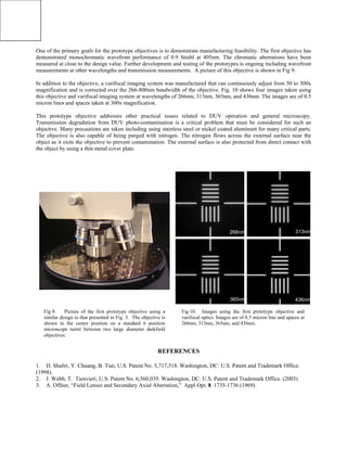
Fig 10. Images using the first prototype objective and
varifocal optics. Images are of 0.5 micron line and spaces at
266nm, 313nm, 365nm, and 436nm.
One of the primary goals for the prototype objectives is to demonstrate manufacturing feasibility. The first objective has
demonstrated monochromatic wavefront performance of 0.9 Strehl at 405nm. The chromatic aberrations have been
measured at close to the design value. Further development and testing of the prototypes is ongoing including wavefront
measurements at other wavelengths and transmission measurements. A picture of this objective is shown in Fig 9.
In addition to the objective, a varifocal imaging system was manufactured that can continuously adjust from 50 to 300x
magnification and is corrected over the 266-800nm bandwidth of the objective. Fig. 10 shows four images taken using
this objective and varifocal imaging system at wavelengths of 266nm, 313nm, 365nm, and 436nm. The images are of 0.5
micron lines and spaces taken at 300x magnification.
This prototype objective addresses other practical issues related to DUV operation and general microscopy.
Transmission degradation from DUV photo-contamination is a critical problem that must be considered for such an
objective. Many precautions are taken including using stainless steel or nickel coated aluminum for many critical parts.
The objective is also capable of being purged with nitrogen. The nitrogen flows across the external surface near the
object as it exits the objective to prevent contamination. The external surface is also protected from direct contact with
the object by using a thin metal cover plate.
REFERENCES
1. D. Shafer, Y. Chuang, B. Tsai, U.S. Patent No. 5,717,518. Washington, DC: U.S. Patent and Trademark Office.
(1998).
2. J. Webb, T. Tienvieri, U.S. Patent No. 6,560,039. Washington, DC: U.S. Patent and Trademark Office. (2003)
3. A. Offner, “Field Lenses and Secondary Axial Aberration,” Appl Opt. 8. 1735-1736 (1969).
266nm 313nm
365nm 436nm

More Related Content

What's hot

The evolution of a new high na broad spectrum catadioptric design
The evolution of a new high na broad spectrum catadioptric designThe evolution of a new high na broad spectrum catadioptric design
The evolution of a new high na broad spectrum catadioptric designDave Shafer
 
Multiple solutions in very simple optical designs
Multiple solutions in very simple optical designsMultiple solutions in very simple optical designs
Multiple solutions in very simple optical designsDave Shafer
 
Modified freeform offner, august 11, 2021
Modified freeform offner, august 11, 2021Modified freeform offner, august 11, 2021
Modified freeform offner, august 11, 2021Dave Shafer
 
Equivalent refracting surface and metasurfaces, april 2020
Equivalent refracting surface and metasurfaces, april 2020Equivalent refracting surface and metasurfaces, april 2020
Equivalent refracting surface and metasurfaces, april 2020Dave Shafer
 
A general lens design method, with a photographic lens example
A general lens design method, with a photographic lens exampleA general lens design method, with a photographic lens example
A general lens design method, with a photographic lens exampleDave Shafer
 
Five completely different methods of optical design
Five completely different methods of optical designFive completely different methods of optical design
Five completely different methods of optical designDave Shafer
 
The consequences of Petzval correction in lithographic system design
The consequences of Petzval correction in lithographic system designThe consequences of Petzval correction in lithographic system design
The consequences of Petzval correction in lithographic system designDave Shafer
 
Optimum design for a fast speed lens.
Optimum design for a fast speed lens.Optimum design for a fast speed lens.
Optimum design for a fast speed lens.Dave Shafer
 
Dennis gabor's catadioptric design and some new variations
Dennis gabor's catadioptric design and some new variationsDennis gabor's catadioptric design and some new variations
Dennis gabor's catadioptric design and some new variationsDave Shafer
 
Wide angle fast speed lens with only 4 elements
Wide angle fast speed lens with only 4 elementsWide angle fast speed lens with only 4 elements
Wide angle fast speed lens with only 4 elementsDave Shafer
 
Optical Design using stop shift theory
Optical Design using stop shift theoryOptical Design using stop shift theory
Optical Design using stop shift theoryDave Shafer
 
Extreme pixels per volume optical design
Extreme pixels per volume optical designExtreme pixels per volume optical design
Extreme pixels per volume optical designDave Shafer
 
Some unusual telescope designs
Some unusual telescope designsSome unusual telescope designs
Some unusual telescope designsDave Shafer
 
A remarkable new telescope objective design
A remarkable new telescope objective designA remarkable new telescope objective design
A remarkable new telescope objective designDave Shafer
 
More of a new family of freeform mirror telescopes
More of a new family of freeform mirror telescopesMore of a new family of freeform mirror telescopes
More of a new family of freeform mirror telescopesDave Shafer
 
Freeform aspheric talk
Freeform aspheric talkFreeform aspheric talk
Freeform aspheric talkDave Shafer
 
Innovation in optical design - a short history
Innovation in optical design -  a short historyInnovation in optical design -  a short history
Innovation in optical design - a short historyDave Shafer
 
Some odd and interesting monocentric designs 2005
Some odd and interesting monocentric designs   2005Some odd and interesting monocentric designs   2005
Some odd and interesting monocentric designs 2005Dave Shafer
 
Unusual mirror systems
Unusual mirror systemsUnusual mirror systems
Unusual mirror systemsDave Shafer
 
Lens designs with extreme image quality features
Lens designs with extreme image quality featuresLens designs with extreme image quality features
Lens designs with extreme image quality featuresDave Shafer
 

What's hot (20)

The evolution of a new high na broad spectrum catadioptric design
The evolution of a new high na broad spectrum catadioptric designThe evolution of a new high na broad spectrum catadioptric design
The evolution of a new high na broad spectrum catadioptric design
 
Multiple solutions in very simple optical designs
Multiple solutions in very simple optical designsMultiple solutions in very simple optical designs
Multiple solutions in very simple optical designs
 
Modified freeform offner, august 11, 2021
Modified freeform offner, august 11, 2021Modified freeform offner, august 11, 2021
Modified freeform offner, august 11, 2021
 
Equivalent refracting surface and metasurfaces, april 2020
Equivalent refracting surface and metasurfaces, april 2020Equivalent refracting surface and metasurfaces, april 2020
Equivalent refracting surface and metasurfaces, april 2020
 
A general lens design method, with a photographic lens example
A general lens design method, with a photographic lens exampleA general lens design method, with a photographic lens example
A general lens design method, with a photographic lens example
 
Five completely different methods of optical design
Five completely different methods of optical designFive completely different methods of optical design
Five completely different methods of optical design
 
The consequences of Petzval correction in lithographic system design
The consequences of Petzval correction in lithographic system designThe consequences of Petzval correction in lithographic system design
The consequences of Petzval correction in lithographic system design
 
Optimum design for a fast speed lens.
Optimum design for a fast speed lens.Optimum design for a fast speed lens.
Optimum design for a fast speed lens.
 
Dennis gabor's catadioptric design and some new variations
Dennis gabor's catadioptric design and some new variationsDennis gabor's catadioptric design and some new variations
Dennis gabor's catadioptric design and some new variations
 
Wide angle fast speed lens with only 4 elements
Wide angle fast speed lens with only 4 elementsWide angle fast speed lens with only 4 elements
Wide angle fast speed lens with only 4 elements
 
Optical Design using stop shift theory
Optical Design using stop shift theoryOptical Design using stop shift theory
Optical Design using stop shift theory
 
Extreme pixels per volume optical design
Extreme pixels per volume optical designExtreme pixels per volume optical design
Extreme pixels per volume optical design
 
Some unusual telescope designs
Some unusual telescope designsSome unusual telescope designs
Some unusual telescope designs
 
A remarkable new telescope objective design
A remarkable new telescope objective designA remarkable new telescope objective design
A remarkable new telescope objective design
 
More of a new family of freeform mirror telescopes
More of a new family of freeform mirror telescopesMore of a new family of freeform mirror telescopes
More of a new family of freeform mirror telescopes
 
Freeform aspheric talk
Freeform aspheric talkFreeform aspheric talk
Freeform aspheric talk
 
Innovation in optical design - a short history
Innovation in optical design -  a short historyInnovation in optical design -  a short history
Innovation in optical design - a short history
 
Some odd and interesting monocentric designs 2005
Some odd and interesting monocentric designs   2005Some odd and interesting monocentric designs   2005
Some odd and interesting monocentric designs 2005
 
Unusual mirror systems
Unusual mirror systemsUnusual mirror systems
Unusual mirror systems
 
Lens designs with extreme image quality features
Lens designs with extreme image quality featuresLens designs with extreme image quality features
Lens designs with extreme image quality features
 

Viewers also liked

A zoom lens design method, july 3, 2013
A zoom lens design method, july 3, 2013A zoom lens design method, july 3, 2013
A zoom lens design method, july 3, 2013Dave Shafer
 
Tight fit, cramming a lot of information through a small volume 1993
Tight fit,  cramming a lot of information through a small volume   1993Tight fit,  cramming a lot of information through a small volume   1993
Tight fit, cramming a lot of information through a small volume 1993Dave Shafer
 
Highlights of my 48 years in optical design
Highlights of my 48 years in optical designHighlights of my 48 years in optical design
Highlights of my 48 years in optical designDave Shafer
 
The John Henry lens design challenge
The John Henry lens design challengeThe John Henry lens design challenge
The John Henry lens design challengeDave Shafer
 
Highlights of my 51 years in optical design
Highlights of my 51 years in optical designHighlights of my 51 years in optical design
Highlights of my 51 years in optical designDave Shafer
 

Viewers also liked (6)

A zoom lens design method, july 3, 2013
A zoom lens design method, july 3, 2013A zoom lens design method, july 3, 2013
A zoom lens design method, july 3, 2013
 
Husserl talk
Husserl talkHusserl talk
Husserl talk
 
Tight fit, cramming a lot of information through a small volume 1993
Tight fit,  cramming a lot of information through a small volume   1993Tight fit,  cramming a lot of information through a small volume   1993
Tight fit, cramming a lot of information through a small volume 1993
 
Highlights of my 48 years in optical design
Highlights of my 48 years in optical designHighlights of my 48 years in optical design
Highlights of my 48 years in optical design
 
The John Henry lens design challenge
The John Henry lens design challengeThe John Henry lens design challenge
The John Henry lens design challenge
 
Highlights of my 51 years in optical design
Highlights of my 51 years in optical designHighlights of my 51 years in optical design
Highlights of my 51 years in optical design
 

Similar to Small catadioptric microscope optics 2003

SULI poster
SULI posterSULI poster
SULI posterTing Chi
 
Microscopy fin
Microscopy finMicroscopy fin
Microscopy finMUBOSScz
 
BN4406_group3_FinalProposal_05112014-3
BN4406_group3_FinalProposal_05112014-3BN4406_group3_FinalProposal_05112014-3
BN4406_group3_FinalProposal_05112014-3James Constantin
 
Closed Loop Control of Gimbal-less MEMS Mirrors for Increased Bandwidth in Li...
Closed Loop Control of Gimbal-less MEMS Mirrors for Increased Bandwidth in Li...Closed Loop Control of Gimbal-less MEMS Mirrors for Increased Bandwidth in Li...
Closed Loop Control of Gimbal-less MEMS Mirrors for Increased Bandwidth in Li...Ping Hsu
 
Lens enhancement considering for prescribing
Lens enhancement considering for prescribing Lens enhancement considering for prescribing
Lens enhancement considering for prescribing BRAHAMDEV MANDAL
 
laser lenses for retinal diseases
 laser lenses for retinal diseases laser lenses for retinal diseases
laser lenses for retinal diseasesnalini2218
 
lfcamera-150dpi-Copier.pdf
lfcamera-150dpi-Copier.pdflfcamera-150dpi-Copier.pdf
lfcamera-150dpi-Copier.pdfphotosavi
 
A biologically inspired cmos image sensor
A biologically inspired cmos image sensorA biologically inspired cmos image sensor
A biologically inspired cmos image sensorSpringer
 
A biologically inspired cmos image sensor
A biologically inspired cmos image sensorA biologically inspired cmos image sensor
A biologically inspired cmos image sensorSpringer
 
Catalog VORTEX All About Optics | Optics Trade | 2014
Catalog VORTEX All About Optics | Optics Trade | 2014Catalog VORTEX All About Optics | Optics Trade | 2014
Catalog VORTEX All About Optics | Optics Trade | 2014Optics-Trade
 
Micro Sample Measurement Using UV-Vis and Standard Optical Microscope
Micro Sample Measurement Using UV-Vis and Standard Optical MicroscopeMicro Sample Measurement Using UV-Vis and Standard Optical Microscope
Micro Sample Measurement Using UV-Vis and Standard Optical MicroscopeShimadzu Scientific Instruments
 
Shafer-Maksutov telescope
Shafer-Maksutov telescopeShafer-Maksutov telescope
Shafer-Maksutov telescopeDave Shafer
 
Gregorian telescope designs
Gregorian telescope designsGregorian telescope designs
Gregorian telescope designsDave Shafer
 
pAggieSpecREU2015
pAggieSpecREU2015pAggieSpecREU2015
pAggieSpecREU2015Shae Hart
 
Achieving high resolution digital photomicrographs
Achieving high resolution digital photomicrographsAchieving high resolution digital photomicrographs
Achieving high resolution digital photomicrographsLudwig Eckl
 
Khepricoat product-brochure
Khepricoat product-brochureKhepricoat product-brochure
Khepricoat product-brochureDavid Franz
 
Microstructure Intro Apr08
Microstructure Intro Apr08Microstructure Intro Apr08
Microstructure Intro Apr08Jim Nole
 

Similar to Small catadioptric microscope optics 2003 (20)

SULI poster
SULI posterSULI poster
SULI poster
 
Thin Film Analysis Using Shimadzu UV-2600
Thin Film Analysis Using Shimadzu UV-2600Thin Film Analysis Using Shimadzu UV-2600
Thin Film Analysis Using Shimadzu UV-2600
 
Microscopy fin
Microscopy finMicroscopy fin
Microscopy fin
 
BN4406_group3_FinalProposal_05112014-3
BN4406_group3_FinalProposal_05112014-3BN4406_group3_FinalProposal_05112014-3
BN4406_group3_FinalProposal_05112014-3
 
Closed Loop Control of Gimbal-less MEMS Mirrors for Increased Bandwidth in Li...
Closed Loop Control of Gimbal-less MEMS Mirrors for Increased Bandwidth in Li...Closed Loop Control of Gimbal-less MEMS Mirrors for Increased Bandwidth in Li...
Closed Loop Control of Gimbal-less MEMS Mirrors for Increased Bandwidth in Li...
 
Lens enhancement considering for prescribing
Lens enhancement considering for prescribing Lens enhancement considering for prescribing
Lens enhancement considering for prescribing
 
laser lenses for retinal diseases
 laser lenses for retinal diseases laser lenses for retinal diseases
laser lenses for retinal diseases
 
lfcamera-150dpi-Copier.pdf
lfcamera-150dpi-Copier.pdflfcamera-150dpi-Copier.pdf
lfcamera-150dpi-Copier.pdf
 
A biologically inspired cmos image sensor
A biologically inspired cmos image sensorA biologically inspired cmos image sensor
A biologically inspired cmos image sensor
 
A biologically inspired cmos image sensor
A biologically inspired cmos image sensorA biologically inspired cmos image sensor
A biologically inspired cmos image sensor
 
Catalog VORTEX All About Optics | Optics Trade | 2014
Catalog VORTEX All About Optics | Optics Trade | 2014Catalog VORTEX All About Optics | Optics Trade | 2014
Catalog VORTEX All About Optics | Optics Trade | 2014
 
Micro Sample Measurement Using UV-Vis and Standard Optical Microscope
Micro Sample Measurement Using UV-Vis and Standard Optical MicroscopeMicro Sample Measurement Using UV-Vis and Standard Optical Microscope
Micro Sample Measurement Using UV-Vis and Standard Optical Microscope
 
Shafer-Maksutov telescope
Shafer-Maksutov telescopeShafer-Maksutov telescope
Shafer-Maksutov telescope
 
Surgical operationg microscope
Surgical operationg microscopeSurgical operationg microscope
Surgical operationg microscope
 
Gregorian telescope designs
Gregorian telescope designsGregorian telescope designs
Gregorian telescope designs
 
pAggieSpecREU2015
pAggieSpecREU2015pAggieSpecREU2015
pAggieSpecREU2015
 
pAggieSpec
pAggieSpecpAggieSpec
pAggieSpec
 
Achieving high resolution digital photomicrographs
Achieving high resolution digital photomicrographsAchieving high resolution digital photomicrographs
Achieving high resolution digital photomicrographs
 
Khepricoat product-brochure
Khepricoat product-brochureKhepricoat product-brochure
Khepricoat product-brochure
 
Microstructure Intro Apr08
Microstructure Intro Apr08Microstructure Intro Apr08
Microstructure Intro Apr08
 

More from Dave Shafer

Aberration theory - A spectrum of design techniques for the perplexed - 1986.pdf
Aberration theory - A spectrum of design techniques for the perplexed - 1986.pdfAberration theory - A spectrum of design techniques for the perplexed - 1986.pdf
Aberration theory - A spectrum of design techniques for the perplexed - 1986.pdfDave Shafer
 
My interview.pptx
My interview.pptxMy interview.pptx
My interview.pptxDave Shafer
 
Snakes in the Bible, updated.pdf
Snakes in the Bible, updated.pdfSnakes in the Bible, updated.pdf
Snakes in the Bible, updated.pdfDave Shafer
 
How to optimize complex lens designs - 1993.pdf
How to optimize complex lens designs - 1993.pdfHow to optimize complex lens designs - 1993.pdf
How to optimize complex lens designs - 1993.pdfDave Shafer
 
interview with Dave Shafer.pdf
interview with Dave Shafer.pdfinterview with Dave Shafer.pdf
interview with Dave Shafer.pdfDave Shafer
 
Georgia senor center
Georgia senor centerGeorgia senor center
Georgia senor centerDave Shafer
 
Cooke triplet lens with freeform surfaces
Cooke triplet lens with freeform surfacesCooke triplet lens with freeform surfaces
Cooke triplet lens with freeform surfacesDave Shafer
 
Well corrected two element telescope with a flat image 1981
Well corrected two element telescope with a flat image   1981Well corrected two element telescope with a flat image   1981
Well corrected two element telescope with a flat image 1981Dave Shafer
 
Doing more with less 1995
Doing more with less   1995Doing more with less   1995
Doing more with less 1995Dave Shafer
 
Freeform Dyson design
Freeform Dyson designFreeform Dyson design
Freeform Dyson designDave Shafer
 
Apo triplet design
Apo triplet designApo triplet design
Apo triplet designDave Shafer
 
Schiefspiegler telescope with corrector lenses
Schiefspiegler telescope with corrector lensesSchiefspiegler telescope with corrector lenses
Schiefspiegler telescope with corrector lensesDave Shafer
 
Mirror corrector for a 10 meter fast speed parabola
Mirror corrector for a 10 meter fast speed parabolaMirror corrector for a 10 meter fast speed parabola
Mirror corrector for a 10 meter fast speed parabolaDave Shafer
 
A source of spiral fringes 1964
A source of spiral fringes  1964A source of spiral fringes  1964
A source of spiral fringes 1964Dave Shafer
 
New optical system corrected for all third order aberrations for all conjugat...
New optical system corrected for all third order aberrations for all conjugat...New optical system corrected for all third order aberrations for all conjugat...
New optical system corrected for all third order aberrations for all conjugat...Dave Shafer
 
The invention of the achromatic lens
The invention  of the achromatic lensThe invention  of the achromatic lens
The invention of the achromatic lensDave Shafer
 
Telephoto catadioptric design with broad spectral band correction
Telephoto catadioptric design with broad spectral  band correctionTelephoto catadioptric design with broad spectral  band correction
Telephoto catadioptric design with broad spectral band correctionDave Shafer
 
Social distancing
Social distancingSocial distancing
Social distancingDave Shafer
 
The biblical Exodus - what really happened?
The biblical Exodus - what really happened?The biblical Exodus - what really happened?
The biblical Exodus - what really happened?Dave Shafer
 

More from Dave Shafer (20)

Aberration theory - A spectrum of design techniques for the perplexed - 1986.pdf
Aberration theory - A spectrum of design techniques for the perplexed - 1986.pdfAberration theory - A spectrum of design techniques for the perplexed - 1986.pdf
Aberration theory - A spectrum of design techniques for the perplexed - 1986.pdf
 
My interview.pptx
My interview.pptxMy interview.pptx
My interview.pptx
 
Snakes in the Bible, updated.pdf
Snakes in the Bible, updated.pdfSnakes in the Bible, updated.pdf
Snakes in the Bible, updated.pdf
 
How to optimize complex lens designs - 1993.pdf
How to optimize complex lens designs - 1993.pdfHow to optimize complex lens designs - 1993.pdf
How to optimize complex lens designs - 1993.pdf
 
interview with Dave Shafer.pdf
interview with Dave Shafer.pdfinterview with Dave Shafer.pdf
interview with Dave Shafer.pdf
 
Georgia senor center
Georgia senor centerGeorgia senor center
Georgia senor center
 
Mireille email
Mireille emailMireille email
Mireille email
 
Cooke triplet lens with freeform surfaces
Cooke triplet lens with freeform surfacesCooke triplet lens with freeform surfaces
Cooke triplet lens with freeform surfaces
 
Well corrected two element telescope with a flat image 1981
Well corrected two element telescope with a flat image   1981Well corrected two element telescope with a flat image   1981
Well corrected two element telescope with a flat image 1981
 
Doing more with less 1995
Doing more with less   1995Doing more with less   1995
Doing more with less 1995
 
Freeform Dyson design
Freeform Dyson designFreeform Dyson design
Freeform Dyson design
 
Apo triplet design
Apo triplet designApo triplet design
Apo triplet design
 
Schiefspiegler telescope with corrector lenses
Schiefspiegler telescope with corrector lensesSchiefspiegler telescope with corrector lenses
Schiefspiegler telescope with corrector lenses
 
Mirror corrector for a 10 meter fast speed parabola
Mirror corrector for a 10 meter fast speed parabolaMirror corrector for a 10 meter fast speed parabola
Mirror corrector for a 10 meter fast speed parabola
 
A source of spiral fringes 1964
A source of spiral fringes  1964A source of spiral fringes  1964
A source of spiral fringes 1964
 
New optical system corrected for all third order aberrations for all conjugat...
New optical system corrected for all third order aberrations for all conjugat...New optical system corrected for all third order aberrations for all conjugat...
New optical system corrected for all third order aberrations for all conjugat...
 
The invention of the achromatic lens
The invention  of the achromatic lensThe invention  of the achromatic lens
The invention of the achromatic lens
 
Telephoto catadioptric design with broad spectral band correction
Telephoto catadioptric design with broad spectral  band correctionTelephoto catadioptric design with broad spectral  band correction
Telephoto catadioptric design with broad spectral band correction
 
Social distancing
Social distancingSocial distancing
Social distancing
 
The biblical Exodus - what really happened?
The biblical Exodus - what really happened?The biblical Exodus - what really happened?
The biblical Exodus - what really happened?
 

Recently uploaded

main PPT.pptx of girls hostel security using rfid
main PPT.pptx of girls hostel security using rfidmain PPT.pptx of girls hostel security using rfid
main PPT.pptx of girls hostel security using rfidNikhilNagaraju
 
Call Girls Delhi {Jodhpur} 9711199012 high profile service
Call Girls Delhi {Jodhpur} 9711199012 high profile serviceCall Girls Delhi {Jodhpur} 9711199012 high profile service
Call Girls Delhi {Jodhpur} 9711199012 high profile servicerehmti665
 
APPLICATIONS-AC/DC DRIVES-OPERATING CHARACTERISTICS
APPLICATIONS-AC/DC DRIVES-OPERATING CHARACTERISTICSAPPLICATIONS-AC/DC DRIVES-OPERATING CHARACTERISTICS
APPLICATIONS-AC/DC DRIVES-OPERATING CHARACTERISTICSKurinjimalarL3
 
MANUFACTURING PROCESS-II UNIT-5 NC MACHINE TOOLS
MANUFACTURING PROCESS-II UNIT-5 NC MACHINE TOOLSMANUFACTURING PROCESS-II UNIT-5 NC MACHINE TOOLS
MANUFACTURING PROCESS-II UNIT-5 NC MACHINE TOOLSSIVASHANKAR N
 
The Most Attractive Pune Call Girls Budhwar Peth 8250192130 Will You Miss Thi...
The Most Attractive Pune Call Girls Budhwar Peth 8250192130 Will You Miss Thi...The Most Attractive Pune Call Girls Budhwar Peth 8250192130 Will You Miss Thi...
The Most Attractive Pune Call Girls Budhwar Peth 8250192130 Will You Miss Thi...ranjana rawat
 
Architect Hassan Khalil Portfolio for 2024
Architect Hassan Khalil Portfolio for 2024Architect Hassan Khalil Portfolio for 2024
Architect Hassan Khalil Portfolio for 2024hassan khalil
 
High Profile Call Girls Nagpur Isha Call 7001035870 Meet With Nagpur Escorts
High Profile Call Girls Nagpur Isha Call 7001035870 Meet With Nagpur EscortsHigh Profile Call Girls Nagpur Isha Call 7001035870 Meet With Nagpur Escorts
High Profile Call Girls Nagpur Isha Call 7001035870 Meet With Nagpur Escortsranjana rawat
 
Gfe Mayur Vihar Call Girls Service WhatsApp -> 9999965857 Available 24x7 ^ De...
Gfe Mayur Vihar Call Girls Service WhatsApp -> 9999965857 Available 24x7 ^ De...Gfe Mayur Vihar Call Girls Service WhatsApp -> 9999965857 Available 24x7 ^ De...
Gfe Mayur Vihar Call Girls Service WhatsApp -> 9999965857 Available 24x7 ^ De...srsj9000
 
SPICE PARK APR2024 ( 6,793 SPICE Models )
SPICE PARK APR2024 ( 6,793 SPICE Models )SPICE PARK APR2024 ( 6,793 SPICE Models )
SPICE PARK APR2024 ( 6,793 SPICE Models )Tsuyoshi Horigome
 
Analog to Digital and Digital to Analog Converter
Analog to Digital and Digital to Analog ConverterAnalog to Digital and Digital to Analog Converter
Analog to Digital and Digital to Analog ConverterAbhinavSharma374939
 
Coefficient of Thermal Expansion and their Importance.pptx
Coefficient of Thermal Expansion and their Importance.pptxCoefficient of Thermal Expansion and their Importance.pptx
Coefficient of Thermal Expansion and their Importance.pptxAsutosh Ranjan
 
VIP Call Girls Service Kondapur Hyderabad Call +91-8250192130
VIP Call Girls Service Kondapur Hyderabad Call +91-8250192130VIP Call Girls Service Kondapur Hyderabad Call +91-8250192130
VIP Call Girls Service Kondapur Hyderabad Call +91-8250192130Suhani Kapoor
 
Sheet Pile Wall Design and Construction: A Practical Guide for Civil Engineer...
Sheet Pile Wall Design and Construction: A Practical Guide for Civil Engineer...Sheet Pile Wall Design and Construction: A Practical Guide for Civil Engineer...
Sheet Pile Wall Design and Construction: A Practical Guide for Civil Engineer...Dr.Costas Sachpazis
 
(SHREYA) Chakan Call Girls Just Call 7001035870 [ Cash on Delivery ] Pune Esc...
(SHREYA) Chakan Call Girls Just Call 7001035870 [ Cash on Delivery ] Pune Esc...(SHREYA) Chakan Call Girls Just Call 7001035870 [ Cash on Delivery ] Pune Esc...
(SHREYA) Chakan Call Girls Just Call 7001035870 [ Cash on Delivery ] Pune Esc...ranjana rawat
 
High Profile Call Girls Nagpur Meera Call 7001035870 Meet With Nagpur Escorts
High Profile Call Girls Nagpur Meera Call 7001035870 Meet With Nagpur EscortsHigh Profile Call Girls Nagpur Meera Call 7001035870 Meet With Nagpur Escorts
High Profile Call Girls Nagpur Meera Call 7001035870 Meet With Nagpur EscortsCall Girls in Nagpur High Profile
 
Model Call Girl in Narela Delhi reach out to us at 🔝8264348440🔝
Model Call Girl in Narela Delhi reach out to us at 🔝8264348440🔝Model Call Girl in Narela Delhi reach out to us at 🔝8264348440🔝
Model Call Girl in Narela Delhi reach out to us at 🔝8264348440🔝soniya singh
 
Introduction to IEEE STANDARDS and its different types.pptx
Introduction to IEEE STANDARDS and its different types.pptxIntroduction to IEEE STANDARDS and its different types.pptx
Introduction to IEEE STANDARDS and its different types.pptxupamatechverse
 
Software Development Life Cycle By Team Orange (Dept. of Pharmacy)
Software Development Life Cycle By  Team Orange (Dept. of Pharmacy)Software Development Life Cycle By  Team Orange (Dept. of Pharmacy)
Software Development Life Cycle By Team Orange (Dept. of Pharmacy)Suman Mia
 

Recently uploaded (20)

9953056974 Call Girls In South Ex, Escorts (Delhi) NCR.pdf
9953056974 Call Girls In South Ex, Escorts (Delhi) NCR.pdf9953056974 Call Girls In South Ex, Escorts (Delhi) NCR.pdf
9953056974 Call Girls In South Ex, Escorts (Delhi) NCR.pdf
 
main PPT.pptx of girls hostel security using rfid
main PPT.pptx of girls hostel security using rfidmain PPT.pptx of girls hostel security using rfid
main PPT.pptx of girls hostel security using rfid
 
Call Girls Delhi {Jodhpur} 9711199012 high profile service
Call Girls Delhi {Jodhpur} 9711199012 high profile serviceCall Girls Delhi {Jodhpur} 9711199012 high profile service
Call Girls Delhi {Jodhpur} 9711199012 high profile service
 
APPLICATIONS-AC/DC DRIVES-OPERATING CHARACTERISTICS
APPLICATIONS-AC/DC DRIVES-OPERATING CHARACTERISTICSAPPLICATIONS-AC/DC DRIVES-OPERATING CHARACTERISTICS
APPLICATIONS-AC/DC DRIVES-OPERATING CHARACTERISTICS
 
MANUFACTURING PROCESS-II UNIT-5 NC MACHINE TOOLS
MANUFACTURING PROCESS-II UNIT-5 NC MACHINE TOOLSMANUFACTURING PROCESS-II UNIT-5 NC MACHINE TOOLS
MANUFACTURING PROCESS-II UNIT-5 NC MACHINE TOOLS
 
The Most Attractive Pune Call Girls Budhwar Peth 8250192130 Will You Miss Thi...
The Most Attractive Pune Call Girls Budhwar Peth 8250192130 Will You Miss Thi...The Most Attractive Pune Call Girls Budhwar Peth 8250192130 Will You Miss Thi...
The Most Attractive Pune Call Girls Budhwar Peth 8250192130 Will You Miss Thi...
 
Architect Hassan Khalil Portfolio for 2024
Architect Hassan Khalil Portfolio for 2024Architect Hassan Khalil Portfolio for 2024
Architect Hassan Khalil Portfolio for 2024
 
High Profile Call Girls Nagpur Isha Call 7001035870 Meet With Nagpur Escorts
High Profile Call Girls Nagpur Isha Call 7001035870 Meet With Nagpur EscortsHigh Profile Call Girls Nagpur Isha Call 7001035870 Meet With Nagpur Escorts
High Profile Call Girls Nagpur Isha Call 7001035870 Meet With Nagpur Escorts
 
Gfe Mayur Vihar Call Girls Service WhatsApp -> 9999965857 Available 24x7 ^ De...
Gfe Mayur Vihar Call Girls Service WhatsApp -> 9999965857 Available 24x7 ^ De...Gfe Mayur Vihar Call Girls Service WhatsApp -> 9999965857 Available 24x7 ^ De...
Gfe Mayur Vihar Call Girls Service WhatsApp -> 9999965857 Available 24x7 ^ De...
 
SPICE PARK APR2024 ( 6,793 SPICE Models )
SPICE PARK APR2024 ( 6,793 SPICE Models )SPICE PARK APR2024 ( 6,793 SPICE Models )
SPICE PARK APR2024 ( 6,793 SPICE Models )
 
★ CALL US 9953330565 ( HOT Young Call Girls In Badarpur delhi NCR
★ CALL US 9953330565 ( HOT Young Call Girls In Badarpur delhi NCR★ CALL US 9953330565 ( HOT Young Call Girls In Badarpur delhi NCR
★ CALL US 9953330565 ( HOT Young Call Girls In Badarpur delhi NCR
 
Analog to Digital and Digital to Analog Converter
Analog to Digital and Digital to Analog ConverterAnalog to Digital and Digital to Analog Converter
Analog to Digital and Digital to Analog Converter
 
Coefficient of Thermal Expansion and their Importance.pptx
Coefficient of Thermal Expansion and their Importance.pptxCoefficient of Thermal Expansion and their Importance.pptx
Coefficient of Thermal Expansion and their Importance.pptx
 
VIP Call Girls Service Kondapur Hyderabad Call +91-8250192130
VIP Call Girls Service Kondapur Hyderabad Call +91-8250192130VIP Call Girls Service Kondapur Hyderabad Call +91-8250192130
VIP Call Girls Service Kondapur Hyderabad Call +91-8250192130
 
Sheet Pile Wall Design and Construction: A Practical Guide for Civil Engineer...
Sheet Pile Wall Design and Construction: A Practical Guide for Civil Engineer...Sheet Pile Wall Design and Construction: A Practical Guide for Civil Engineer...
Sheet Pile Wall Design and Construction: A Practical Guide for Civil Engineer...
 
(SHREYA) Chakan Call Girls Just Call 7001035870 [ Cash on Delivery ] Pune Esc...
(SHREYA) Chakan Call Girls Just Call 7001035870 [ Cash on Delivery ] Pune Esc...(SHREYA) Chakan Call Girls Just Call 7001035870 [ Cash on Delivery ] Pune Esc...
(SHREYA) Chakan Call Girls Just Call 7001035870 [ Cash on Delivery ] Pune Esc...
 
High Profile Call Girls Nagpur Meera Call 7001035870 Meet With Nagpur Escorts
High Profile Call Girls Nagpur Meera Call 7001035870 Meet With Nagpur EscortsHigh Profile Call Girls Nagpur Meera Call 7001035870 Meet With Nagpur Escorts
High Profile Call Girls Nagpur Meera Call 7001035870 Meet With Nagpur Escorts
 
Model Call Girl in Narela Delhi reach out to us at 🔝8264348440🔝
Model Call Girl in Narela Delhi reach out to us at 🔝8264348440🔝Model Call Girl in Narela Delhi reach out to us at 🔝8264348440🔝
Model Call Girl in Narela Delhi reach out to us at 🔝8264348440🔝
 
Introduction to IEEE STANDARDS and its different types.pptx
Introduction to IEEE STANDARDS and its different types.pptxIntroduction to IEEE STANDARDS and its different types.pptx
Introduction to IEEE STANDARDS and its different types.pptx
 
Software Development Life Cycle By Team Orange (Dept. of Pharmacy)
Software Development Life Cycle By  Team Orange (Dept. of Pharmacy)Software Development Life Cycle By  Team Orange (Dept. of Pharmacy)
Software Development Life Cycle By Team Orange (Dept. of Pharmacy)
 

Small catadioptric microscope optics 2003

  • 1. Small catadioptric microscope optics David R. Shafera , Yung-Ho Chuangb , J. Joseph Armstrongb a David Shafer Optical Design, 56 Drake Lane, Fairfield CT, USA 06430 b KLA-Tencor, 160 Rio Robles, San Jose, CA, USA 95134 ABSTRACT New catadioptric objectives have been developed with large bandwidths in the DUV, high numerical apertures (NAs), and small size. This can be achieved using a single glass material. Designs are specifically optimized for loose alignment tolerances and ease of manufacturability. Applications include broad band DUV imaging and high resolution immersion imaging for industrial microscopy and life sciences. Keywords: Catadioptric, DUV, broadband, microscope, objective 1. INTRODUCTION There are many microscopy applications that can benefit from broad band DUV imaging. Some applications further require immersion, cover glass correction, or operation over a wide temperature range. To be suitable for general use, microscope objectives need to be small enough to fit into a standard microscope and have a reasonable cost. Currently available microscope optics do not satisfy these requirements. We present a new catadioptric approach with the capability to address these requirements. A 0.9 NA self corrected objective with a bandwidth from 266-800nm and field size of 0.15 mm is possible using only seven fused silica elements. Variations on this design with up to eleven elements have been optimized with many applications in mind including broad band DUV imaging and high resolution immersion imaging for semiconductor inspection. NA’s of 1.2 are possible for broad band DUV or 193nm water immersion. The designs are also ideally suited for biological applications in DUV fluorescence imaging and spectroscopy, UV resonance Raman spectroscopy, multi-photon absorption imaging, and Optical Coherence Tomography. In addition, the design is insensitive to variations in the glass index. This makes it suited for applications where optical performance must be maintained over a very wide temperature range such as in aerospace are possible. The index tolerance for many of these designs in fused silica is 500 ppm providing good broad band performance over an extreme temperature range. With design modifications and lens material selections, broad band optics from the IR to DUV is possible. This also allows broad band microscope objectives to be made with reduced cost using inexpensive materials and replication technologies. In this report we present a prototype objective that is specifically optimized for loose alignment tolerances and ease of manufacturability. Mechanical assemblies for DUV optics include nitrogen purging to prevent contamination. 2. CURRENT OBJECTIVE APPROACHES There are three different approaches to microscope objective design; dioptric (refractive), catoptric (reflective), and catadioptric (reflective + refractive). Of the currently available objectives utilizing these approaches, there are a limited number that are capable of good performance with high resolution below 400nm. 2.1 Dioptric Dioptric or refractive microscope objectives are the standard for visible microscopy. The complexity and cost for this style of objective increases depending of the amount of color correction. Refractive objectives for use in the DUV are limited by the availability of optical materials. Unfortunately high NA refractive objectives can not be produced with significant bandwidths that include wavelengths below 350nm because of the lack of glass types with high transmission and the desired dispersion. Even if some glasses with low transmission are considered, they can not significantly increase the bandwidth. Objectives have been designed using only fused silica and calcium fluoride material which have high transmission below 350nm. However, due to the similarities in their dispersions, the bandwidths are limited by
  • 2. chromatic aberration. Some single line objectives have been made using fused silica for 248nm and 266nm laser light sources. However, these objectives have a very high cost making them impractical for many applications. In addition, most high NA DUV refractive objectives have limited field sizes. 2.2 Catoptric If an objective with a broad bandwidth is desired, a catoptric or all reflective solution seems to be an attractive option. With this type of objective there is no issue with bandwidth or chromatic aberrations. Bandwidth is limited only by the mirror coatings. However, designs that are axially symmetric, like the Schwarzschild two mirror design, have limited NA, large central obscuration causing poor performance in the mid spatial frequencies, and limited field size even when large diameter mirrors are used. There are many varieties of off axis mirror systems, however these have limited NA’s, tend to be large, and offer challenging optical alignment. 2.3 Catadioptric A typical form for a catadioptric objective is shown in Fig. 1. It has three primary lens groups: the catadioptric group, the field lens group, and the focusing lens group. In this design the field lens group is located partially within the catadioptric group. Fig. 1 A typical catadioptric objective with three primary lens groups: Focusing group, field lens group, and catadioptric group. In this design the field lens group is substantially within the catadioptric group. The catadioptric group is typically composed of two second surface mirrors or Mangin elements. Light from the object enters the catadioptric group through an aperture in the mirror coating of the first Mangin element. The light then reflects from the mirror coatings on second Mangin element and then the first Mangin element before passing through an aperture or hole in the second Mangin element, forming an internal image near the field lens group. The location of each Mangin element in relation to the object or internal image and its diameter determines the amount of obscuration. In practice the obscuration can be limited to around 2% of the area so it has no significant impact on the performance. Light from the internal field then passes though the field lens before entering the focusing lens group. The focusing lens group is designed to correct for the residual aberrations of the catadioptric group and the field lens group. These objectives can be self corrected and designed for an infinite conjugate. The currently available catadioptric objectives have diameters of greater 80mm and lengths of greater than 60mm1, 2 . This is driven by the desire for large working distances, large numerical apertures, and large field sizes. Optical manufacturing is also a factor in the size for catadioptric designs. Highly accurate surfaces are required for the Mangin elements. Any surface figure error from the polishing of the reflective surface is especially important because it is the equivalent of six refractive surfaces. Many high accuracy optical polishing methods are not applicable to small sized, high curvature optics. Focusing lens group Catadioptric group Field lens group
  • 3. 3. NEW SMALL CATADIOPTRIC APPROACH Previous catadioptric objective designs were primarily targeted for semiconductor applications such as inspection and lithography. An objective for general microscopy doesn’t require the large field size or long working distances common to these applications. These requirements, along with improvements in the design form, allow for a small catadioptric objective to be developed. There are several standard parameters that will constrain the designs. Some of these include the focal length, total system length, working distance, NA, field size, telecentricity in object space, and infinite conjugates. In addition, for an objective to be practical for general microscopy volume manufacturability and reduced cost are also required. These designs focus on reducing the alignment tolerances for the optical elements. This simplifies the typically time consuming process of decenter adjustment and makes the design more robust to withstand mechanical shock. Additional design goals help improve the final system performance. This includes low angles of incidence for good broad band coating performance. All these requirements can be achieved with the new small catadioptric objective. This style of catadioptric objective is based on the Schupmann medial telescope. The Schupmann telescope is a two lens design that corrects for first order axial color using a single material. However, because the Schupmann telescope forms a virtual image between the two lenses, a mirror arrangement is used instead to create a real image. Second order axial color is then corrected with the addition of a field lens as suggested by Offner3 . This theory assumes an infinitely thin field lens with zero dispersion with the field lens located at the internal paraxial image point. In reality, the field lens has a finite thickness and dispersion which contributes its own aberration. One approach to reduce the impact of the field lens dispersion is to achromatize the field lens by making it a doublet. This can effectively correct for higher order chromatic aberrations. In the UV-DUV this can be accomplished using fused silica and calcium fluoride materials for the field lens. However, this requires high curvature surfaces and the tolerances on the element thickness, decenter, and index are quite tight. Another approach is look for a more general solution to achromatizing a three lens system that also includes the thickness and dispersion of the field lens. A more general solution can be derived and is used in these new designs. It is possible to use a finite thickness, single material field lens to correct for the axial chromatic and first order lateral chromatic correction beyond what can be achieved by using the Schupmann and Offner conditions. This improved correction is achieved by shifting the field lens away from the internal field. Figs 2a and 2b show the transverse axial and lateral color aberrations for a shifted field lens compared to a field lens at the paraxial focus. Fig. 2a This plot shows the paraxial transverse axial color Fig. 2b This plot shows the paraxial transverse lateral color for the Schupmann/Offner approach and the extended design for the Schupmann/Offner approach and the extended design obtained from a general solution to the achromatic three lens obtained from a general solution to the achromatic three lens problem. problem. Transverse lateral color single material design -0.3 -0.2 -0.1 0 0.1 0.2 0.3 260 320 380 440 500 560 620 680 740 800 Wavelength (nm) Distancefromaxis(m) Schupmann + Offner Extended design Diffraction limited radius Transverse axial color for single material design -0.3 -0.2 -0.1 0 0.1 0.2 0.3 260 320 380 440 500 560 620 680 740 800 Wavelength (nm) Distancefromaxis(m) Schupmann + Offner Extended design Diffraction limited radius
  • 4. The Schupmann and Offner conditions provide 2nd order correction and shifting the field lens increases the correction capability to third order. Dotted lines are shown as a reference and indicate the increasing spot size with wavelength. The distance between the dotted lines is equivalent to the diffraction limited spot diameter. The total transverse aberration is equal to the sum of both the axial and lateral aberrations. The position of the field lens is chosen to minimize the total aberration. For a larger fields, lateral color becomes the dominant aberration and more of the budget must be allocated to lateral color correction. The single material catadioptric design also has the advantage of being very insensitive to the absolute index of the glass. This allows the design to maintain performance over a wide temperature range. This design has a refractive index tolerance of 0.005. This is very large compared to the temperature sensitivity of the refractive index of fused silica at approximately 0.00001 per deg C. Many small catadioptric design forms with between 7 and 11 elements have been developed. The requirements for the NA, field size, and bandwidth, and acceptable tolerances will drive the design complexity. One of the primary constraints is the distance from the object to the last surface. This is set to be less than 45mm, the distance between the object and the mounting flange on a standard microscope. An example design with 9 elements is shown in Fig. 3. The diameter of the largest catadioptric element is 25mm. The polychromatic Strehl of this design is greater than 0.87 over the field. One of the important advantages of this design is the loose decenter tolerances. This makes the alignment of the objective during manufacturing easier. A chart showing the decenter sensitivity of the objective is shown in Fig. 4. The element with the largest decenter sensitivity is the Mangin element nearest the object. This sensitivity is driven by the radius of curvature requirement for the surface nearest the object. The objective must fit on a standard microscope objective turret. In practice many turrets accept a larger radius of curvature so this tolerance can be substantially loosened. If a somewhat larger obscuration is acceptable, the design can be simplified to seven elements while maintaining the loose tolerances and good performance of the previous nine element design. An example of this design is shown in Fig. 5. The reduction in the required number of lenses comes from placing the second field lens on the opposite side of the internal field compared to the 9 element design. This allows for better correction of the chromatic variation of monochromatic aberrations, especially spherical and coma. The small catadioptric objective design is very flexible. This design has extra degrees of freedom that can produce many solutions. These extra degrees of freedom are used to reduce the manufacturing tolerances and limit the angles of incidence at each lens surface. This will produce the best objective with the least cost. Fig 3. An example 9 element design corrected from 266- 800nm. The diameter of the largest catadioptric element is 25mm. This design has an NA of 0.9 at the object with a field size of 0.13mm. The obscuration is 0.8%. Fig 4. This chart shows the wavefront error at 313nm from an element decenter of 10 microns with no compensation. The objective exhibits a loose decenter sensitivity. Wavefront error from 10 micron decenter 0 0.05 0.1 0.15 0.2 0.25 0.3 0.35 9 8 7 6 5 4 3 2 1 Lens RMSwavefronterrorat313nm 0 micron decenter 10 micron decenter
  • 5. When using polychromatic Strehl as a metric with a broad band system it is important to consider the definition. The monochromatic Strehl is a ratio of the intensity at the peak of the diffraction pattern of an aberrated point image to that at the peak of an aberration free image as formed by the same optical system. The polychromatic Strehl is determined by the incoherent addition of the peak intensities for each wavelength being considered. One additional constraint is the energy at each wavelength must be equal or weighted appropriately. However the spot size is smaller for the short wavelengths and the peak intensity is proportional to the inverse square of the wavelength. For example lets examine a system using wavelengths at 400nm and 800nm. The peak intensity at 400nm will be 4 times as high as the peak intensity at 800nm with equal wavelength weighting. In this case the 400nm wavelength will have 4 times the influence on the polychromatic Strehl compared to the 800nm wavelength. For this reason, the polychromatic Strehl may not be the best metric for many applications. An alternative would be to specify the monochromatic aberrations, the axial color, and the lateral color separately. These metrics are also more applicable for comparison to testing data gathered in the manufacturing process. 4. APPLICATIONS Potential applications for this type of small catadioptric objective include semiconductor inspection and review, life sciences, and other general microscopy applications. Objectives for semiconductor inspection have a variety of challenging requirements including a large field size and very high Strehl ratio. The bandwidth these designs can support is generally limited by higher order lateral color. These requirements generally add significant cost to the objectives. Objective versions for semiconductor review don’t require a large field size, so their designs are more flexible and can support larger bandwidths. Objective versions for biology have a wide variety of requirements that are driven by the many detection and imaging techniques. The table in Fig. 6 summarizes some of these techniques and why they may be suitable for the small catadioptric objective. Many standard techniques such as high resolution microscopy and fluorescence detection may directly benefit by extending them into the DUV. Some of relatively new techniques including UV resonance Raman spectroscopy, three photon imaging, and Optical Coherence Tomography may substantially benefit from the broad band capabilities of the objective. Many biological applications have additional requirements for cover glass correction and immersion imaging. Small catadioptric objective designs have been investigates to address these requirements. The objective in Fig. 7 is an objective corrected from 266-436nm over a 0.15mm field for a cover glass with a standard 0.17mm thickness. The major challenge for broad band correction with a cover glass is allowing for variations in the cover glass thickness. By adjusting air gaps it is possible to allow for thickness variations of ±10 microns. In principle this air gap adjustment can be made with one mechanical motion of an adjusting ring on the objective housing. This design is also corrected over a much larger field than the 10-20 micron field of a typical 0.9 NA objective. Designs with smaller field sizes would allow for improved performance. The objective in Fig. 8 is an immersion objective corrected from 266-800nm over a 0.10mm field with 1.2NA. Additional elements are added on one side of the internal field and between the Mangin element and the object. Fig 5. An example 7 element design corrected from 266- 800nm. The diameter of the largest catadioptric element is 25mm. This design has an NA of 0.9 at the object with a field size of 0.13mm. The obscuration is 1.5% of the area.
  • 6. DUV optics High NA optics Broad band optics Comment/Application advantage High-resolution microscopy     DUV provides high resolution, but may kill living samples  Can generate UV/DUV artificial color maps.  Can be used for sample review and classification. Fluorescence imaging     Extend the fluorescence imaging to UV/DUV  May not need dyes UV absorption spectroscopy    Identify structural groups, for example carbonyl group  Extend the absorption spectroscopy to UV/DUV Fluorescence time domain analysis   Analysis techniques include FIMDA, FCS, FxCS Fluorescence spectroscopy    Extend to UV/DUV range UV resonance Raman spectroscopy     Can analyze spectrally, temporally, and spatially  In 220-270nm range, biology samples have little fluorescence; good for analyzing phenylalanine, tyrosine, tryptophan Three photon absorption     Does not need DUV laser Optical coherence tomography    Need UBB, not DUV 5. RESULTS Prototype objectives using a similar design form to Fig. 3 are being developed. They are optimized for a field size of 0.13 mm and support a bandwidth of 266-800nm. Even though the design can support a broad range of wavelengths, the wavelengths supported by the prototype objective are limited by the available optical coatings. The first prototype objective has coatings with optimized transmission from 266-436nm. Later prototypes will test different coatings that should extend the upper wavelength to 550nm. Fig 7. An example 9 element design corrected from 266- 436nm over a 0.15mm field for use with a standard 0.17mm cover glass. Fig 8. An example 11 element design corrected from 266-800nm with 1.2NA. Additional elements are added on one side of the internal field and between the Mangin element and the object. Fig 6. This table summarizes some of the biological detection and imaging techniques that may be suitable for the small catadioptric objective.
  • 7. Fig 9. Picture of the first prototype objective using a similar design to that presented in Fig. 3. The objective is shown in the center position on a standard 6 position microscope turret between two large diameter darkfield objectives. Fig 10. Images using the first prototype objective and varifocal optics. Images are of 0.5 micron line and spaces at 266nm, 313nm, 365nm, and 436nm. One of the primary goals for the prototype objectives is to demonstrate manufacturing feasibility. The first objective has demonstrated monochromatic wavefront performance of 0.9 Strehl at 405nm. The chromatic aberrations have been measured at close to the design value. Further development and testing of the prototypes is ongoing including wavefront measurements at other wavelengths and transmission measurements. A picture of this objective is shown in Fig 9. In addition to the objective, a varifocal imaging system was manufactured that can continuously adjust from 50 to 300x magnification and is corrected over the 266-800nm bandwidth of the objective. Fig. 10 shows four images taken using this objective and varifocal imaging system at wavelengths of 266nm, 313nm, 365nm, and 436nm. The images are of 0.5 micron lines and spaces taken at 300x magnification. This prototype objective addresses other practical issues related to DUV operation and general microscopy. Transmission degradation from DUV photo-contamination is a critical problem that must be considered for such an objective. Many precautions are taken including using stainless steel or nickel coated aluminum for many critical parts. The objective is also capable of being purged with nitrogen. The nitrogen flows across the external surface near the object as it exits the objective to prevent contamination. The external surface is also protected from direct contact with the object by using a thin metal cover plate. REFERENCES 1. D. Shafer, Y. Chuang, B. Tsai, U.S. Patent No. 5,717,518. Washington, DC: U.S. Patent and Trademark Office. (1998). 2. J. Webb, T. Tienvieri, U.S. Patent No. 6,560,039. Washington, DC: U.S. Patent and Trademark Office. (2003) 3. A. Offner, “Field Lenses and Secondary Axial Aberration,” Appl Opt. 8. 1735-1736 (1969). 266nm 313nm 365nm 436nm