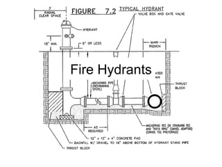
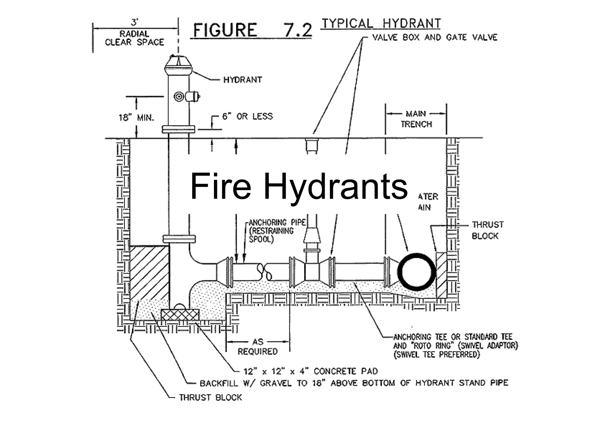
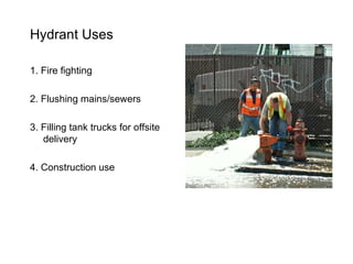
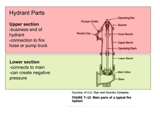
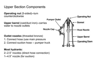
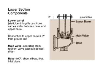
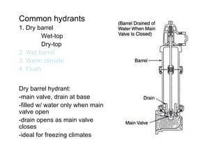
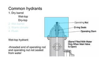
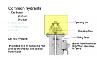
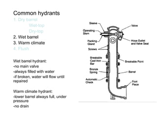
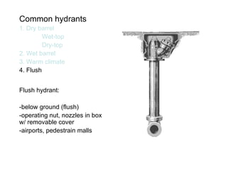
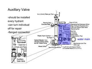
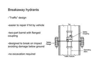
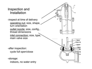
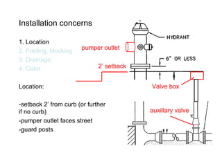
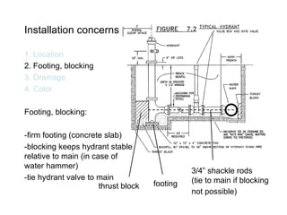
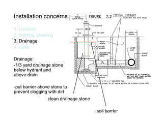
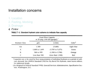
Fire Hydrants
Overview Hydrant Uses Hydrant parts 3.  Types of hydrants 4.  Inspection and installation 5.  Operation and maintenance
Hydrant Uses 1. Fire fighting 2. Flushing mains/sewers 3. Filling tank trucks for offsite delivery 4. Construction use
Hydrant Parts Upper section -business end of  hydrant -connection to fire hose or pump truck Lower section -connects to main -can create negative pressure
Upper Section Components Operating nut  (5-sided)--turn counterclockwise Upper barrel  (cast/duct iron)--carries water to nozzle outlets Outlet nozzles  (threaded bronze) 1. Connect hose (use main pressure 2. Connect suction hose -- pumper truck Most hydrants:   2--2.5” nozzles (direct hose connection) 1--4.5” nozzle (for suction)
Lower Section Components Lower barrel  (static/centrifugally cast iron): carries water between base and upper barrel Connection to upper barrel > 2” from ground line Main valve --operating stem, resilient valve gasket (see next slide) Base --AKA: shoe, elbow, foot, inlet piece ground line 2”
Common hydrants 1. Dry barrel Wet-top Dry-top 2. Wet barrel 3. Warm climate 4. Flush Dry barrel hydrant: -main valve, drain at base -filled w/ water only when main valve open -drain opens as main valve closes -ideal for freezing climates
Common hydrants 1. Dry barrel Wet-top Dry-top 2. Wet barrel 3. Warm climate 4. Flush Wet-top hydrant: -threaded end of operating rod and operating nut not sealed from water
Common hydrants 1. Dry barrel Wet-top Dry-top 2. Wet barrel 3. Warm climate 4. Flush Dry-top hydrant: -threaded end of operating rod and operating nut are sealed from water
Common hydrants 1. Dry barrel Wet-top Dry-top 2. Wet barrel 3. Warm climate 4. Flush Wet barrel hydrant: -no main valve -always filled with water -if broken, water will flow until repaired Warm climate hydrant: -lower barrel always full, under pressure -no drain
Common hydrants 1. Dry barrel Wet-top Dry-top 2. Wet barrel 3. Warm climate 4. Flush Flush hydrant: -below ground (flush) -operating nut, nozzles in box w/ removable cover -airports, pedestrain malls
Dry hydrant main valves 1. Standard compression 2. Slide gate 3. Toggle Standard compression:  -sealed by upward water pressure from main on valve seal ring -turning operating stem pushes lower valve plate down--water comes up!
Dry hydrant main valves 1. Standard compression 2. Slide gate 3. Toggle Slide gate:  -simple gate valve -turning operating stem raises gate--allowing water into lower barrel
Dry hydrant main valves 1. Standard compression 2. Slide gate 3. Toggle Toggle:  -valve opens horizontally -operating arms sciscor and pull valve open -lower barrel extends below connection to main
opening fire hydrant valve
Auxillary Valve -should be installed on  every hydrant -can turn individual hydrants off for repair -flanged connection common water main
Breakaway hydrants -”Traffic” design -easier to repair if hit by vehicle -two-part barrel with flanged coupling -designed to break on impact avoiding damage below ground -no excavation required
Inspection and Installation   -inspect at time of delivery  operating nut:  size, shape, turn orientation outlet nozzle:  size, config.,  thread dimensions  inlet connection:  size, type, main valve size -after inspection:  cycle full open/close -storage: indoors, no water entry
Installation concerns 1. Location 2. Footing, blocking 3. Drainage 4. Color Location: -setback 2’ from curb (or further if no curb) -pumper outlet faces street -guard posts 2’ setback auxillary valve Valve box pumper outlet
Installation concerns 1. Location 2. Footing, blocking 3. Drainage 4. Color Footing, blocking: -firm footing (concrete slab) -blocking keeps hydrant stable relative to main (in case of water hammer) -tie hydrant valve to main thrust block 3/4” shackle rods (tie to main if blocking not possible)   footing
Installation concerns 1. Location 2. Footing, blocking 3. Drainage 4. Color Drainage: -1/3 yard drainage stone  below hydrant and  above drain -put barrier above stone to prevent clogging with dirt clean drainage stone soil barrier
Installation concerns 1. Location 2. Footing, blocking 3. Drainage 4. Color Color: -visible colors -reflective paint -color coding capacity
Installation concerns 1. Location 2. Footing, blocking 3. Drainage 4. Color
Hydrant Maintenance -inspected annually, twice annually in cold climates -make sure dry before winter (in freezing climates) -keep electronic records
End Chapter 9

Chapter9 Hydrant Bradburn

  • 1.
  • 2.
    Overview Hydrant UsesHydrant parts 3. Types of hydrants 4. Inspection and installation 5. Operation and maintenance
  • 3.
    Hydrant Uses 1.Fire fighting 2. Flushing mains/sewers 3. Filling tank trucks for offsite delivery 4. Construction use
  • 4.
    Hydrant Parts Uppersection -business end of hydrant -connection to fire hose or pump truck Lower section -connects to main -can create negative pressure
  • 5.
    Upper Section ComponentsOperating nut (5-sided)--turn counterclockwise Upper barrel (cast/duct iron)--carries water to nozzle outlets Outlet nozzles (threaded bronze) 1. Connect hose (use main pressure 2. Connect suction hose -- pumper truck Most hydrants: 2--2.5” nozzles (direct hose connection) 1--4.5” nozzle (for suction)
  • 6.
    Lower Section ComponentsLower barrel (static/centrifugally cast iron): carries water between base and upper barrel Connection to upper barrel > 2” from ground line Main valve --operating stem, resilient valve gasket (see next slide) Base --AKA: shoe, elbow, foot, inlet piece ground line 2”
  • 7.
    Common hydrants 1.Dry barrel Wet-top Dry-top 2. Wet barrel 3. Warm climate 4. Flush Dry barrel hydrant: -main valve, drain at base -filled w/ water only when main valve open -drain opens as main valve closes -ideal for freezing climates
  • 8.
    Common hydrants 1.Dry barrel Wet-top Dry-top 2. Wet barrel 3. Warm climate 4. Flush Wet-top hydrant: -threaded end of operating rod and operating nut not sealed from water
  • 9.
    Common hydrants 1.Dry barrel Wet-top Dry-top 2. Wet barrel 3. Warm climate 4. Flush Dry-top hydrant: -threaded end of operating rod and operating nut are sealed from water
  • 10.
    Common hydrants 1.Dry barrel Wet-top Dry-top 2. Wet barrel 3. Warm climate 4. Flush Wet barrel hydrant: -no main valve -always filled with water -if broken, water will flow until repaired Warm climate hydrant: -lower barrel always full, under pressure -no drain
  • 11.
    Common hydrants 1.Dry barrel Wet-top Dry-top 2. Wet barrel 3. Warm climate 4. Flush Flush hydrant: -below ground (flush) -operating nut, nozzles in box w/ removable cover -airports, pedestrain malls
  • 12.
    Dry hydrant mainvalves 1. Standard compression 2. Slide gate 3. Toggle Standard compression: -sealed by upward water pressure from main on valve seal ring -turning operating stem pushes lower valve plate down--water comes up!
  • 13.
    Dry hydrant mainvalves 1. Standard compression 2. Slide gate 3. Toggle Slide gate: -simple gate valve -turning operating stem raises gate--allowing water into lower barrel
  • 14.
    Dry hydrant mainvalves 1. Standard compression 2. Slide gate 3. Toggle Toggle: -valve opens horizontally -operating arms sciscor and pull valve open -lower barrel extends below connection to main
  • 15.
  • 16.
    Auxillary Valve -shouldbe installed on every hydrant -can turn individual hydrants off for repair -flanged connection common water main
  • 17.
    Breakaway hydrants -”Traffic”design -easier to repair if hit by vehicle -two-part barrel with flanged coupling -designed to break on impact avoiding damage below ground -no excavation required
  • 18.
    Inspection and Installation -inspect at time of delivery operating nut: size, shape, turn orientation outlet nozzle: size, config., thread dimensions inlet connection: size, type, main valve size -after inspection: cycle full open/close -storage: indoors, no water entry
  • 19.
    Installation concerns 1.Location 2. Footing, blocking 3. Drainage 4. Color Location: -setback 2’ from curb (or further if no curb) -pumper outlet faces street -guard posts 2’ setback auxillary valve Valve box pumper outlet
  • 20.
    Installation concerns 1.Location 2. Footing, blocking 3. Drainage 4. Color Footing, blocking: -firm footing (concrete slab) -blocking keeps hydrant stable relative to main (in case of water hammer) -tie hydrant valve to main thrust block 3/4” shackle rods (tie to main if blocking not possible) footing
  • 21.
    Installation concerns 1.Location 2. Footing, blocking 3. Drainage 4. Color Drainage: -1/3 yard drainage stone below hydrant and above drain -put barrier above stone to prevent clogging with dirt clean drainage stone soil barrier
  • 22.
    Installation concerns 1.Location 2. Footing, blocking 3. Drainage 4. Color Color: -visible colors -reflective paint -color coding capacity
  • 23.
    Installation concerns 1.Location 2. Footing, blocking 3. Drainage 4. Color
  • 24.
    Hydrant Maintenance -inspectedannually, twice annually in cold climates -make sure dry before winter (in freezing climates) -keep electronic records
  • 25.