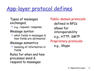
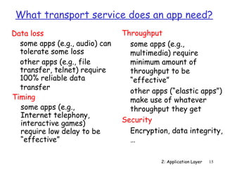
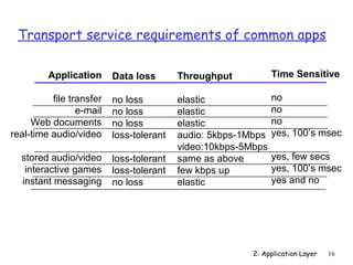
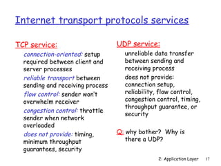
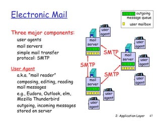
The document discusses the application layer and various network applications. It begins by covering principles of network applications like client-server and peer-to-peer architectures. It then covers specific applications including HTTP and the web, email using SMTP, POP3 and IMAP, and DNS. It also discusses socket programming, addressing processes, and factors applications consider when choosing transport protocols. The document closes by focusing on HTTP and the web in more detail, covering HTTP requests and responses, persistent connections, and the use of cookies and caching to improve performance.

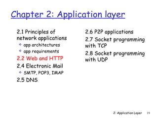
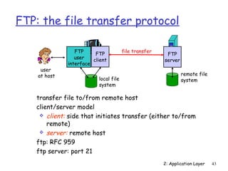
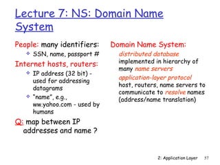
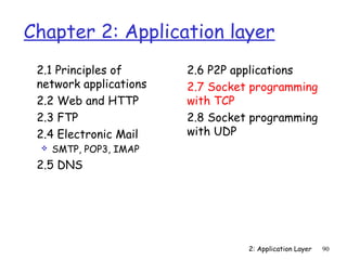
![Internet apps: application, transport protocols
2: Application Layer 18
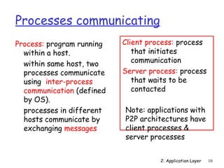
Application
e-mail
remote terminal access
Web
file transfer
streaming multimedia
Internet telephony
Application
layer protocol
SMTP [RFC 2821]
Telnet [RFC 854]
HTTP [RFC 2616]
FTP [RFC 959]
HTTP (eg Youtube),
RTP [RFC 1889]
SIP, RTP, proprietary
(e.g., Skype)
Underlying
transport protocol
TCP
TCP
TCP
TCP
TCP or UDP
typically UDP](https://image.slidesharecdn.com/chapter2l2modifiedum-141126084559-conversion-gate02/85/Chapter2-l2-modified_um-18-320.jpg)
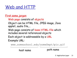
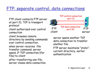
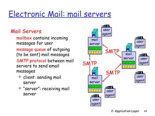
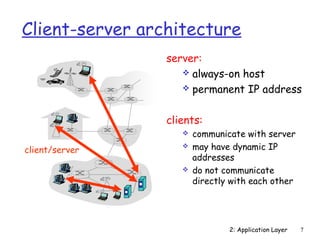
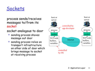
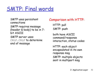
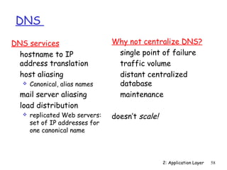
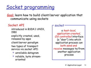
![Electronic Mail: SMTP [RFC 2821]
uses TCP to reliably transfer email message from client
to server, port 25
direct transfer: sending server to receiving server
three phases of transfer
2: Application Layer 49
handshaking (greeting)
transfer of messages
closure
command/response interaction
commands: ASCII text
response: status code and phrase
messages must be in 7-bit ASCII](https://image.slidesharecdn.com/chapter2l2modifiedum-141126084559-conversion-gate02/85/Chapter2-l2-modified_um-49-320.jpg)
![2: Application Layer 53
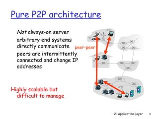
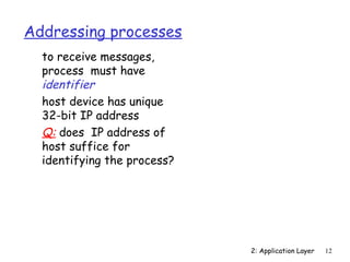
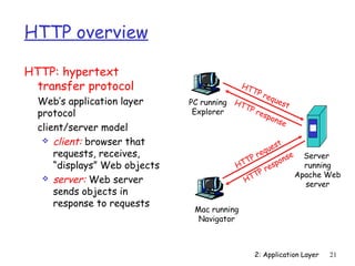
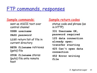
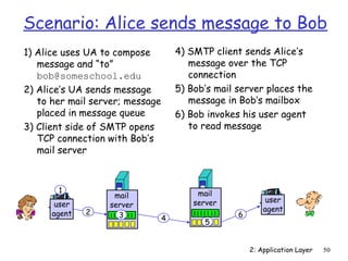
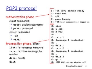
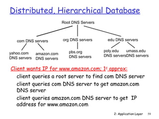
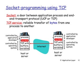
Mail access protocols
SMTP: delivery/storage to receiver’s server
Mail access protocol: retrieval from server
POP: Post Office Protocol [RFC 1939]
• authorization (agent --server) and download
IMAP: Internet Mail Access Protocol [RFC 1730]
• more features (more complex)
• manipulation of stored msgs on server
HTTP: gmail, Hotmail, Yahoo! Mail, etc.
user
agent
sender’s mail
server
user
agent
SMTP SMTP access
protocol
receiver’s mail
server](https://image.slidesharecdn.com/chapter2l2modifiedum-141126084559-conversion-gate02/85/Chapter2-l2-modified_um-53-320.jpg)
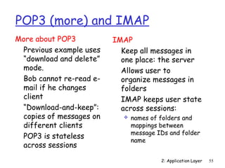
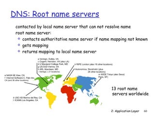
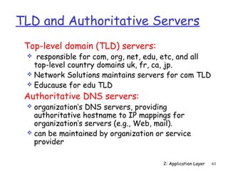
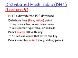
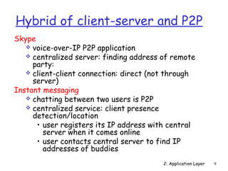
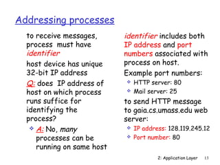
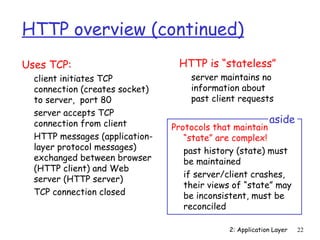
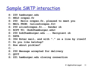
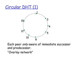
![DHT Identifiers
Assign integer identifier to each peer in range
[0,2n-1].
Each identifier can be represented by n bits.
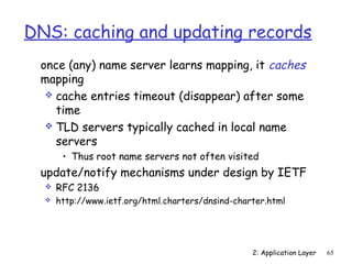
Require each key to be an integer in same range.
To get integer keys, hash original key.
eg, key = h(“Led Zeppelin IV”)
This is why they call it a distributed “hash” table](https://image.slidesharecdn.com/chapter2l2modifiedum-141126084559-conversion-gate02/85/Chapter2-l2-modified_um-84-320.jpg)
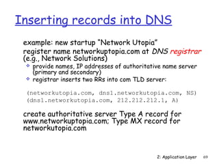
![2: Application Layer 97
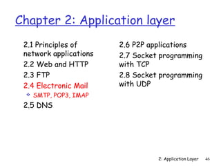
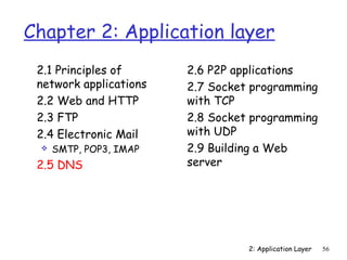
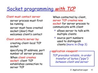
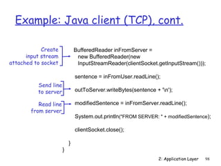
Example: Java client (TCP)
import java.io.*;
import java.net.*;
class TCPClient {
public static void main(String argv[]) throws Exception
{
String sentence;
String modifiedSentence;
BufferedReader inFromUser =
new BufferedReader(new InputStreamReader(System.in));
Socket clientSocket = new Socket(hostname, 6789);
DataOutputStream outToServer =
new DataOutputStream(clientSocket.getOutputStream());
Create
input stream
Create
client socket,
connect to server
Create
output stream
attached to socket](https://image.slidesharecdn.com/chapter2l2modifiedum-141126084559-conversion-gate02/85/Chapter2-l2-modified_um-97-320.jpg)
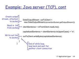
![2: Application Layer 99
Example: Java server (TCP)
import java.io.*;
import java.net.*;
class TCPServer {
public static void main(String argv[]) throws Exception
{
String clientSentence;
String capitalizedSentence;
ServerSocket welcomeSocket = new ServerSocket(6789);
while(true) {
Socket connectionSocket = welcomeSocket.accept();
BufferedReader inFromClient =
new BufferedReader(new
InputStreamReader(connectionSocket.getInputStream()));
Create
welcoming socket
at port 6789
Wait, on welcoming
socket for contact
by client
Create input
stream, attached
to socket](https://image.slidesharecdn.com/chapter2l2modifiedum-141126084559-conversion-gate02/85/Chapter2-l2-modified_um-99-320.jpg)
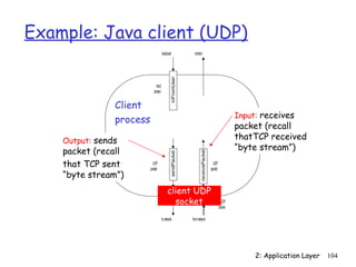
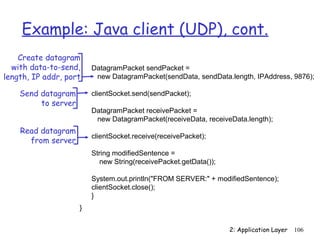
![2: Application Layer 105
Example: Java client (UDP)
import java.io.*;
import java.net.*;
class UDPClient {
public static void main(String args[]) throws Exception
{
BufferedReader inFromUser =
new BufferedReader(new InputStreamReader(System.in));
DatagramSocket clientSocket = new DatagramSocket();
InetAddress IPAddress = InetAddress.getByName(hostname);
byte[] sendData = new byte[1024];
byte[] receiveData = new byte[1024];
String sentence = inFromUser.readLine();
sendData = sentence.getBytes();
Create
input stream
Create
client socket
Translate
hostname to IP
address using DNS](https://image.slidesharecdn.com/chapter2l2modifiedum-141126084559-conversion-gate02/85/Chapter2-l2-modified_um-105-320.jpg)
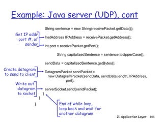
![2: Application Layer 107
Example: Java server (UDP)
import java.io.*;
import java.net.*;
class UDPServer {
public static void main(String args[]) throws Exception
{
DatagramSocket serverSocket = new DatagramSocket(9876);
byte[] receiveData = new byte[1024];
byte[] sendData = new byte[1024];
while(true)
{
DatagramPacket receivePacket =
new DatagramPacket(receiveData, receiveData.length);
serverSocket.receive(receivePacket);
Create
datagram socket
at port 9876
Create space for
received datagram
Receive
datagram](https://image.slidesharecdn.com/chapter2l2modifiedum-141126084559-conversion-gate02/85/Chapter2-l2-modified_um-107-320.jpg)