The document provides an overview of dams, including:
1) Dams are constructed to impound water for uses like flood control, water supply, irrigation, and energy generation. This document focuses on earthen dams, which make up most structures.
2) Dams are built across watershed valleys to collect and store runoff water from rainfall and snowmelt, then release it at a controlled rate. They help regulate water levels and flows downstream.
3) The main types of dams are earthen embankment dams and concrete gravity or arch dams. Earthen dams rely on their mass and low permeability, while concrete dams use their shape and weight to withstand water pressure.
Hydraulic failures .... 40%
Seepage failures…….. 30%
Structural failures .... 30%
(1) Overtopping
(2) Erosion of u/s slope by waves
(3) Erosion of d/s slope by wind and rain
(4) Erosion of d/s toe
(5) Frost action
(1) Overtopping = the design flood is under estimated.
spillway capacity is not adequet
spillway gates are not properly operated
free board is not sufficient
excessive settlement of the foundation and dam
(2) Erosion of u/s slope by waves = The waves developed near the top water surface due to the winds, try to notch out the soil from the upstream face and may even, sometimes, cause the slip of the upstream slope.
Upstream stone pitching or riprap should, therefore, be provided to avoid such failures.
(3) Erosion of d/s slope by wind and rain = The rainwater flowing down the slope; may result in the formation of 'gullies' on the downstream slope thus damaging the dam which may generally lead to partial failure of the dam or in some cases it may cause complete failure of the dam.
Erosion of d/s toe : = Toe erosion may occur due to two reasons :
erosion due to tail water
erosion due to cross currents that may come from spillway buckets.
Frost action : = If the earth dam is located at a place where the temperature falls below the freezing point, frost may form in the pores of the soil in the earth dam.
When there is heaving, the cracks may form in the soil. This may lead to dangerous seepage and consequent failure.
Seepage failures : = Seepage failures may occur due to the following causes :
(1) Piping through the foundation
(2) Piping through the dam
(3) Sloughing of d/s toe
Structural failures :=
Structural failures in earth dams are generally shear failures leading to sliding of the tents or the foundations.
(1) u/s and d/s slope failures due to construction pore pressures
(2) u/s slope failure due to sudden drawdown
(3) D/s slope failure due to steady seepage
(4) Foundation slide due to spontaneous liquefaction
(5) Failure due to earthquake
(6) Failure by spreading
(7) Slope protection failures
(8) Failure due to damage caused by borrowing animals
(9) Failure due to holes caused by leaching of water soluable salts
Criteria for safe Design of Earth Dam :
Section of an Earth Dam :
The design of an earth dam essentially consists of determining such a cross section
the dam which when constructed with the available materials will fulfill its required
tion with adequate safety. Thus there are two aspects of the design of an earth dam.
Engineering geologists provide the basic geological and geotechnical recommendations based on certain details analysis, and design associated surveys. These structures include dams as a major construction project. This lessons highlights the various aspects related to dams, types of dams and the causes of failure of dams.
This power point Presentation explains Engineering Geology of Dams & Reservoirs .Also explains the influence of geological conditions on choice & types of the Dams
Design Principles that are involved in the Design of Flow over an Ogee Crest ...Venkataraju Badanapuri
The ogee-crested spillway’s ability to pass flows efficiently and safely, when properly designed and constructed, with
relatively good flow measuring capabilities, has enabled engineers to use it in a wide variety of situations as a water discharge structure
(USACE, 1988; USBR, 1973). The ogee-crested spillway’s performance attributes are due to its shape being derived from the lower surface of an aerated nappe flowing over a sharp-crested weir.
Final project report on grocery store management system..pdfKamal Acharya
In today’s fast-changing business environment, it’s extremely important to be able to respond to client needs in the most effective and timely manner. If your customers wish to see your business online and have instant access to your products or services.
Online Grocery Store is an e-commerce website, which retails various grocery products. This project allows viewing various products available enables registered users to purchase desired products instantly using Paytm, UPI payment processor (Instant Pay) and also can place order by using Cash on Delivery (Pay Later) option. This project provides an easy access to Administrators and Managers to view orders placed using Pay Later and Instant Pay options.
In order to develop an e-commerce website, a number of Technologies must be studied and understood. These include multi-tiered architecture, server and client-side scripting techniques, implementation technologies, programming language (such as PHP, HTML, CSS, JavaScript) and MySQL relational databases. This is a project with the objective to develop a basic website where a consumer is provided with a shopping cart website and also to know about the technologies used to develop such a website.
This document will discuss each of the underlying technologies to create and implement an e- commerce website.
NO1 Uk best vashikaran specialist in delhi vashikaran baba near me online vas...Amil Baba Dawood bangali
Contact with Dawood Bhai Just call on +92322-6382012 and we'll help you. We'll solve all your problems within 12 to 24 hours and with 101% guarantee and with astrology systematic. If you want to take any personal or professional advice then also you can call us on +92322-6382012 , ONLINE LOVE PROBLEM & Other all types of Daily Life Problem's.Then CALL or WHATSAPP us on +92322-6382012 and Get all these problems solutions here by Amil Baba DAWOOD BANGALI
#vashikaranspecialist #astrologer #palmistry #amliyaat #taweez #manpasandshadi #horoscope #spiritual #lovelife #lovespell #marriagespell#aamilbabainpakistan #amilbabainkarachi #powerfullblackmagicspell #kalajadumantarspecialist #realamilbaba #AmilbabainPakistan #astrologerincanada #astrologerindubai #lovespellsmaster #kalajaduspecialist #lovespellsthatwork #aamilbabainlahore#blackmagicformarriage #aamilbaba #kalajadu #kalailam #taweez #wazifaexpert #jadumantar #vashikaranspecialist #astrologer #palmistry #amliyaat #taweez #manpasandshadi #horoscope #spiritual #lovelife #lovespell #marriagespell#aamilbabainpakistan #amilbabainkarachi #powerfullblackmagicspell #kalajadumantarspecialist #realamilbaba #AmilbabainPakistan #astrologerincanada #astrologerindubai #lovespellsmaster #kalajaduspecialist #lovespellsthatwork #aamilbabainlahore #blackmagicforlove #blackmagicformarriage #aamilbaba #kalajadu #kalailam #taweez #wazifaexpert #jadumantar #vashikaranspecialist #astrologer #palmistry #amliyaat #taweez #manpasandshadi #horoscope #spiritual #lovelife #lovespell #marriagespell#aamilbabainpakistan #amilbabainkarachi #powerfullblackmagicspell #kalajadumantarspecialist #realamilbaba #AmilbabainPakistan #astrologerincanada #astrologerindubai #lovespellsmaster #kalajaduspecialist #lovespellsthatwork #aamilbabainlahore #Amilbabainuk #amilbabainspain #amilbabaindubai #Amilbabainnorway #amilbabainkrachi #amilbabainlahore #amilbabaingujranwalan #amilbabainislamabad
Explore the innovative world of trenchless pipe repair with our comprehensive guide, "The Benefits and Techniques of Trenchless Pipe Repair." This document delves into the modern methods of repairing underground pipes without the need for extensive excavation, highlighting the numerous advantages and the latest techniques used in the industry.
Learn about the cost savings, reduced environmental impact, and minimal disruption associated with trenchless technology. Discover detailed explanations of popular techniques such as pipe bursting, cured-in-place pipe (CIPP) lining, and directional drilling. Understand how these methods can be applied to various types of infrastructure, from residential plumbing to large-scale municipal systems.
Ideal for homeowners, contractors, engineers, and anyone interested in modern plumbing solutions, this guide provides valuable insights into why trenchless pipe repair is becoming the preferred choice for pipe rehabilitation. Stay informed about the latest advancements and best practices in the field.
Student information management system project report ii.pdfKamal Acharya
Our project explains about the student management. This project mainly explains the various actions related to student details. This project shows some ease in adding, editing and deleting the student details. It also provides a less time consuming process for viewing, adding, editing and deleting the marks of the students.
Hierarchical Digital Twin of a Naval Power SystemKerry Sado
A hierarchical digital twin of a Naval DC power system has been developed and experimentally verified. Similar to other state-of-the-art digital twins, this technology creates a digital replica of the physical system executed in real-time or faster, which can modify hardware controls. However, its advantage stems from distributing computational efforts by utilizing a hierarchical structure composed of lower-level digital twin blocks and a higher-level system digital twin. Each digital twin block is associated with a physical subsystem of the hardware and communicates with a singular system digital twin, which creates a system-level response. By extracting information from each level of the hierarchy, power system controls of the hardware were reconfigured autonomously. This hierarchical digital twin development offers several advantages over other digital twins, particularly in the field of naval power systems. The hierarchical structure allows for greater computational efficiency and scalability while the ability to autonomously reconfigure hardware controls offers increased flexibility and responsiveness. The hierarchical decomposition and models utilized were well aligned with the physical twin, as indicated by the maximum deviations between the developed digital twin hierarchy and the hardware.
CFD Simulation of By-pass Flow in a HRSG module by R&R Consult.pptxR&R Consult
CFD analysis is incredibly effective at solving mysteries and improving the performance of complex systems!
Here's a great example: At a large natural gas-fired power plant, where they use waste heat to generate steam and energy, they were puzzled that their boiler wasn't producing as much steam as expected.
R&R and Tetra Engineering Group Inc. were asked to solve the issue with reduced steam production.
An inspection had shown that a significant amount of hot flue gas was bypassing the boiler tubes, where the heat was supposed to be transferred.
R&R Consult conducted a CFD analysis, which revealed that 6.3% of the flue gas was bypassing the boiler tubes without transferring heat. The analysis also showed that the flue gas was instead being directed along the sides of the boiler and between the modules that were supposed to capture the heat. This was the cause of the reduced performance.
Based on our results, Tetra Engineering installed covering plates to reduce the bypass flow. This improved the boiler's performance and increased electricity production.
It is always satisfying when we can help solve complex challenges like this. Do your systems also need a check-up or optimization? Give us a call!
Work done in cooperation with James Malloy and David Moelling from Tetra Engineering.
More examples of our work https://www.r-r-consult.dk/en/cases-en/
Overview of the fundamental roles in Hydropower generation and the components involved in wider Electrical Engineering.
This paper presents the design and construction of hydroelectric dams from the hydrologist’s survey of the valley before construction, all aspects and involved disciplines, fluid dynamics, structural engineering, generation and mains frequency regulation to the very transmission of power through the network in the United Kingdom.
Author: Robbie Edward Sayers
Collaborators and co editors: Charlie Sims and Connor Healey.
(C) 2024 Robbie E. Sayers
1. 9
CHAPTER
2
Chapter 2:
Introduction to Dams
2.0 General
The purpose of a dam is to impound
(store) water for any of several reasons,
e.g., flood control, water supply for
humans or livestock, irrigation, energy
generation, recreation, or pollution
control. This manual primarily concen-
trates on earthen dams, which constitute
the majority of structures in place and
under development in Texas.
2.1 The
Watershed System
Water from rainfall or snowmelt
naturally runs downhill into a stream
valley and then into larger streams or other
bodies of water. The “watershed system”
refers to the drainage process through
which rainfall or snowmelt is collected
water flowing is normally controlled, very
high runoffs (floods) and very low runoffs
(drought periods) are avoided.
2.2 Types of Dams
Dams may either be human-built or
result from natural phenomena, such as
landslides or glacial deposition. The
majority of dams are human structures
normally constructed of earthfill or
concrete. Naturally occurring lakes may
also be modified by adding a spillway to
allow for safe, efficient release of excess
water from the resulting reservoir.
Dam owners should be aware of:
■ the different types of dams
■ essential components of a dam
■ how the components function, and
■ important physical conditions likely to
affect a dam.
Human-built dams may be classified
according to the type of construction
materials used, the methods used in construc-
tion, their slope or cross-section, the way
they resist the forces of the water pressure
behind them, the means of controlling
seepage, and occasionally, their purpose.
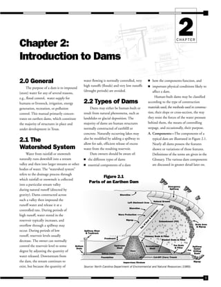
A. Components—The components of a
typical dam are illustrated in Figure 2.1.
Nearly all dams possess the features
shown or variations of those features.
Definitions of the terms are given in the
Glossary. The various dam components
are discussed in greater detail later on.
Impervious Stratum
Foundation Cut-Off (Core) Trench
Bottom
Drain
Spillway Riser
& Trashrack
Freeboard
Upstream
Shell
Spillway Conduit
Core
Downstream
Shell
Blanket Drain & Filter
Toe Drain
& Filter
Toe
Riprap
Spillway
Outlet
Stilling
Basin
Groin Area
& Riprap
Emergency
Spillway
Natural Ground
Left Abutment Area
Shoreline
Wave Protection
T
o
p
o
f
D
a
m
&
R
o
a
d
w
a
y
Embankment (Fill)
Shoreline
Chimney Drain & Filter
Riprap
Figure 2.1
Parts of an Earthen Dam
into a particular stream valley
during natural runoff (directed by
gravity). Dams constructed across
such a valley then impound the
runoff water and release it at a
controlled rate. During periods of
high runoff, water stored in the
reservoir typically increases, and
overflow through a spillway may
occur. During periods of low
runoff, reservoir levels usually
decrease. The owner can normally
control the reservoir level to some
degree by adjusting the quantity of
water released. Downstream from
the dam, the stream continues to
exist, but because the quantity of Source: North Carolina Department of Environmental and Natural Resources (1989).
2. 10 TEXAS COMMISSION ON ENVIRONMENTAL QUALITY
Guidelines for Operation and Maintenance of Dams in Texas
B. Construction Materials— The
materials used for construction of dams
include earth, rock, tailings from mining
or milling, concrete, masonry, steel, and
any combination of tho se materials.
1. Embankment Dams—Embankment
dams, the most common type in use
today, have the general shape shown
in Figure 2.1. Their side slopes
typically have a grade of two to one
(horizontal to vertical) or flatter.
Their capacity for water retention is
due to the low permeability of the
entire mass (in the case of a homoge-
neous embankment) or of a zone of
low-permeability material (in the
case of a zoned embankment dam).
Materials used for embankment
dams include natural soil or rock
obtained from borrow areas or
nearby quarries, or waste materials
obtained from mining or milling. If
the natural material has a high
permeability, then a zone of very-
low-permeability material must be
included in the dam to retain water.
An embankment dam is termed
an “earthfill” or “rockfill” dam
depending on whether it is com-
posed mostly of compacted earth or
mostly of compacted or dumped
pervious rock.
The ability of an embankment
dam to resist the hydrostatic pressure
caused by reservoir water is primarily
the result of the mass, weight, and
strength of its materials.
2. Concrete Dams—Concrete dams may
be categorized into gravity and arch
dams according to the designs used
to resist the stress due to reservoir
water pressure. A concrete gravity
dam (shown in Figure 2.2) is the
most common form of concrete
dam. In it, the mass weight of the
concrete and friction resist the
reservoir water pressure. A buttress
dam is a specific type of gravity dam
in which the large mass of concrete is
reduced, and the forces are diverted
to the dam foundation through
vertical or sloping buttresses. Gravity
dams are constructed of non-
reinforced vertical blocks of concrete
with flexible seals in the joints
between the blocks.
Concrete arch dams are typically
rather thin in cross-section (Figure
2.3). The reservoir water forces
acting on an arch dam are carried
laterally into the abutments. The
shape of the arch may resemble a
segment of a circle or an ellipse, and
the arch may be curved in the
vertical plane as well. Such dams are
usually built from a series of thin
vertical blocks that are keyed
together, with water stops between
the blocks. Variations of arch dams
include multi-arch dams, in which
more than one curved section is used,
and arch gravity dams, which combine
some features of the two types.
A recently developed method for
constructing concrete gravity dams
involves the use of a relatively weak
concrete mix which is placed and
compacted in a manner similar to
that used for earthfill dams. Roller-
compacted concrete has the advan-
tages of decreased cost and time. In
addition, there are no joints where
seepage could occur.
3. Other Types—Various construction
techniques could be used in a single
dam. For example, a dam could
include an earthen or rockfill embank-
ment as well as a portion made of
concrete. In such a case, the concrete
section would normally contain the
spillway or other outlet works.
A recent design for low-head dams
(with a minimal height of water
behind the dam) uses inflatable
rubber or plastic materials anchored
at the bottom by a concrete slab.
Some dams are constructed for
special purposes, such as diversion of
water, or permit construction of
Resistance to Movement
Offered by Key in Foundation
Support Offered
by Foundation
Pressure of
Reservoir
Resistance to Movement
Offered by Abutment
Resistance to Movement
(Friction Between Dam & Foundation)
Figure 2.2
Concrete Gravity Dam
3. 11
TEXAS COMMISSION ON ENVIRONMENTAL QUALITY
Guidelines for Operation and Maintenance of Dams in Texas
other facilities in river valleys. These
dams are called diversion dams and
cofferdams, respectively.
2.3 Water-
Retention Ability
Because the purpose of a dam is to
retain water effectively and safely, its
water-retention ability is of prime impor-
tance. Water may pass from the reservoir
to the downstream side of a dam by:
(1) Seeping through the dam.
(2) Seeping through the abutments.
(3) Seeping under the dam.
(4) Overtopping the dam.
(5) Passing through the outlet works.
(6) Passing through or over a service
(primary) spillway.
(7) Passing over an emergency spillway.
The first three modes are considered
undesirable, particularly if the seepage is
not limited in area or volume. Overtop-
ping of an embankment dam is also very
undesirable because the embankment
material may be eroded away. Additionally,
only few concrete dams have been
designed to be overtopped. Water nor-
mally leaves a dam by passing through an
outlet works or a service spillway; it should
pass over an emergency spillway only
during periods of very high reservoir levels
and high water inflow.
A. Seepage Through a Dam—All
embankment dams and most concrete
dams allow some seepage. The earth or
other material used to construct
embankment dams has some perme-
ability, and water under pressure from
the reservoir will eventually seep
through. However, it is important to
control the quantity of seepage by using
low-permeability materials in construc-
tion and by channeling and restricting
the flow so that embankment materials
do not erode.
Seepage through a concrete dam is
usually minimal and is almost always
through joints between blocks, or
through cracks or deteriorated concrete
which may have developed. Mainte-
nance of these joints and cracks is
therefore essential. The seepage water
should be collected and channelized, so
that its quantity can be measured and
erosion minimized.
B. Seepage Around a Dam—Seepage
under a dam, through the dam
foundation material, or around the
ends of a dam through the abutment
materials may become a serious
problem if the flow is large or of
sufficient velocity to cause erosion.
Seepage under a dam also creates high
hydrostatic uplift (pore-water) pressure,
which has the effect of diminishing the
weight of the dam, making it less stable.
Seepage through abutments or
foundations can dissolve the constitu-
ents of certain rocks such as limestone,
dolomite, or gypsum so that any cracks
or joints in the rock become progres-
sively larger and in turn allow more
seepage. Abutment or foundation
seepage may also result in “piping”
internal erosion, in which the flow of
water is fast enough to erode away small
particles of soil. This erosion progresses
from the water exit point backward to
the entrance point. When that point is
reached, water may then flow without
restriction, resulting in even greater
erosion and probable dam failure.
Obviously, large, unrestricted
seepage is undesirable. To minimize this
possibility, dams are constructed with
internal impermeable barriers and
internal drainage facilities such as
drainpipes or filter systems, or other
drainage systems such as toe, blanket,
or chimney drains.
Flow through a dam foundation
may be diminished by grouting known
or suspected highly permeable material,
constructing a cutoff wall or trench
below a dam, or constructing an
upstream impermeable blanket. Figure
2.1 illustrates a cutoff trench.
In summary, the overall water
retention ability of a dam depends on
its permeability, the abutments, the
foundation, and the efforts made to
reduce that permeability or restrict the
Resistance to Movement
Offered by Key in Foundation
Support Offered
by Foundation
Pressure of
Reservoir
Resistance to Movement
Offered by Abutment
Figure 2.3
Concrete Arch Dam
4. 12 TEXAS COMMISSION ON ENVIRONMENTAL QUALITY
Guidelines for Operation and Maintenance of Dams in Texas
flow of water through these compo-
nents. Should high permeability occur,
seepage can lead to piping, which will
likely result in failure.
2.4 Release
of Water
Intentional release of water, as stated
earlier, is confined to water releases
through a service spillway or outlet works
or over emergency spillways.
A. Service (Principal) or Mechanical
Spillway—The service (principal) or
mechanical spillway maintains the
normal water level in the reservoir. Its
function is to pass expected flood flows
past the dam safely and without
erosion. It may consist of a pipe
through the dam or a system of gates
that discharge water over the top into a
concrete spillway . Either method uses
the overflow principle. When the
reservoir reaches a certain level, water
flows into a standpipe or riser pipe or
over a gate. Intake structures for
spillways must have systems that
prevent clogging by trash or debris.
B. Drawdown Facility—All dams should
have some type of drawdown facility
which can:
• Quickly lower the water level if
failure of the dam is imminent.
• Serve the operational purposes of the
reservoir.
• Lower the water level for dam repairs.
• Purposely fluctuate the pool level to
kill weeds and mosquitoes.
The valve regulating the drawdown
facility should be on the upstream end
of the conduit to minimize the risk to
the dam posed by a possible internal
rupture of the pipe .
C. Emergency (Auxiliary) Spillway—As
the name implies, an emergency
spillway functions during emergency
conditions to prevent overtopping of a
dam. A typical emergency spillway is an
excavated channel in earth or rock near
one abutment of a dam. An emergency
spillway should always discharge away
from the toe of a dam to avoid its
erosion. Furthermore, the spillway
should be constructed in such a manner
that the spillway itself will not seriously
erode when it is in use. Obviously,
erosional failure of the spillway could
be as catastrophic as failure of the dam
itself. An emergency spillway should be
sized to convey the so-called “design
flood”—the rare, large-magnitude flood
used to establish design criteria. The
spillways of many existing dams are
now considered undersized because
standards for the design flood have
increased over the years.