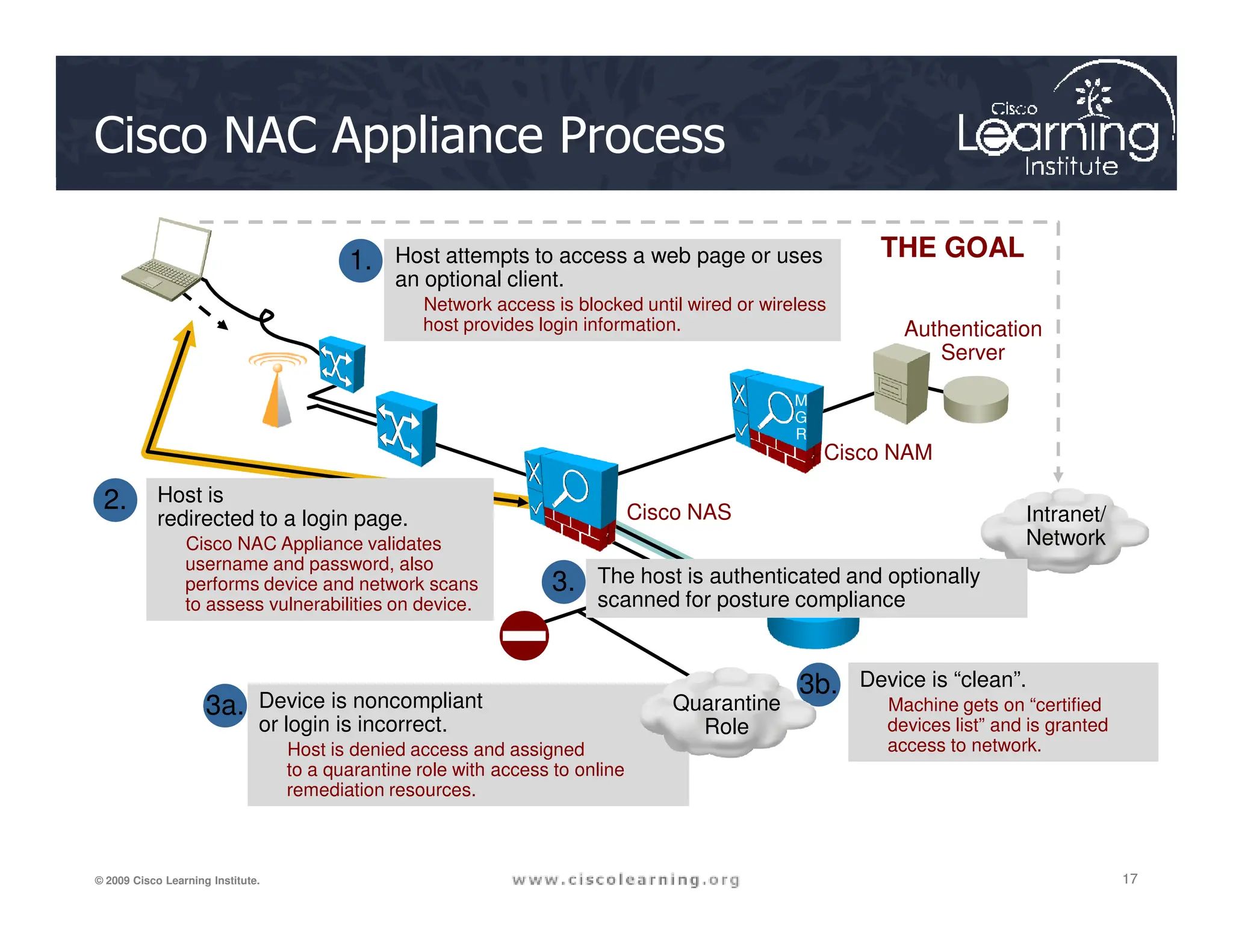
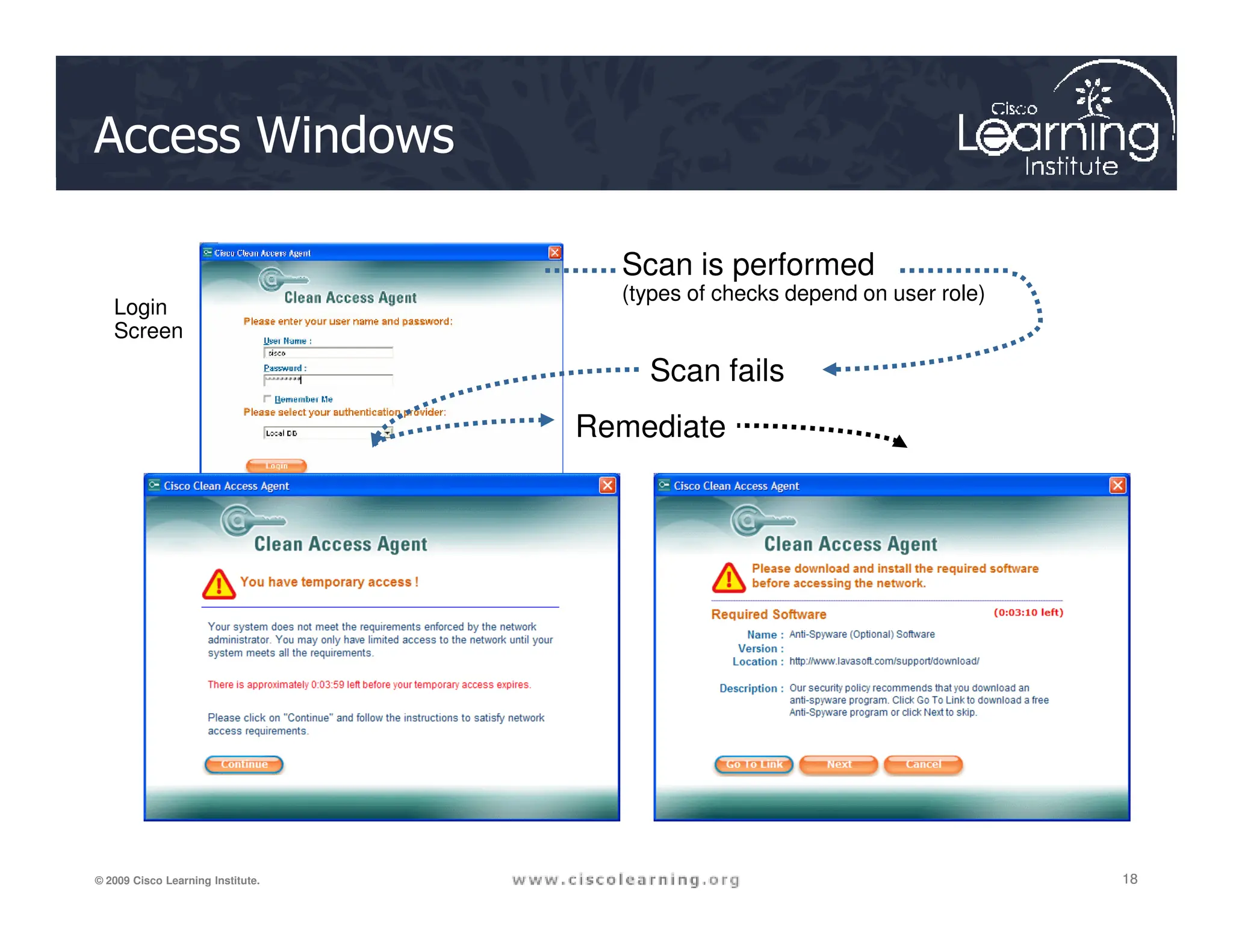
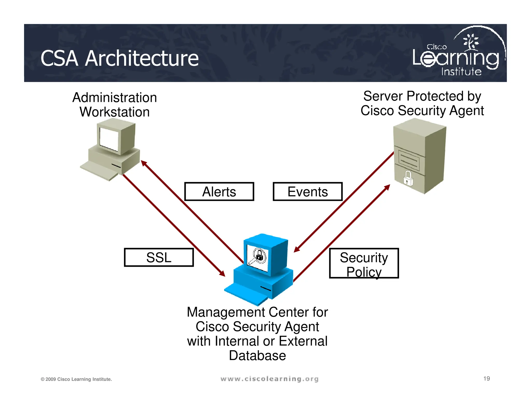
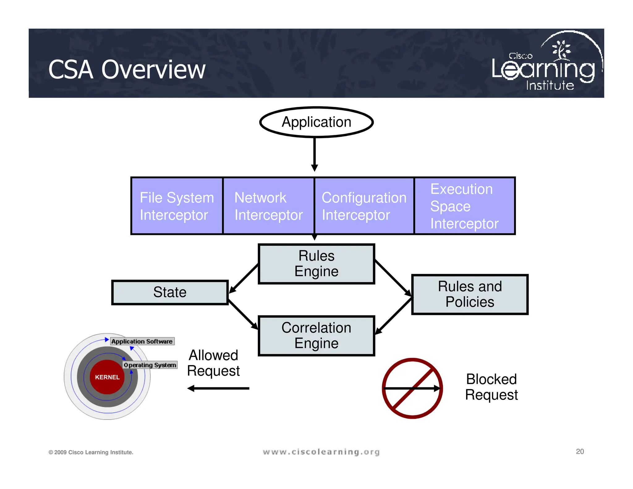
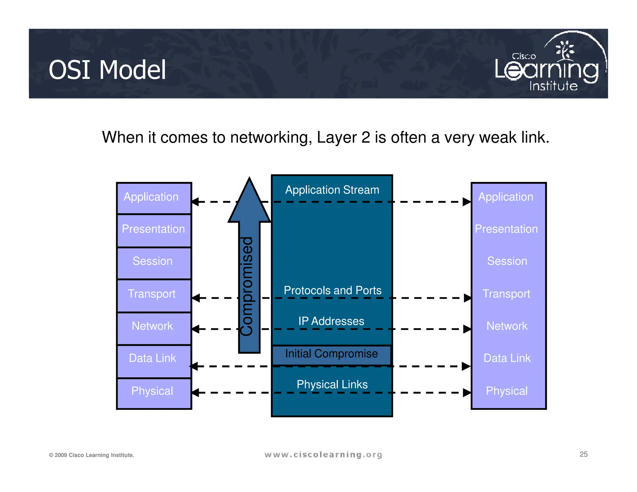
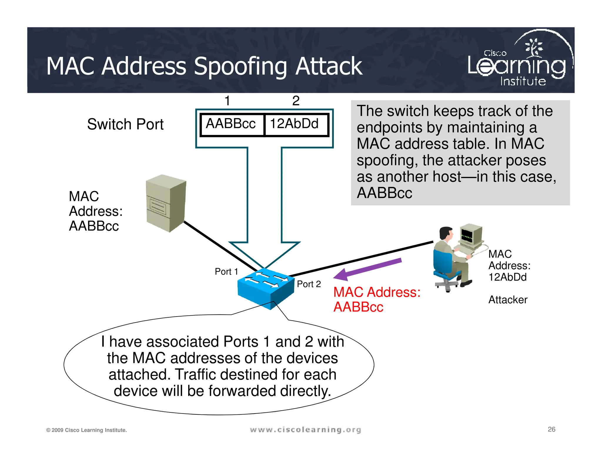
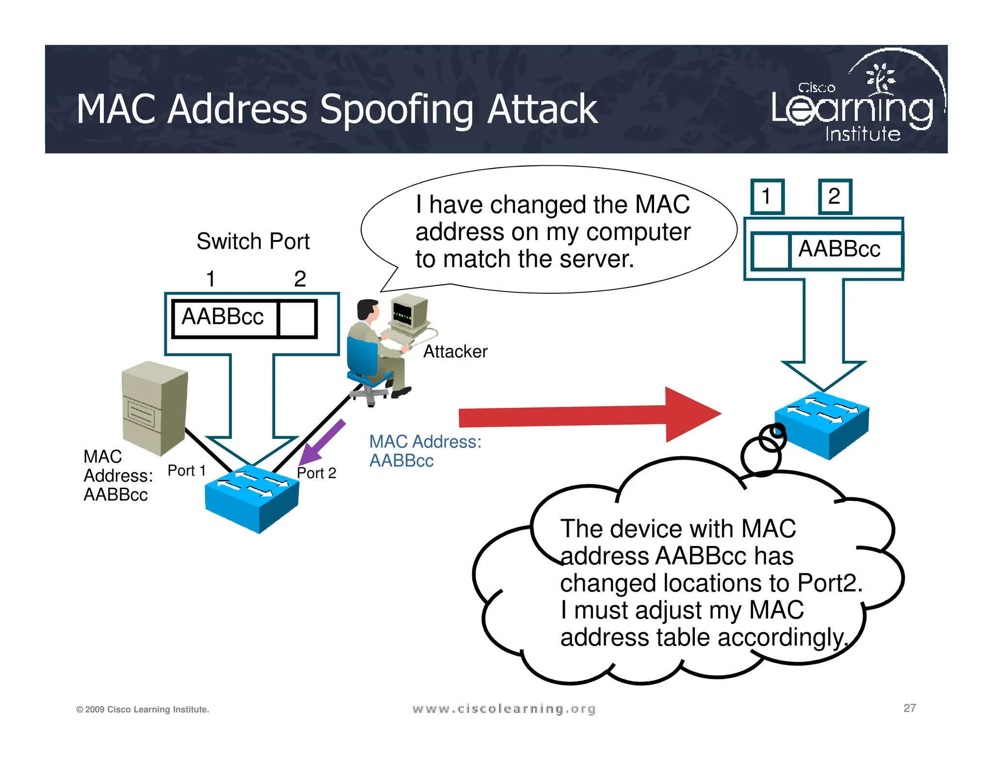
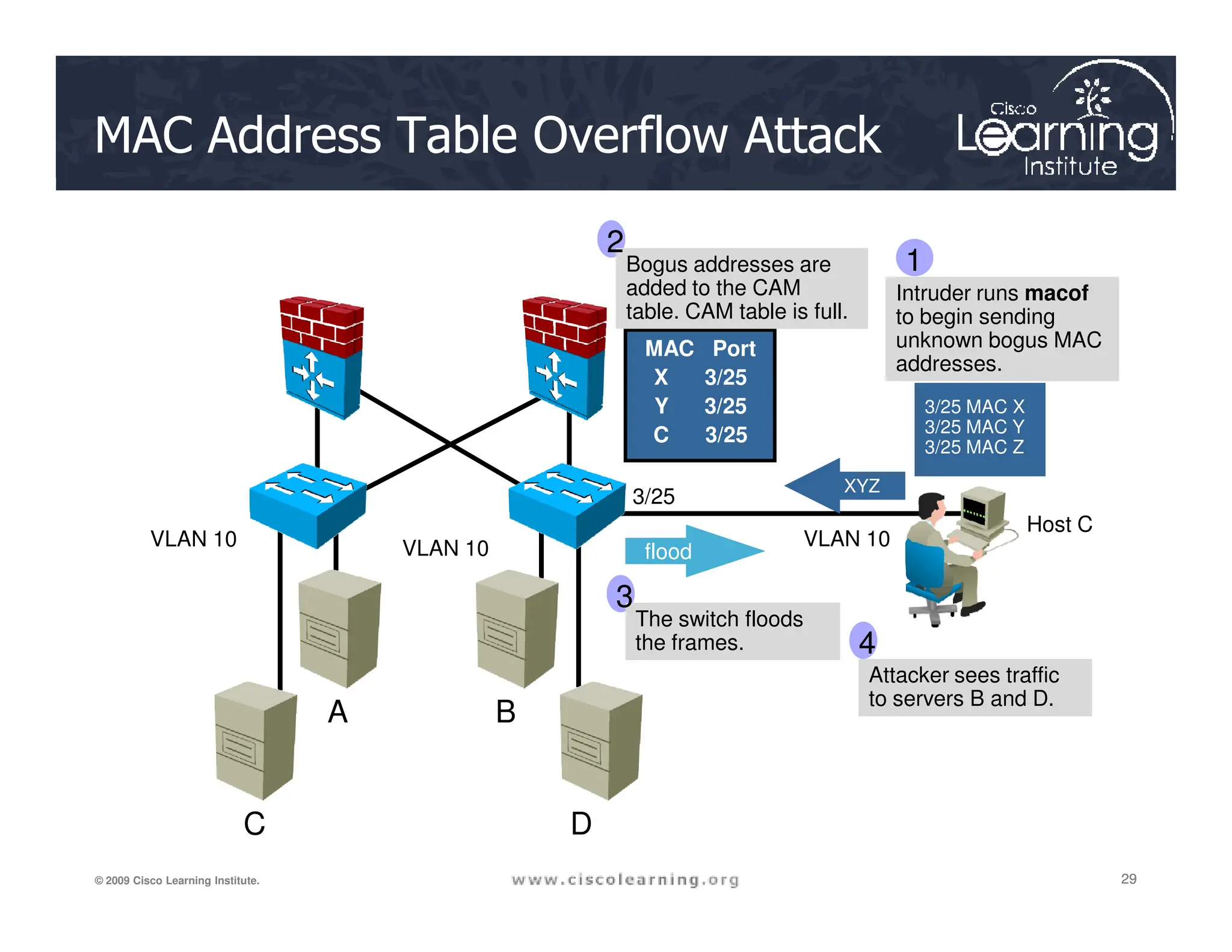
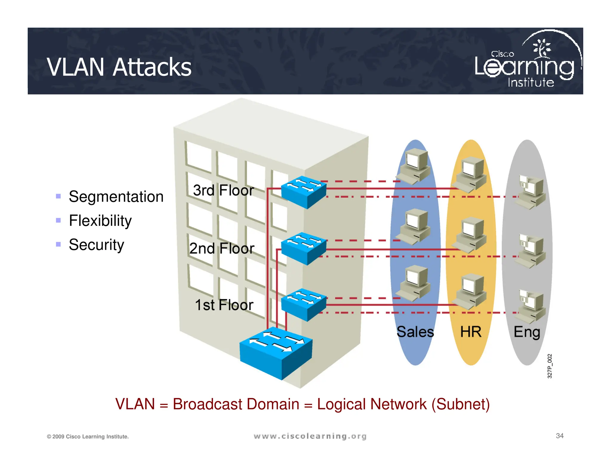
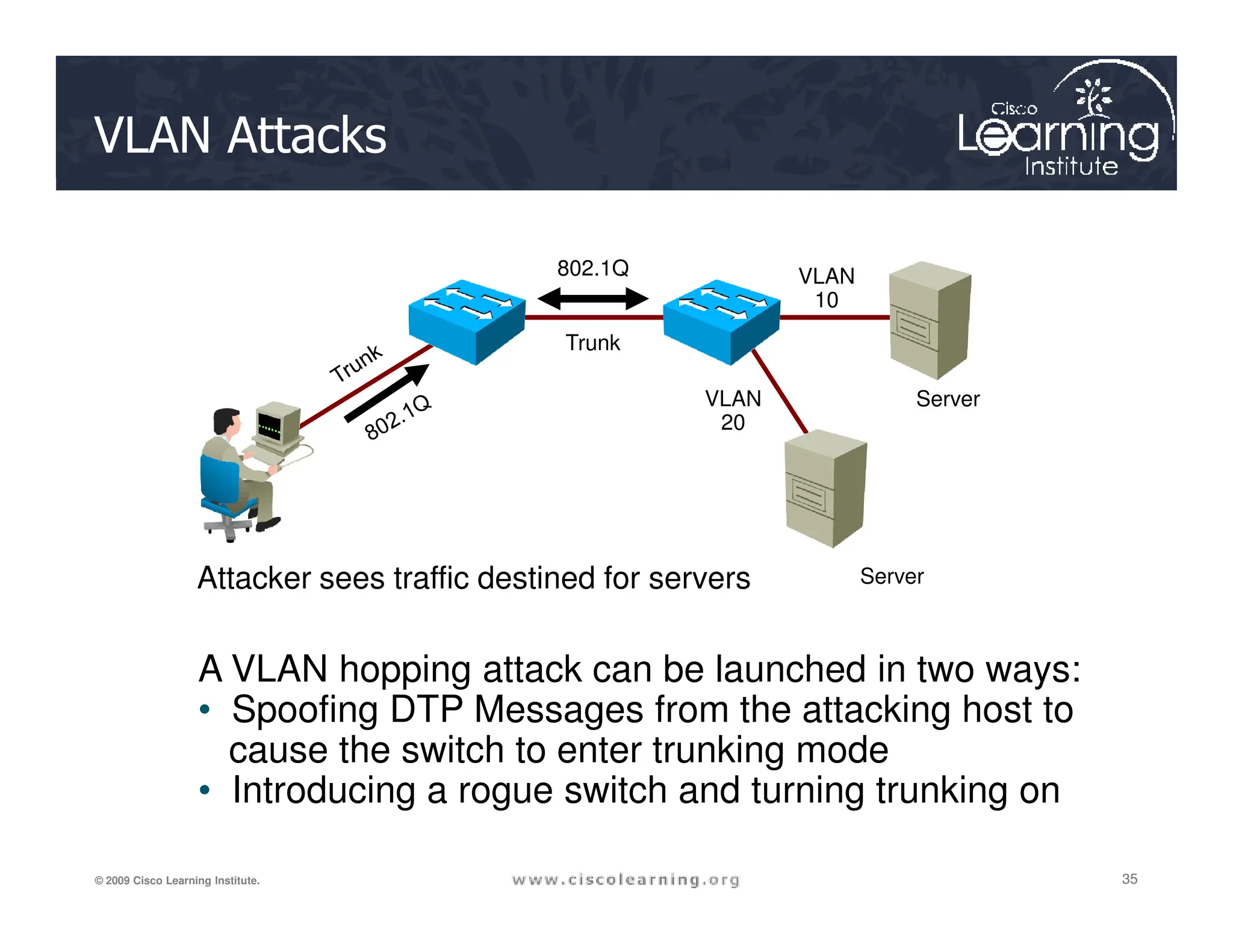
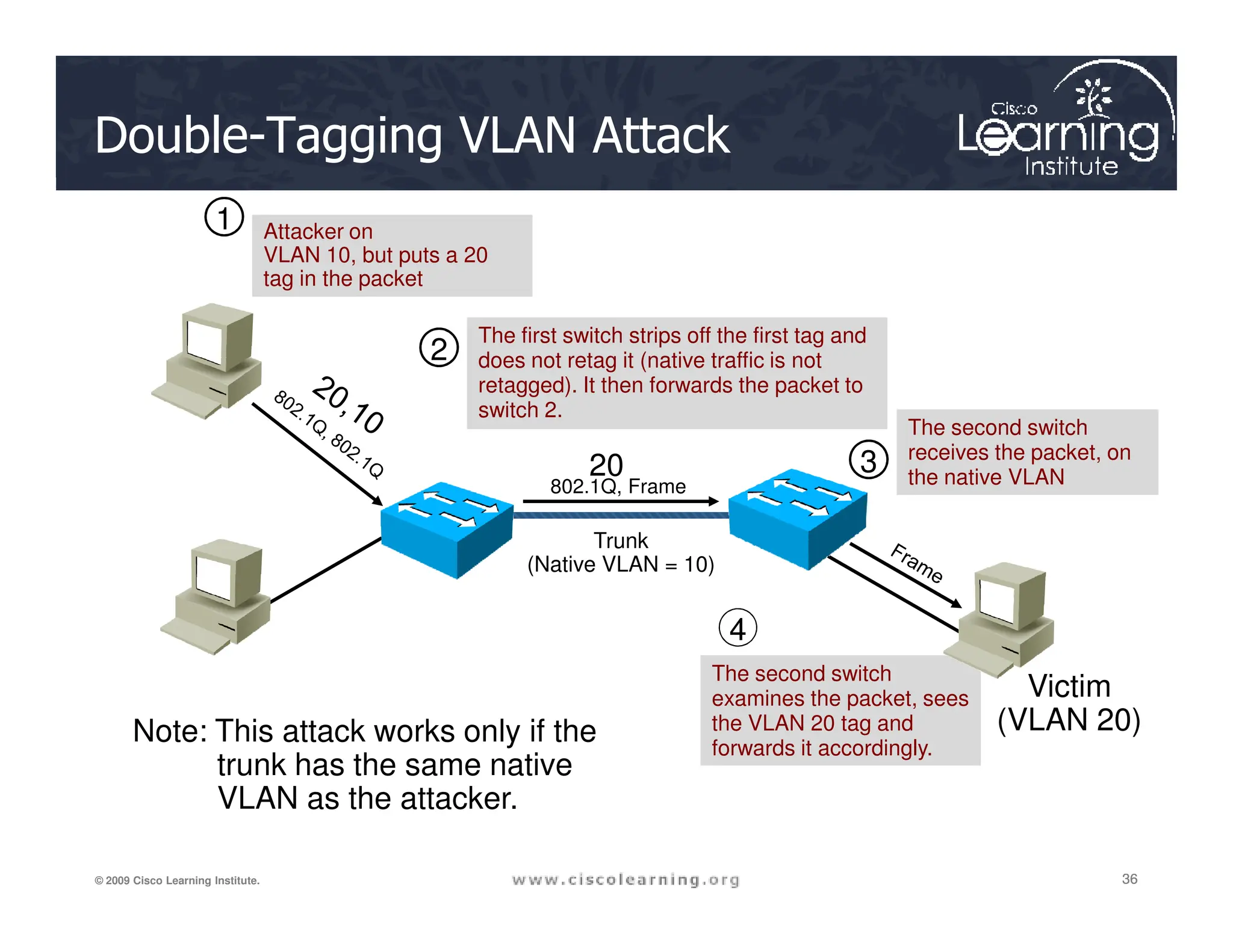
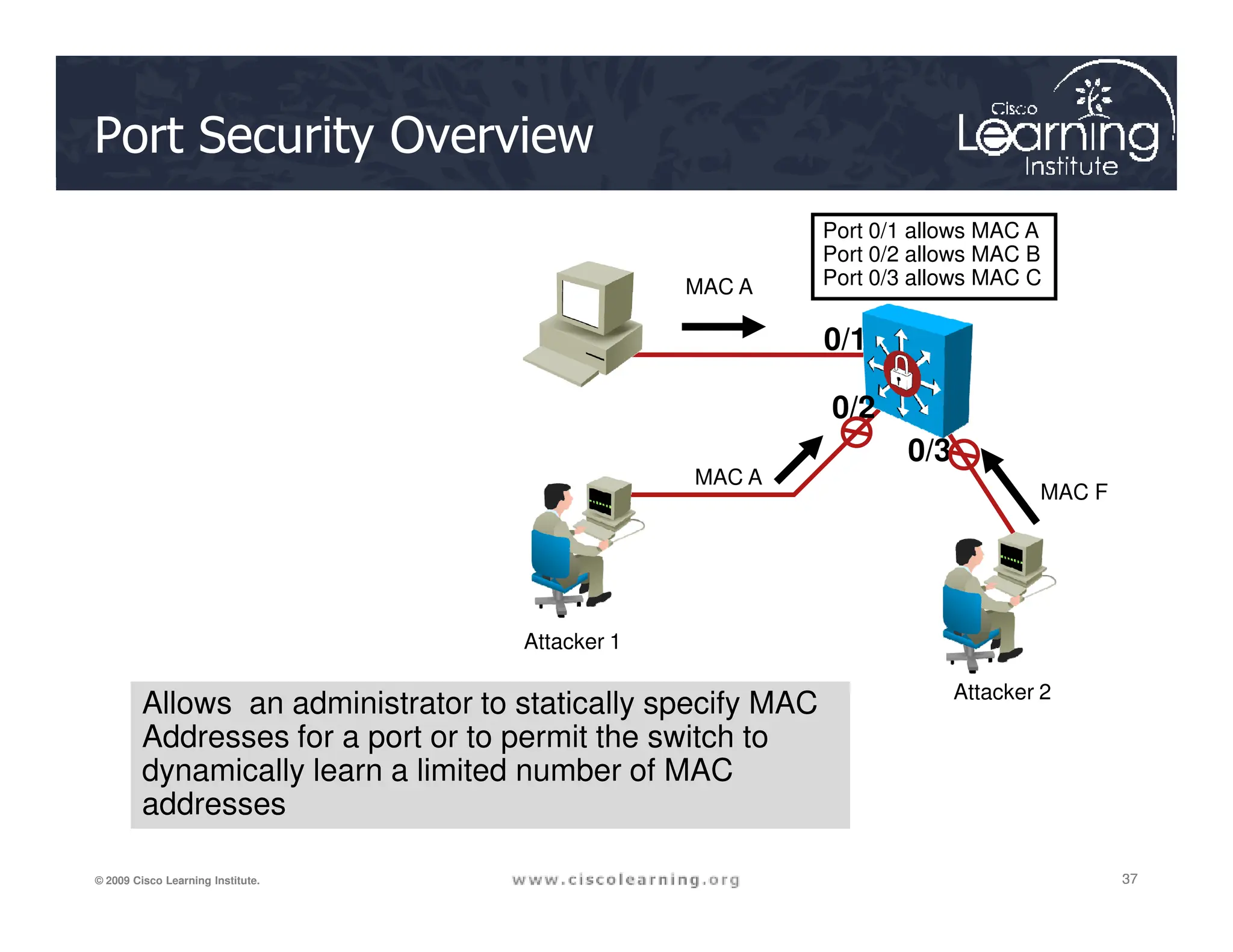
The document outlines comprehensive lessons on securing local area networks (LANs), covering endpoint vulnerabilities, switch security features, and network attack mitigations. It details various security mechanisms including Cisco's endpoint security solutions, network admission control (NAC), port security, storm control, and VLAN attacks. Additionally, it emphasizes best practices for layer 2 security and the fundamental aspects of securing wireless, VoIP, and SAN technologies.


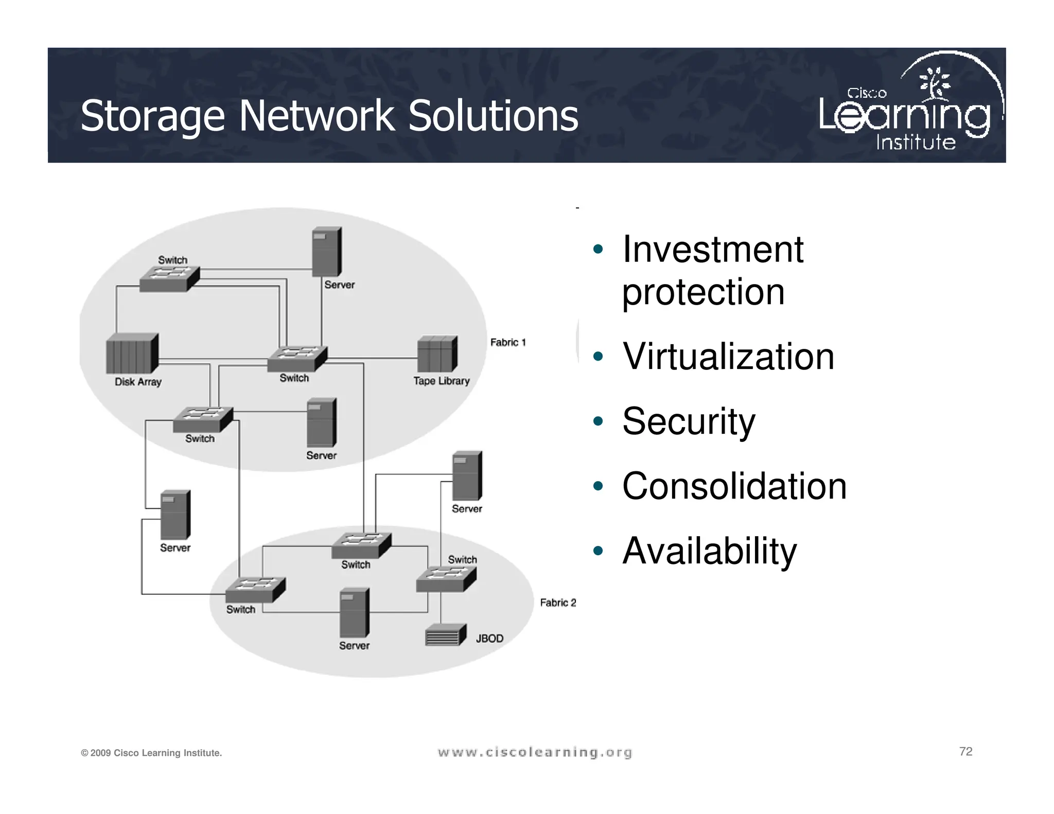
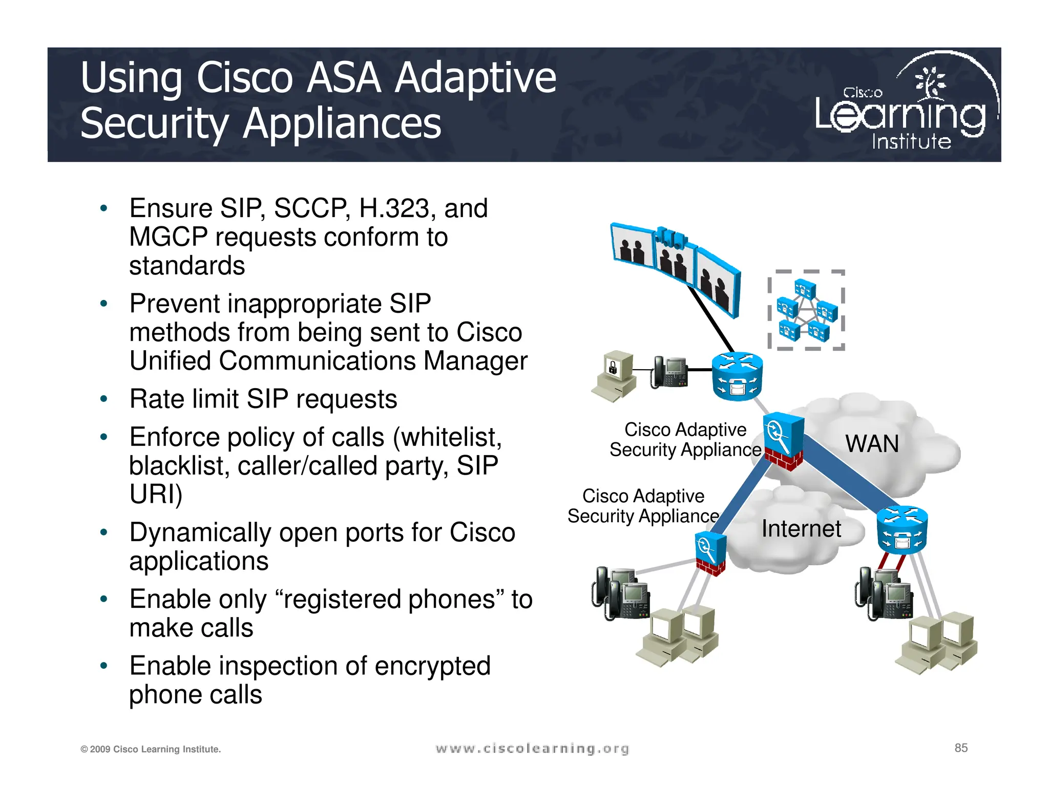
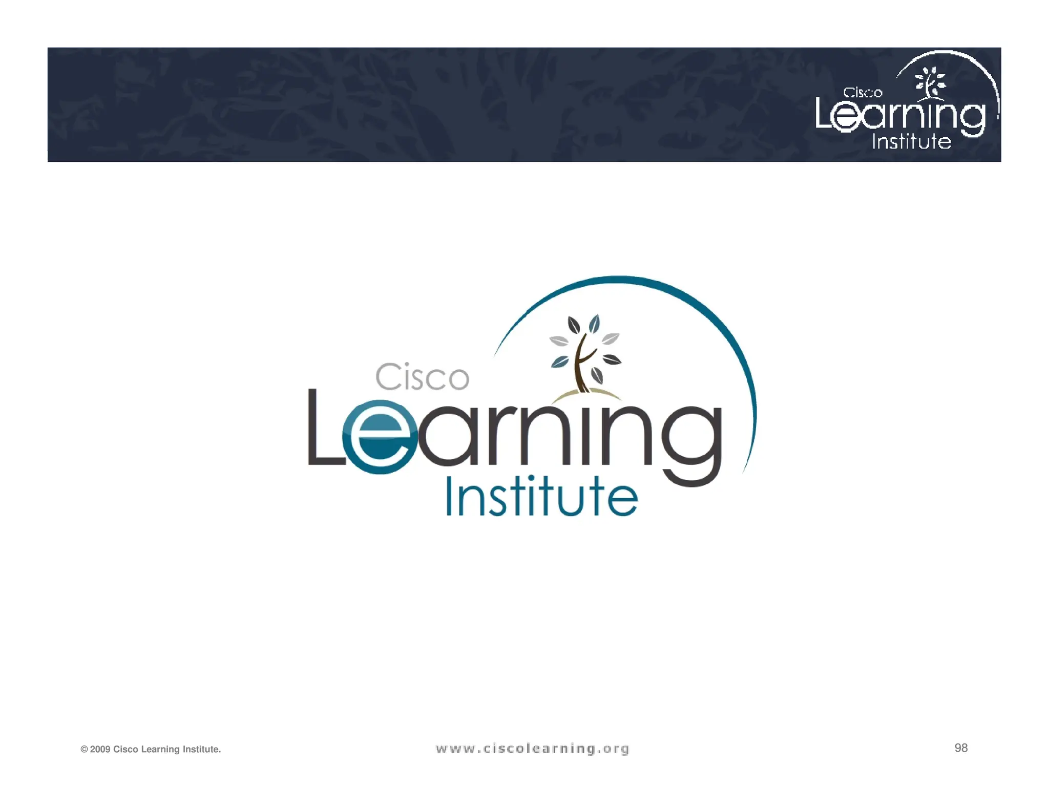
![Switchport Port-Security Parameters
Parameter Description
mac-address mac-address (Optional) Specify a secure MAC address for the port by entering a 48-bit MAC aaddress. You can add additional
secure MAC addresses up to the maximum value configured.
vlan vlan-id (Optional) On a trunk port only, specify the VLAN ID and the MAC address. If no VLAN ID is specified, the native
VLAN is used.
vlan access (Optional) On an access port only, specify the VLAN as an access VLAN.
vlan voice (Optional) On an access port only, specify the VLAN as a voice VLAN
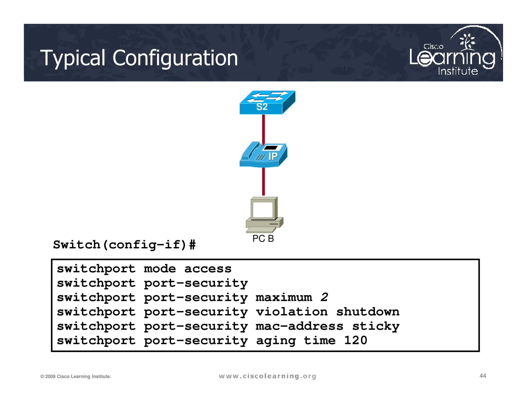
mac-address sticky (Optional) Enable the interface for sticky learning by entering only the mac-address sticky keywords. When sticky
learning is enabled, the interface adds all secure MAC addresses that are dynamically learned to the running
39
39
39
© 2009 Cisco Learning Institute.
[mac-address] learning is enabled, the interface adds all secure MAC addresses that are dynamically learned to the running
configuration and converts these addresses to sticky secure MAC addresses.
Specify a sticky secure MAC address by entering the mac-address sticky mac-address keywords..
maximum value (Optional) Set the maximum number of secure MAC addresses for the interface. The maximum number of secure
MAC addresses that you can configure on a switch is set by the maximum number of available MAC
addresses allowed in the system. The active Switch Database Management (SDM) template determines this
number. This number represents the total of available MAC addresses, including those used for other Layer 2
functions and any other secure MAC addresses configured on interfaces.
The default setting is 1.
vlan [vlan-list] (Optional) For trunk ports, you can set the maximum number of secure MAC addresses on a VLAN. If the vlan
keyword is not entered, the default value is used.
■ vlan: set a per-VLAN maximum value.
■ vlan vlan-list: set a per-VLAN maximum value on a range of VLANs separated by a hyphen or a series of
VLANs separated by commas. For nonspecified VLANs, the per-VLAN maximum value is used.](https://image.slidesharecdn.com/ch6-240712063159-54c98ae1/75/Chapter-6-Securing-the-Local-Area-Network-pdf-39-2048.jpg)

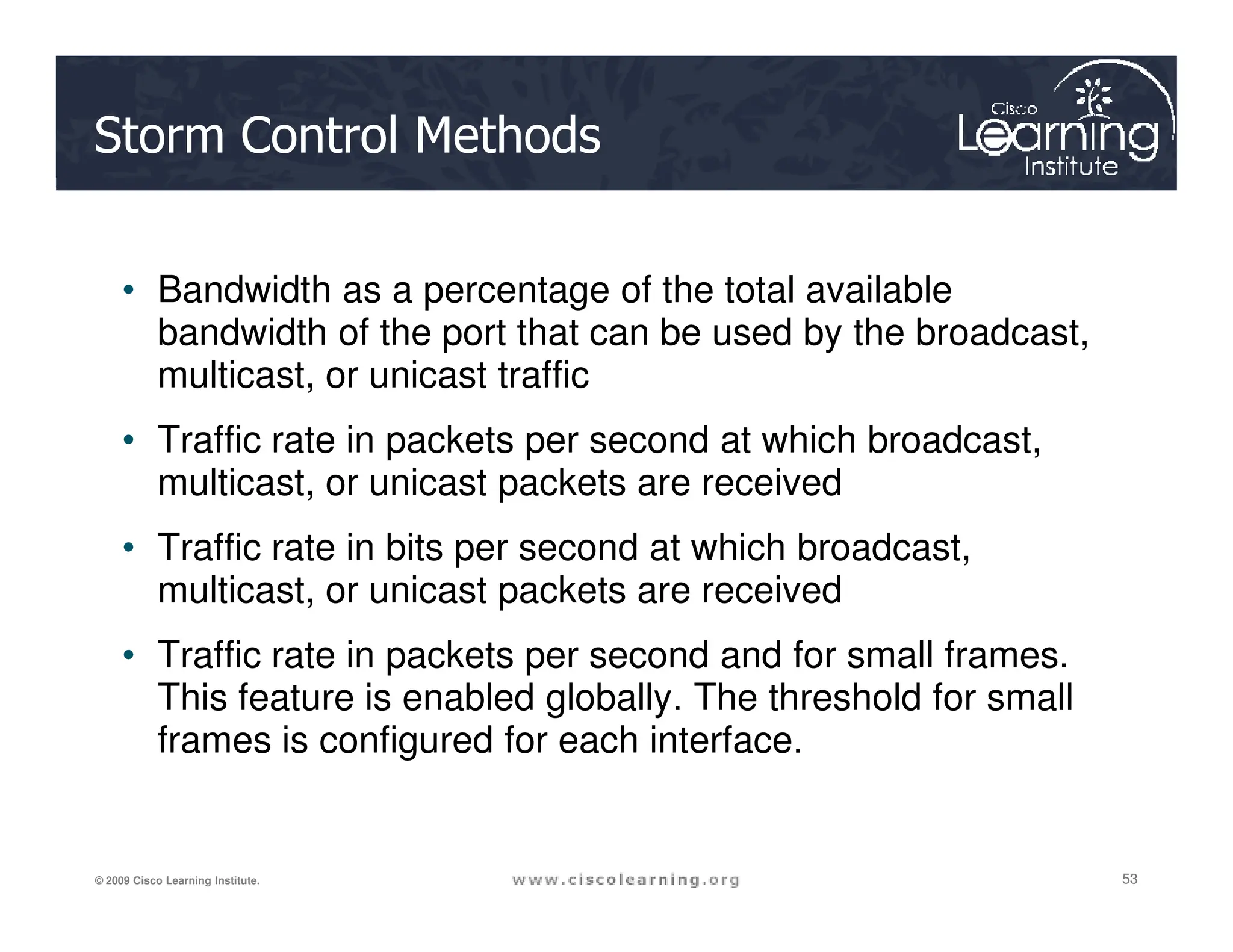
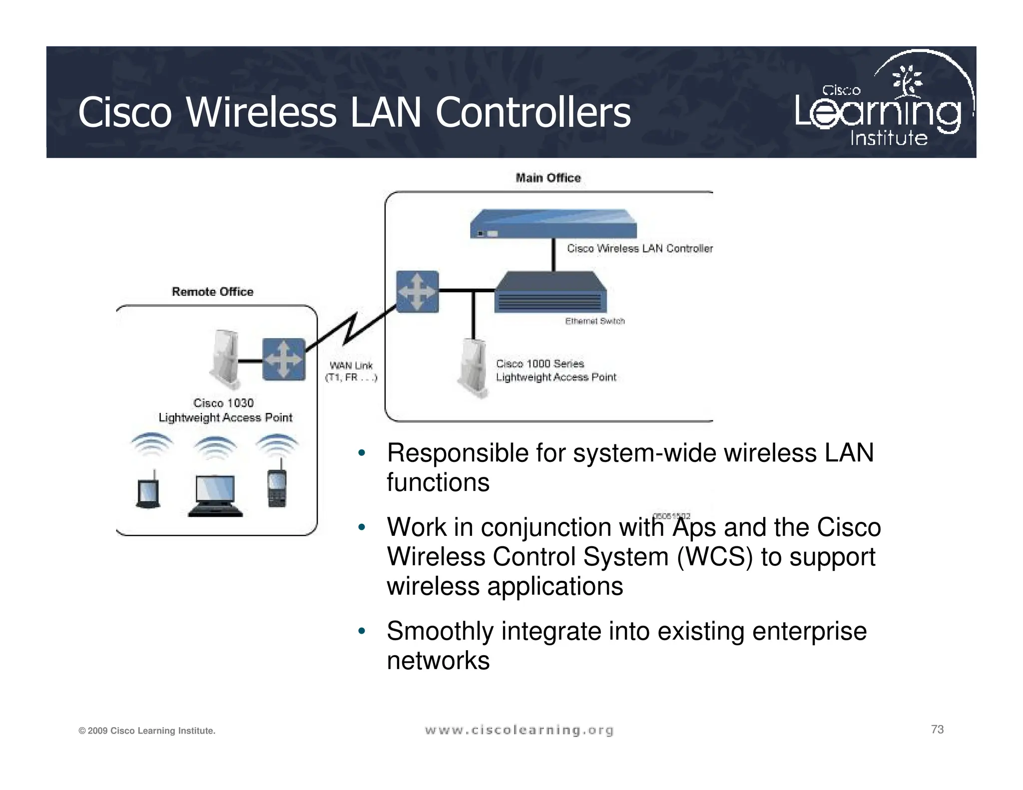
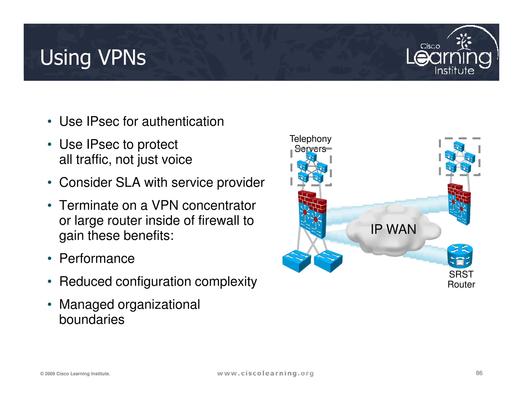
![Storm Control Parameters
Parameter Description
broadcast This parameter enables broadcast storm control on the interface.
multicast This parameter enables multicast storm control on the interface.
unicast This parameter enables unicast storm control on the interface.
level level [level-low] Rising and falling suppression levels as a percentage of total bandwidth of the port.
• level: Rising suppression level. The range is 0.00 to 100.00. Block the flooding of
storm packets when the value specified for level is reached.
• level-low: (Optional) Falling suppression level, up to two decimal places. This
value must be less than or equal to the rising suppression value.
level bps bps [bps-low] Specify the rising and falling suppression levels as a rate in bits per second at which
55
55
55
© 2009 Cisco Learning Institute.
level bps bps [bps-low] Specify the rising and falling suppression levels as a rate in bits per second at which
traffic is received on the port.
• bps: Rising suppression level. The range is 0.0 to 10000000000.0. Block the
flooding of storm packets when the value specified for bps is reached.
• bps-low: (Optional) Falling suppression level, up to one decimal place. This value
must be equal to or less than the rising suppression value.
level pps pps [pps-low] Specify the rising and falling suppression levels as a rate in packets per second at
which traffic is received on the port.
• pps: Rising suppression level. The range is 0.0 to 10000000000.0. Block the
flooding of storm packets when the value specified for pps is reached.
• pps-low: (Optional) Falling suppression level, up to one decimal place. This value
must be equal to or less than the rising suppression value.
action {shutdown|trap} The action taken when a storm occurs on a port. The default action is to filter traffic
and to not send an SNMP trap.
The keywords have these meanings:
• shutdown: Disables the port during a storm
• trap: Sends an SNMP trap when a storm occurs](https://image.slidesharecdn.com/ch6-240712063159-54c98ae1/75/Chapter-6-Securing-the-Local-Area-Network-pdf-55-2048.jpg)

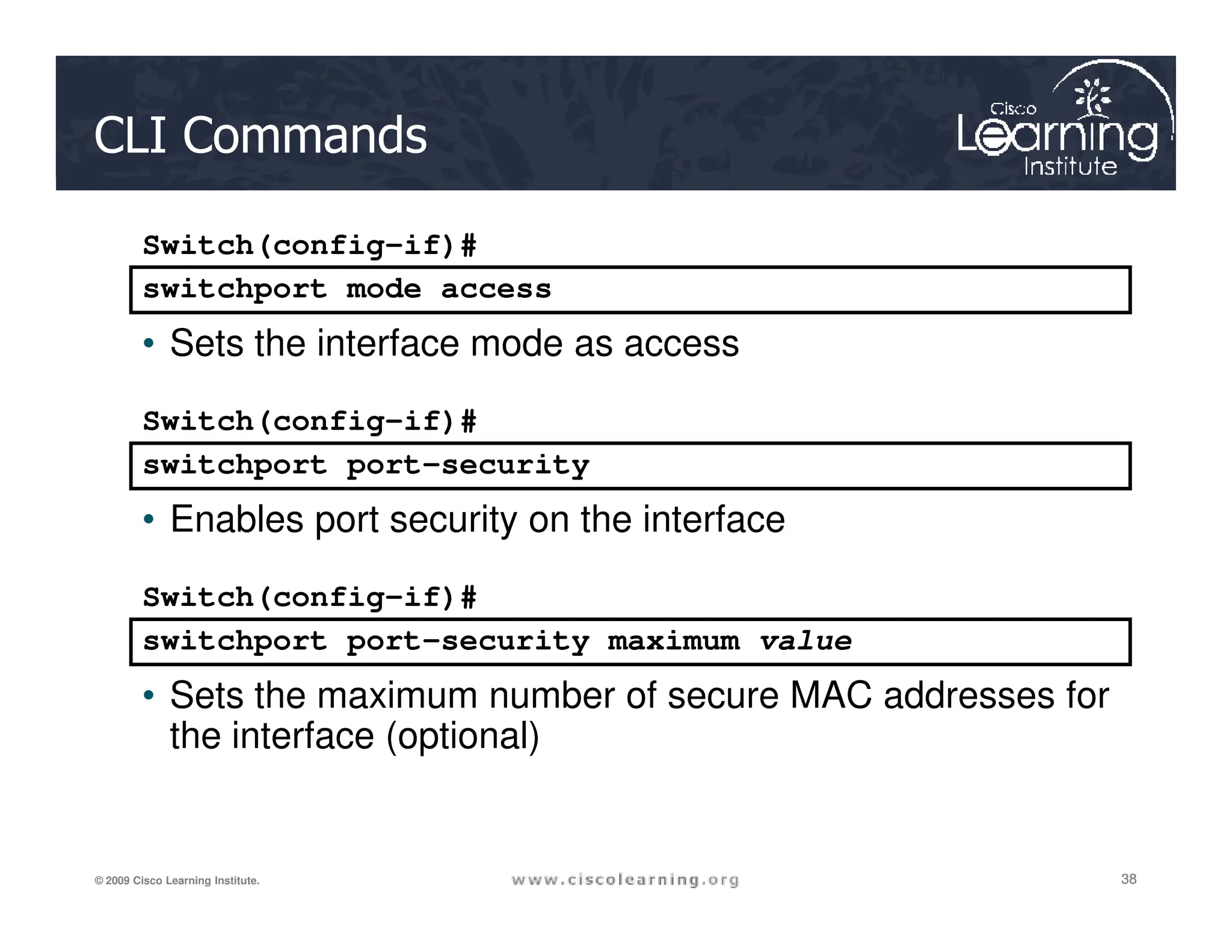
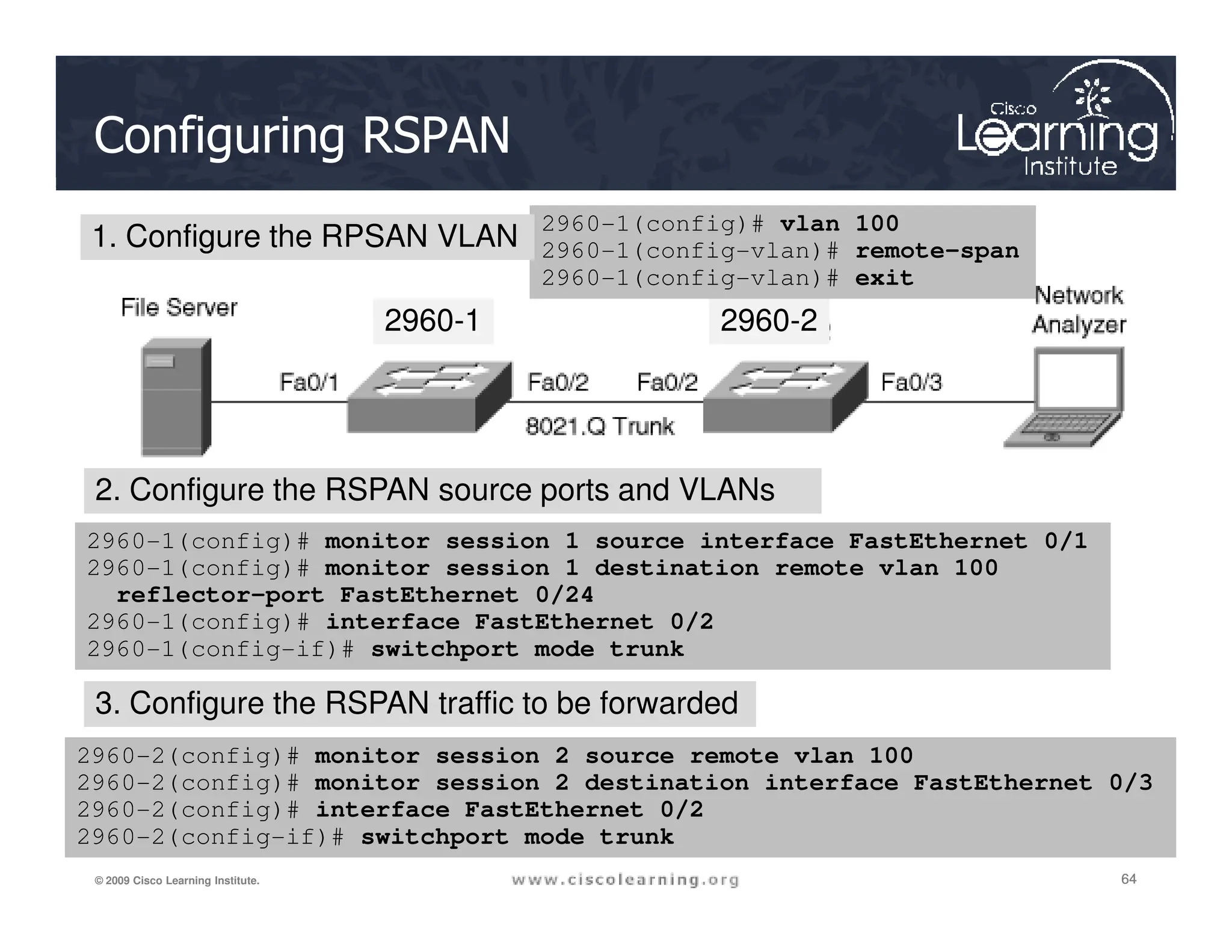
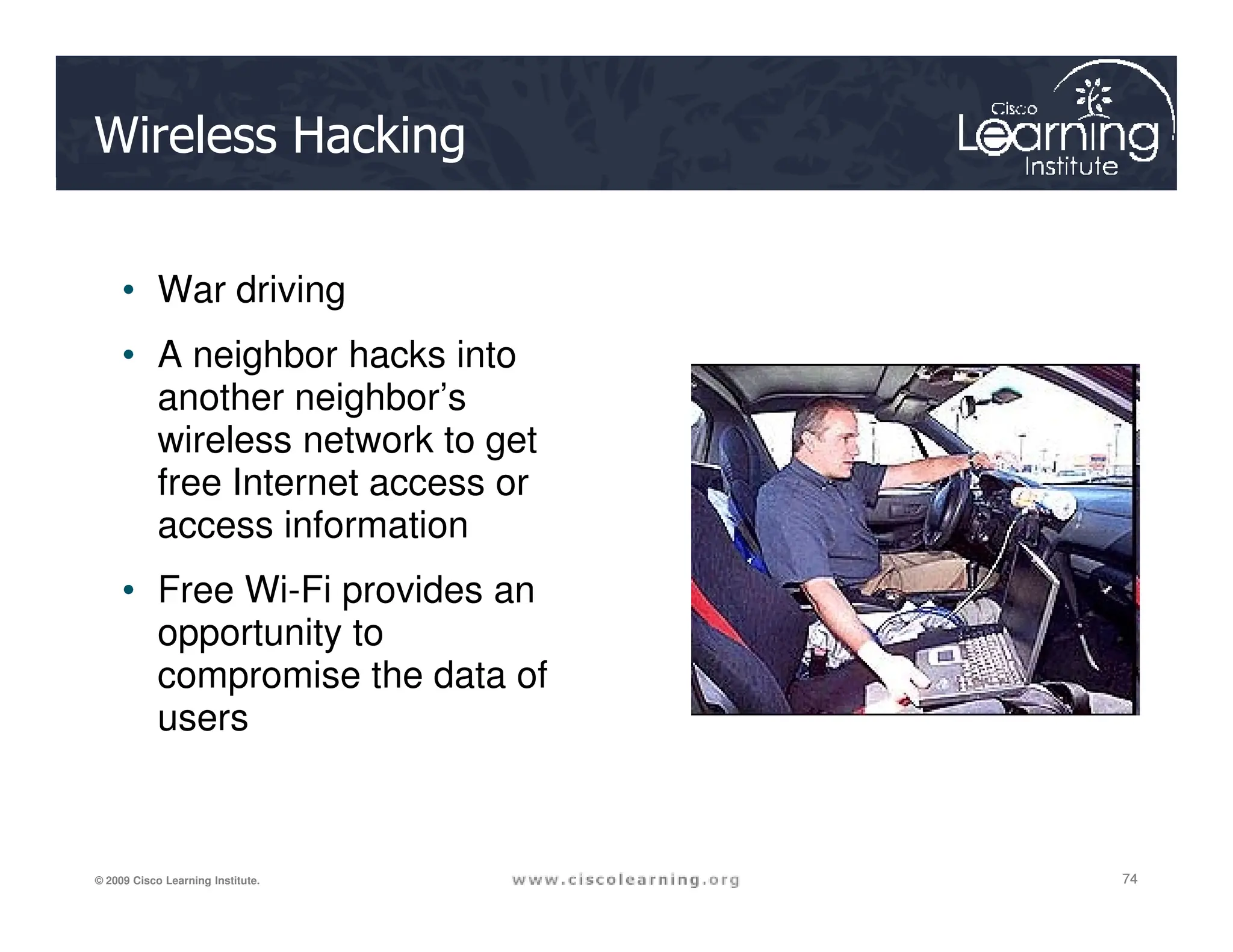
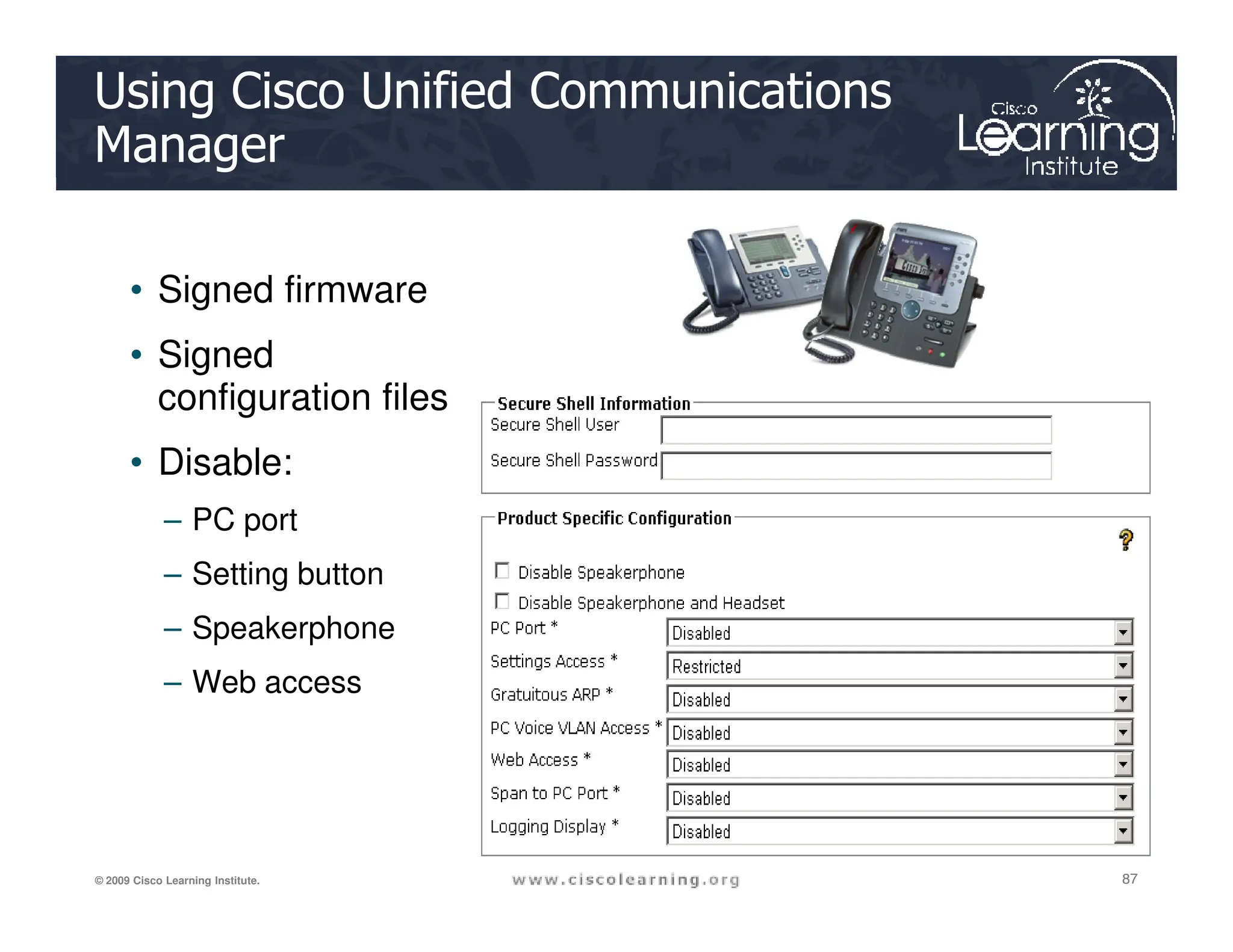
![CLI Commands
monitor session session_number source {interface
interface-id [, | -] [both | rx | tx]} | {vlan vlan-
id [, | -] [both | rx | tx]}| {remote vlan vlan-id}
Switch(config)#
60
60
60
© 2009 Cisco Learning Institute.
monitor session session_number destination
{interface interface-id [, | -] [encapsulation
replicate] [ingress {dot1q vlan vlan-id | isl |
untagged vlan vlan-id | vlan vlan-id}]} | {remote
vlan vlan-id}
Switch(config)#](https://image.slidesharecdn.com/ch6-240712063159-54c98ae1/75/Chapter-6-Securing-the-Local-Area-Network-pdf-60-2048.jpg)
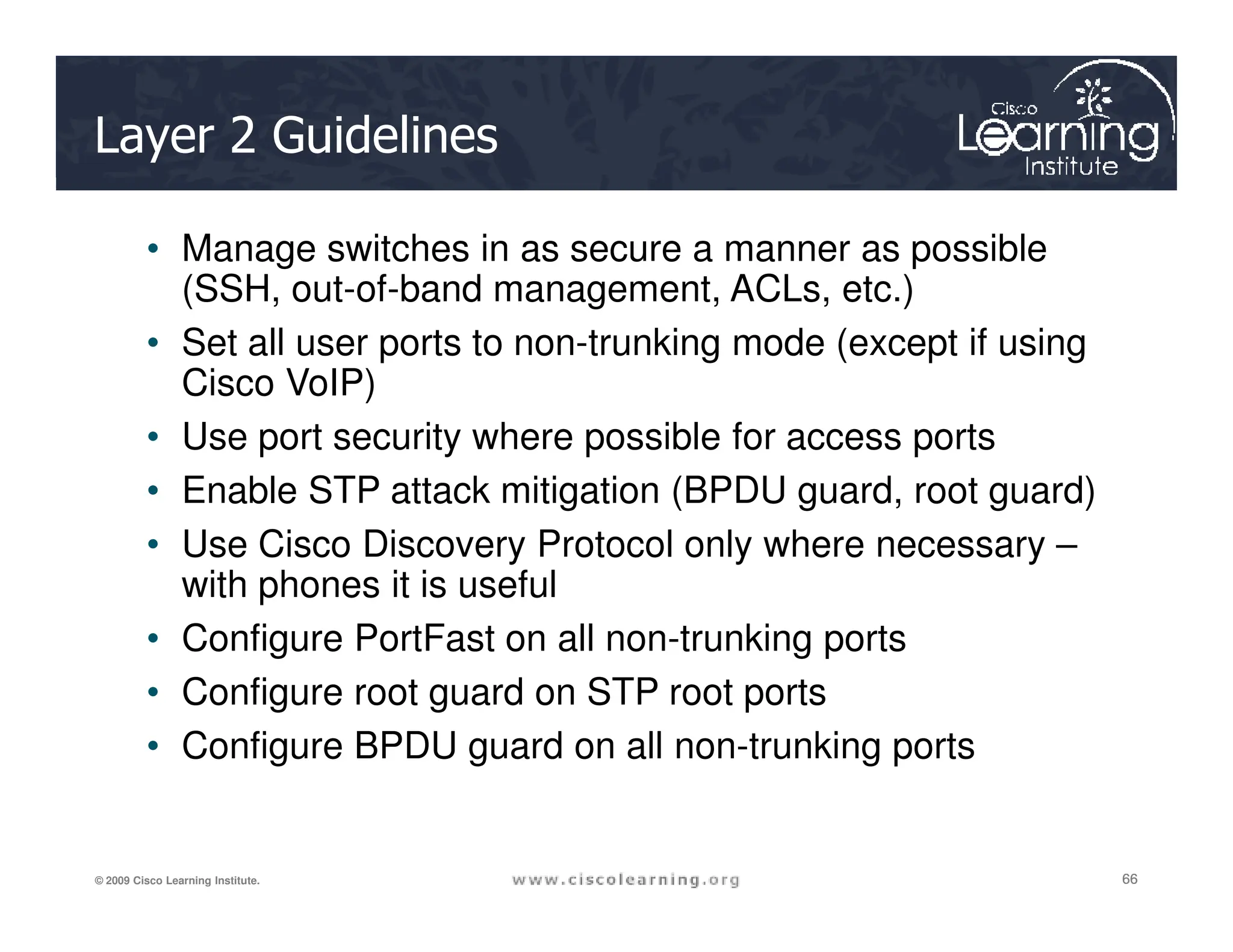
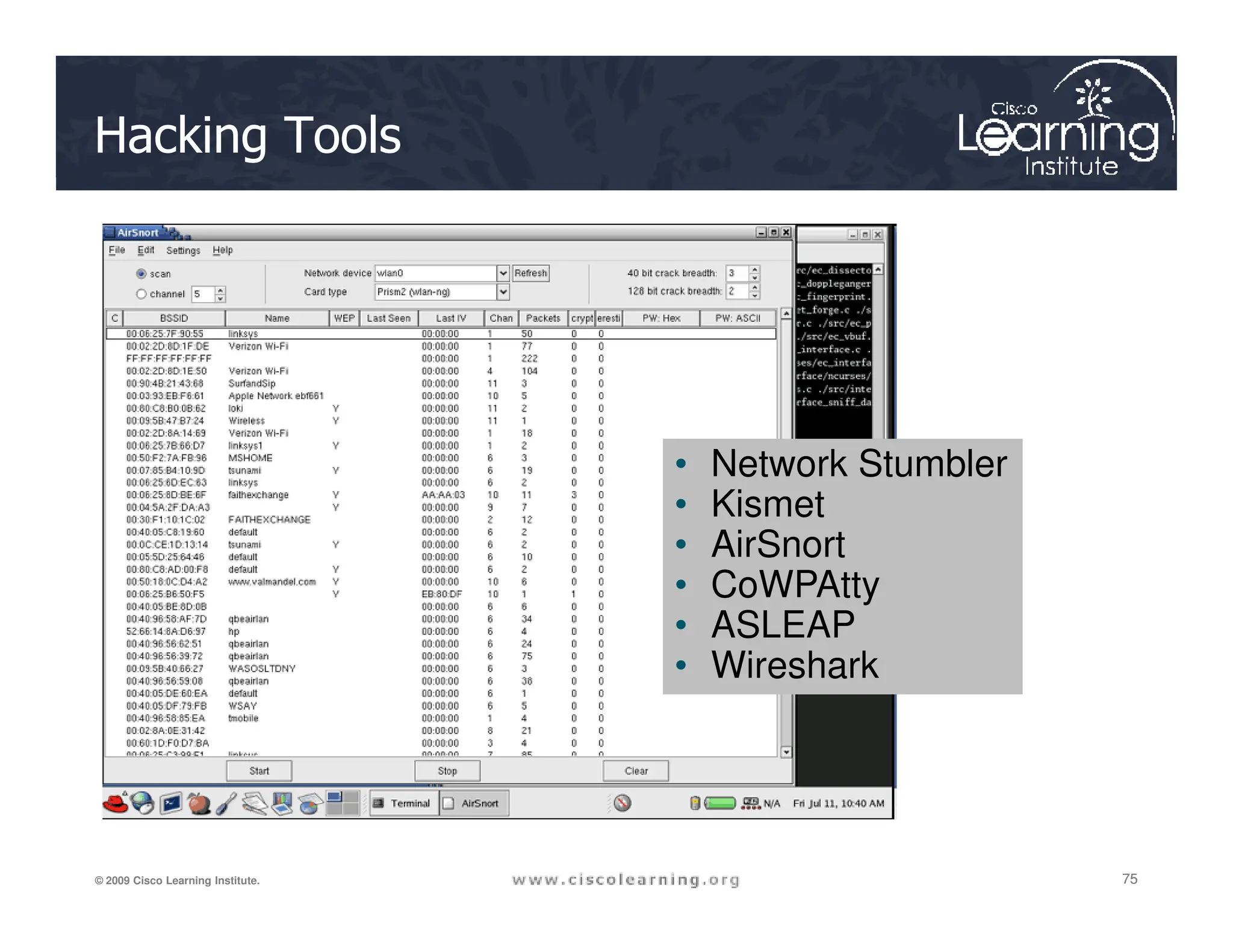
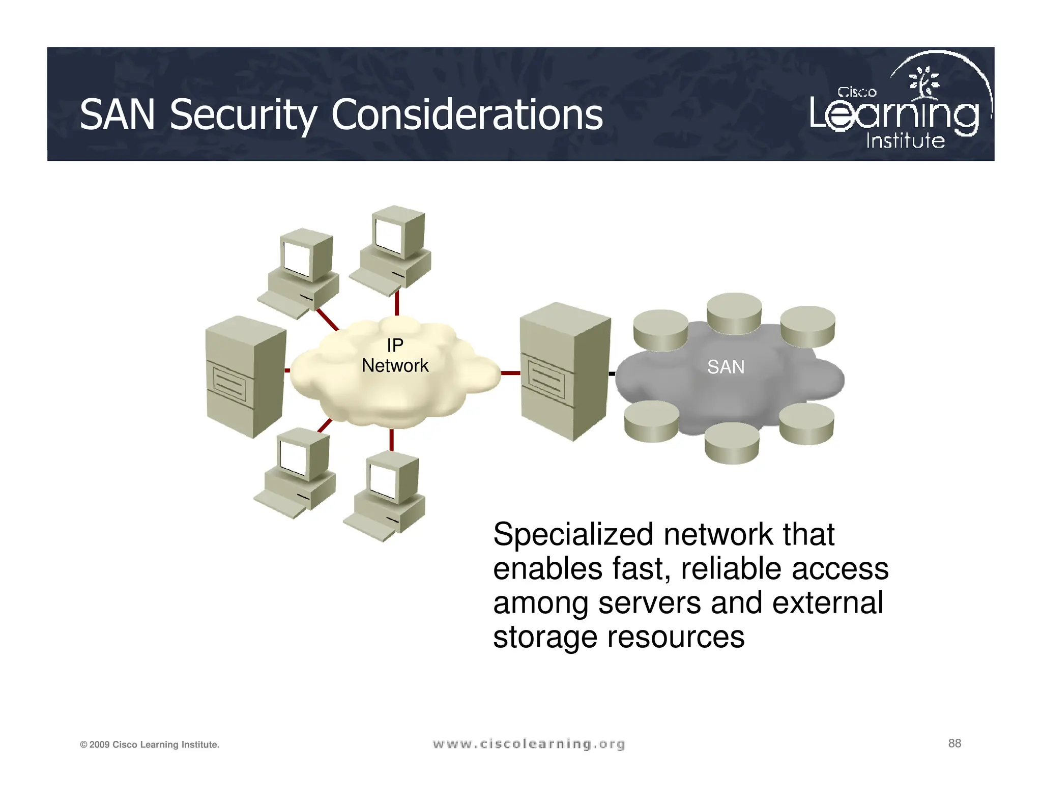
![Verifying RSPAN Configuration
2960-1 2960-2
65
65
65
© 2009 Cisco Learning Institute.
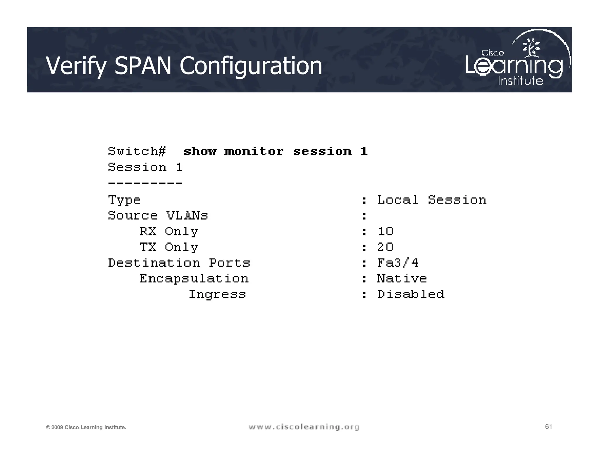
show monitor [session {session_number | all | local
| range list | remote} [detail]] [ | {begin | exclude
| include}expression]](https://image.slidesharecdn.com/ch6-240712063159-54c98ae1/75/Chapter-6-Securing-the-Local-Area-Network-pdf-65-2048.jpg)


![What is Technology for New IT Person [Basic]](https://cdn.slidesharecdn.com/ss_thumbnails/whatistechnology-240714164025-dd9a638c-thumbnail.jpg?width=640&height=640&fit=bounds)