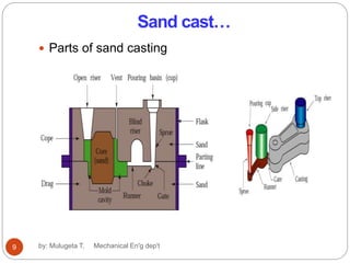
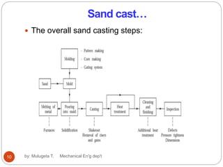
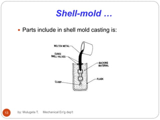
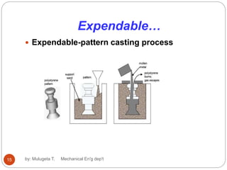
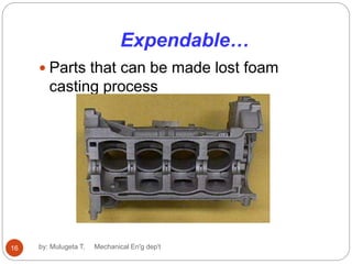
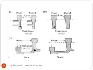
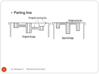
Production Engineering I
(MEng3161)
Chapter four
4. Fundamental of Casting
4.1 Introduction
 Casting is usually the first step of manufacturing.
In casting, a material in a liquid form is poured
in to a mold where it is allowed to solidify by
cooling (metals) or by reaction (plastics).
The mold cavity is carefully prepared so that it
has the desired shape and properties.
Castablity is a term, which reflects the ease
with which a metal can be poured in to a mold
to obtain a casting without defects and is
depends on pars design and material property.
1 by: Mulugeta T. Mechanical En'g dep't
Introduction
 A large number of metal components in designs
we use every day are made by casting. The
reasons for this include:
(a) Casting can produce very complex geometry
parts with internal cavities and hollow sections.
(b) It can be used to make small (few hundred
grams) to very large size parts (thousands of
kilograms)
(c) It is economical, with very little wastage: the
extra metal in each casting is re-melted and re-
used
(d) Cast metal is isotropic – it has the same
physical/mechanical properties along any
direction.2 by: Mulugeta T. Mechanical En'g dep't
Introduction
The material property for suitable castablity
depends on:
 Melting temperature
 Fluidity
 Latent heat of fusion
 Specific heat
 Thermal conductivity
 Resistance to hot cracking
 Shrinkage
 Metallurgical purity
3 by: Mulugeta T. Mechanical En'g dep't
Introduction
Quick route from raw material to finished product
 Preparation of mold (molding)
 Melt metals
 Pour / force liquid into hollow cavity (mold)
 Cool / Solidify
 Remove
 Finish
 The material to melted by using melting furnaces
such as blast furnaces, basic oxygen furnaces,
electric arc furnaces, industrial furnaces, etc
either by using internal or external heat energy.
4 by: Mulugeta T. Mechanical En'g dep't
Introduction
 In casting process, melting material and pouring
the melt liquid material in to the mold requires
high amount of energy and safety.
5 by: Mulugeta T. Mechanical En'g dep't
Introduction
There are different types of casting processes:
• Sand
• Shell
• Investment
• Die
• Plaster
• Ceramic
• Lost foam
• Pressure
• Vacuum
6 by: Mulugeta T. Mechanical En'g dep't
4.2 Sand cast
 Sand casting uses natural or synthetic sand
(lake sand) which is mostly a refractory material
called silica (SiO2).
 The sand grains must be small enough so that
it can be packed densely; however, the grains
must be large enough to allow gasses formed
during the metal pouring to escape through the
pores.
 Larger sized molds use green sand (mixture of
sand, clay and some water). Sand can be re-
used, and excess metal poured is cut-off and
re-used also.
7 by: Mulugeta T. Mechanical En'g dep't
Sand cast…
Typical sand molds have the following parts
 The mold is made of two parts, the top half is called
the cope, and bottom part is the drag.
 The liquid flows into the gap between the two parts,
called the mold cavity.
 The geometry of the cavity is created by the use of
a wooden shape, called the pattern. The shape of
the patterns is (almost) identical to the shape of the
part we need to make.
 A funnel shaped cavity; the top of the funnel is the
pouring cup; the pipe-shaped neck of the funnel is
the sprue – the liquid metal is poured into the
pouring cup, and flows down the sprue.
 The runners are the horizontal hollow channels
that connect the bottom of the sprue to the mould
cavity. The region where any runner joins with the
cavity is called the gate.
8
by: Mulugeta T. Mechanical En'g dep't
Sand cast…
 Parts of sand casting
9 by: Mulugeta T. Mechanical En'g dep't
Sand cast…
 The overall sand casting steps:
10 by: Mulugeta T. Mechanical En'g dep't
Sand cast…
 The mold cavity and core preparation includes
both shrinkage of metal during drying and
clearance for finishing.
 The finishing includes cutting of risers, sprue,
runner withdrawal of core holed parts and final
surface finishing the product.
11 by: Mulugeta T. Mechanical En'g dep't
4.3 Shell-mold casting
 Shell-mold is permanent mold casting yields
better surface quality and tolerances.
 The process is described as follows:
 - The 2-piece pattern is made of metal (e.g. aluminum or
steel), it is heated to between 175°C-370°C, and coated
with a lubricant, e.g. silicone spray.
 Each heated half-pattern is covered with a mixture of
sand and a thermoset resin/epoxy binder. The binder
glues a layer of sand to the pattern, forming a shell. The
process may be repeated to get a thicker shell.
 The assembly is baked to cure it
 The patterns are removed, and the two half-shells
joined together to form the mold; metal is poured
into the mold.
 When the metal solidifies, the shell is broken to get
the part.12 by: Mulugeta T. Mechanical En'g dep't
Shell-mold …
 Parts include in shell mold casting is:
13 by: Mulugeta T. Mechanical En'g dep't
4.4 Expendable-pattern
casting
 The pattern used in this process is made from
polystyrene (this is the light, white packaging
material).
 Polystyrene foam is 95% air bubbles, and the
material itself evaporates when the liquid metal is
poured on it.
 The pattern itself is made by molding – the
polystyrene beads and pentane are put inside an
aluminum mold, and heated; it expands to fill the
mold, and takes the shape of the cavity. The
pattern is removed, and used for the casting14 by: Mulugeta T. Mechanical En'g dep't
Expendable…
 Expendable-pattern casting process
15 by: Mulugeta T. Mechanical En'g dep't
Expendable…
by: Mulugeta T. Mechanical En'g dep't16
 Parts that can be made lost foam
casting process
4.5 Investment casting
 This is an old process, and has been used since
ancient times to make. It is also used to make
other small (few grams, though it can be used for
parts up to a few kilograms).
 An advantage of this process is that the wax can
carry very fine details – so the process not only
gives good dimensional tolerances, but also
excellent surface finish; in fact, almost any
surface texture as well as logos etc. can be
reproduced with very high level of detail.
 It is a process that performed a multiple patterns
are assembled to a central wax sprue.
17 by: Mulugeta T. Mechanical En'g dep't
Investment…
by: Mulugeta T. Mechanical En'g dep't18
 Multiple patterns are assembled to a single
central wax sprue
4.6 Vacuum casting
 This process is also called counter-gravity
casting. It is basically the same process as
investment casting, except for the step of filling
the mold.
 In this case, the material is sucked upwards into
the mould by a vacuum pump.
 One advantage of vacuum casting is that by
releasing the pressure a short time after the mold
is filled, we can release the un-solidified metal
back into the flask.
 Since most of the heat is conducted away from
the surface between the mold and the metal,
therefore the portion of the metal closest to the
mold surface always solidifies first; the solid front
travels inwards into the cavity19 by: Mulugeta T. Mechanical En'g dep't
Vacuum casting…
by: Mulugeta T. Mechanical En'g dep't20
 Vacuum casting process
4.7 Die casting
 Die casting is a very commonly used type of
permanent mold casting process.
 It is used for producing many components of
home appliances (e.g rice cookers, stoves, fans,
washing and drying machines, fridges), motors,
toys and hand-tools
 Die casting molds are expensive, and require
significant lead time to fabricate; they are
commonly called dies.
 There are two common types of die casting: hot-
and cold-chamber die casting.
21 by: Mulugeta T. Mechanical En'g dep't
Die casting
 Hot and cold die casting
22 by: Mulugeta T. Mechanical En'g dep't
4.8 Centrifugal casting
 Centrifugal casting uses a permanent mold that is
rotated about its axis at a speed between 300 to
3000 rpm as the molten metal is poured.
 Centrifugal forces cause the metal to be pushed
out towards the mold walls, where it solidifies
after cooling.
 Parts cast in this method have a fine grain
microstructure, which is resistant to atmospheric
corrosion; hence this method has been used to
manufacture pipes. Since metal is heavier than
impurities, most of the impurities and inclusions
are closer to the inner diameter and can be
machined away.
 surface finish along the inner diameter is also
23 by: Mulugeta T. Mechanical En'g dep't
Centrifugal…
 Centrifugal casting process of pipe production
24 by: Mulugeta T. Mechanical En'g dep't
4.9 Continuous casting
by: Mulugeta T. Mechanical En'g dep't25
 Continuous casting process includes metal
melting furnace, casting and drying, and finally
cutting of the product since it is continuous.
4.10 Casting design and quality
 Several factors affect the
quality/performance of cast parts,
therefore, the design of parts that must
be produced by casting, as well as the
design of casting molds and dies, must
account for these.
 You may think of these as design
guidelines, and their scientific basis lies
in the analysis, the strength and
behavior of materials.
26 by: Mulugeta T. Mechanical En'g dep't
4.10.1 Corners, angles and section
thickness
 Many casting processes lead to small surface
defects (e.g. blisters, scars, scabs or blows), or tiny
holes/impurities in the interior (e.g. inclusions, cold-
shuts, shrinkage cavities).
 These defects are a problem if the part with such a
defect is subject of varying loads during use.
 Under such conditions, it is likely that the defects act
like cracks, which propagate under repeated stress
causing fatigue failure.
 Another possibility is that internal holes act as stress
concentrators and reduce the actual strength of the
part below the expected strength of the design.
27 by: Mulugeta T. Mechanical En'g dep't
28 by: Mulugeta T. Mechanical En'g dep't
by: Mulugeta T. Mechanical En'g dep't29
4.10.2 Shrinkage
 As the casting cools, the metal shrinks.
 For common cast metals, a 1% shrinkage
allowance is designed in all linear dimensions
(namely, the design is scaled by approx. 1%).
 Since the solidification front, i.e. the surface at the
boundary of the solidified and the liquid metals,
travels from the surface of the mold to the interior
regions of the part, the design must ensure that
shrinkage does not cause cavities.
30 by: Mulugeta T. Mechanical En'g dep't
31 by: Mulugeta T. Mechanical En'g dep't
4.10.3 Parting line
 The parting line is the boundary where the cope, drag
and the part meet.
 If the surface of the cope and drag are planar, then
the parting line is the outline of the cross-section of
the part along that plane.
 You can easily see the parting line for many cast and
molded parts that you commonly use.
 It is conventional that the parting line should be
planar, if possible.
 A very small of metal will always “leak” outside the
mold between the cope and the drag in any casting.
This is called the “flash”.
 If the flash is along an external surface, it must be
machined away by some finishing operation
32 by: Mulugeta T. Mechanical En'g dep't
 Parting line
33 by: Mulugeta T. Mechanical En'g dep't
34 by: Mulugeta T. Mechanical En'g dep't

Chapter 4 casting by Mulugeta Tadesse

  • 1.
    Production Engineering I (MEng3161) Chapterfour 4. Fundamental of Casting 4.1 Introduction  Casting is usually the first step of manufacturing. In casting, a material in a liquid form is poured in to a mold where it is allowed to solidify by cooling (metals) or by reaction (plastics). The mold cavity is carefully prepared so that it has the desired shape and properties. Castablity is a term, which reflects the ease with which a metal can be poured in to a mold to obtain a casting without defects and is depends on pars design and material property. 1 by: Mulugeta T. Mechanical En'g dep't
  • 2.
    Introduction  A largenumber of metal components in designs we use every day are made by casting. The reasons for this include: (a) Casting can produce very complex geometry parts with internal cavities and hollow sections. (b) It can be used to make small (few hundred grams) to very large size parts (thousands of kilograms) (c) It is economical, with very little wastage: the extra metal in each casting is re-melted and re- used (d) Cast metal is isotropic – it has the same physical/mechanical properties along any direction.2 by: Mulugeta T. Mechanical En'g dep't
  • 3.
    Introduction The material propertyfor suitable castablity depends on:  Melting temperature  Fluidity  Latent heat of fusion  Specific heat  Thermal conductivity  Resistance to hot cracking  Shrinkage  Metallurgical purity 3 by: Mulugeta T. Mechanical En'g dep't
  • 4.
    Introduction Quick route fromraw material to finished product  Preparation of mold (molding)  Melt metals  Pour / force liquid into hollow cavity (mold)  Cool / Solidify  Remove  Finish  The material to melted by using melting furnaces such as blast furnaces, basic oxygen furnaces, electric arc furnaces, industrial furnaces, etc either by using internal or external heat energy. 4 by: Mulugeta T. Mechanical En'g dep't
  • 5.
    Introduction  In castingprocess, melting material and pouring the melt liquid material in to the mold requires high amount of energy and safety. 5 by: Mulugeta T. Mechanical En'g dep't
  • 6.
    Introduction There are differenttypes of casting processes: • Sand • Shell • Investment • Die • Plaster • Ceramic • Lost foam • Pressure • Vacuum 6 by: Mulugeta T. Mechanical En'g dep't
  • 7.
    4.2 Sand cast Sand casting uses natural or synthetic sand (lake sand) which is mostly a refractory material called silica (SiO2).  The sand grains must be small enough so that it can be packed densely; however, the grains must be large enough to allow gasses formed during the metal pouring to escape through the pores.  Larger sized molds use green sand (mixture of sand, clay and some water). Sand can be re- used, and excess metal poured is cut-off and re-used also. 7 by: Mulugeta T. Mechanical En'g dep't
  • 8.
    Sand cast… Typical sandmolds have the following parts  The mold is made of two parts, the top half is called the cope, and bottom part is the drag.  The liquid flows into the gap between the two parts, called the mold cavity.  The geometry of the cavity is created by the use of a wooden shape, called the pattern. The shape of the patterns is (almost) identical to the shape of the part we need to make.  A funnel shaped cavity; the top of the funnel is the pouring cup; the pipe-shaped neck of the funnel is the sprue – the liquid metal is poured into the pouring cup, and flows down the sprue.  The runners are the horizontal hollow channels that connect the bottom of the sprue to the mould cavity. The region where any runner joins with the cavity is called the gate. 8 by: Mulugeta T. Mechanical En'g dep't
  • 9.
    Sand cast…  Partsof sand casting 9 by: Mulugeta T. Mechanical En'g dep't
  • 10.
    Sand cast…  Theoverall sand casting steps: 10 by: Mulugeta T. Mechanical En'g dep't
  • 11.
    Sand cast…  Themold cavity and core preparation includes both shrinkage of metal during drying and clearance for finishing.  The finishing includes cutting of risers, sprue, runner withdrawal of core holed parts and final surface finishing the product. 11 by: Mulugeta T. Mechanical En'g dep't
  • 12.
    4.3 Shell-mold casting Shell-mold is permanent mold casting yields better surface quality and tolerances.  The process is described as follows:  - The 2-piece pattern is made of metal (e.g. aluminum or steel), it is heated to between 175°C-370°C, and coated with a lubricant, e.g. silicone spray.  Each heated half-pattern is covered with a mixture of sand and a thermoset resin/epoxy binder. The binder glues a layer of sand to the pattern, forming a shell. The process may be repeated to get a thicker shell.  The assembly is baked to cure it  The patterns are removed, and the two half-shells joined together to form the mold; metal is poured into the mold.  When the metal solidifies, the shell is broken to get the part.12 by: Mulugeta T. Mechanical En'g dep't
  • 13.
    Shell-mold …  Partsinclude in shell mold casting is: 13 by: Mulugeta T. Mechanical En'g dep't
  • 14.
    4.4 Expendable-pattern casting  Thepattern used in this process is made from polystyrene (this is the light, white packaging material).  Polystyrene foam is 95% air bubbles, and the material itself evaporates when the liquid metal is poured on it.  The pattern itself is made by molding – the polystyrene beads and pentane are put inside an aluminum mold, and heated; it expands to fill the mold, and takes the shape of the cavity. The pattern is removed, and used for the casting14 by: Mulugeta T. Mechanical En'g dep't
  • 15.
    Expendable…  Expendable-pattern castingprocess 15 by: Mulugeta T. Mechanical En'g dep't
  • 16.
    Expendable… by: Mulugeta T.Mechanical En'g dep't16  Parts that can be made lost foam casting process
  • 17.
    4.5 Investment casting This is an old process, and has been used since ancient times to make. It is also used to make other small (few grams, though it can be used for parts up to a few kilograms).  An advantage of this process is that the wax can carry very fine details – so the process not only gives good dimensional tolerances, but also excellent surface finish; in fact, almost any surface texture as well as logos etc. can be reproduced with very high level of detail.  It is a process that performed a multiple patterns are assembled to a central wax sprue. 17 by: Mulugeta T. Mechanical En'g dep't
  • 18.
    Investment… by: Mulugeta T.Mechanical En'g dep't18  Multiple patterns are assembled to a single central wax sprue
  • 19.
    4.6 Vacuum casting This process is also called counter-gravity casting. It is basically the same process as investment casting, except for the step of filling the mold.  In this case, the material is sucked upwards into the mould by a vacuum pump.  One advantage of vacuum casting is that by releasing the pressure a short time after the mold is filled, we can release the un-solidified metal back into the flask.  Since most of the heat is conducted away from the surface between the mold and the metal, therefore the portion of the metal closest to the mold surface always solidifies first; the solid front travels inwards into the cavity19 by: Mulugeta T. Mechanical En'g dep't
  • 20.
    Vacuum casting… by: MulugetaT. Mechanical En'g dep't20  Vacuum casting process
  • 21.
    4.7 Die casting Die casting is a very commonly used type of permanent mold casting process.  It is used for producing many components of home appliances (e.g rice cookers, stoves, fans, washing and drying machines, fridges), motors, toys and hand-tools  Die casting molds are expensive, and require significant lead time to fabricate; they are commonly called dies.  There are two common types of die casting: hot- and cold-chamber die casting. 21 by: Mulugeta T. Mechanical En'g dep't
  • 22.
    Die casting  Hotand cold die casting 22 by: Mulugeta T. Mechanical En'g dep't
  • 23.
    4.8 Centrifugal casting Centrifugal casting uses a permanent mold that is rotated about its axis at a speed between 300 to 3000 rpm as the molten metal is poured.  Centrifugal forces cause the metal to be pushed out towards the mold walls, where it solidifies after cooling.  Parts cast in this method have a fine grain microstructure, which is resistant to atmospheric corrosion; hence this method has been used to manufacture pipes. Since metal is heavier than impurities, most of the impurities and inclusions are closer to the inner diameter and can be machined away.  surface finish along the inner diameter is also 23 by: Mulugeta T. Mechanical En'g dep't
  • 24.
    Centrifugal…  Centrifugal castingprocess of pipe production 24 by: Mulugeta T. Mechanical En'g dep't
  • 25.
    4.9 Continuous casting by:Mulugeta T. Mechanical En'g dep't25  Continuous casting process includes metal melting furnace, casting and drying, and finally cutting of the product since it is continuous.
  • 26.
    4.10 Casting designand quality  Several factors affect the quality/performance of cast parts, therefore, the design of parts that must be produced by casting, as well as the design of casting molds and dies, must account for these.  You may think of these as design guidelines, and their scientific basis lies in the analysis, the strength and behavior of materials. 26 by: Mulugeta T. Mechanical En'g dep't
  • 27.
    4.10.1 Corners, anglesand section thickness  Many casting processes lead to small surface defects (e.g. blisters, scars, scabs or blows), or tiny holes/impurities in the interior (e.g. inclusions, cold- shuts, shrinkage cavities).  These defects are a problem if the part with such a defect is subject of varying loads during use.  Under such conditions, it is likely that the defects act like cracks, which propagate under repeated stress causing fatigue failure.  Another possibility is that internal holes act as stress concentrators and reduce the actual strength of the part below the expected strength of the design. 27 by: Mulugeta T. Mechanical En'g dep't
  • 28.
    28 by: MulugetaT. Mechanical En'g dep't
  • 29.
    by: Mulugeta T.Mechanical En'g dep't29
  • 30.
    4.10.2 Shrinkage  Asthe casting cools, the metal shrinks.  For common cast metals, a 1% shrinkage allowance is designed in all linear dimensions (namely, the design is scaled by approx. 1%).  Since the solidification front, i.e. the surface at the boundary of the solidified and the liquid metals, travels from the surface of the mold to the interior regions of the part, the design must ensure that shrinkage does not cause cavities. 30 by: Mulugeta T. Mechanical En'g dep't
  • 31.
    31 by: MulugetaT. Mechanical En'g dep't
  • 32.
    4.10.3 Parting line The parting line is the boundary where the cope, drag and the part meet.  If the surface of the cope and drag are planar, then the parting line is the outline of the cross-section of the part along that plane.  You can easily see the parting line for many cast and molded parts that you commonly use.  It is conventional that the parting line should be planar, if possible.  A very small of metal will always “leak” outside the mold between the cope and the drag in any casting. This is called the “flash”.  If the flash is along an external surface, it must be machined away by some finishing operation 32 by: Mulugeta T. Mechanical En'g dep't
  • 33.
     Parting line 33by: Mulugeta T. Mechanical En'g dep't
  • 34.
    34 by: MulugetaT. Mechanical En'g dep't