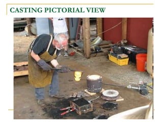
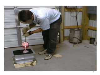
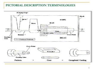
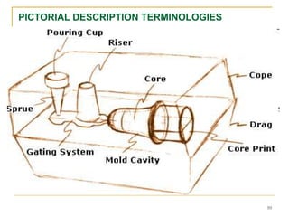
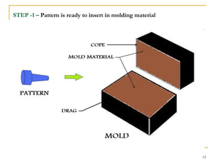
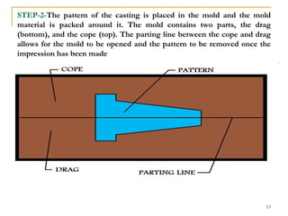
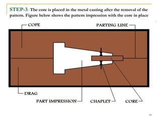
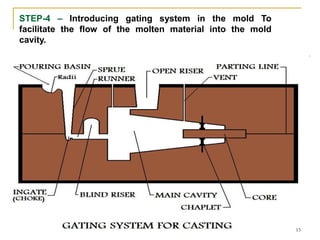
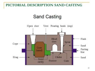
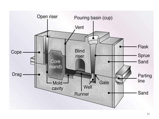
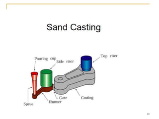
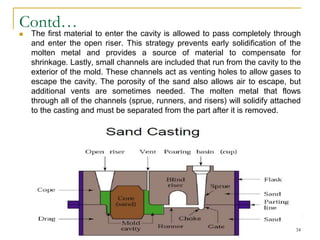
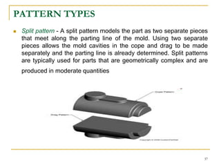
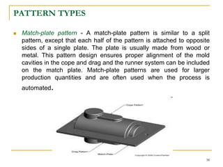
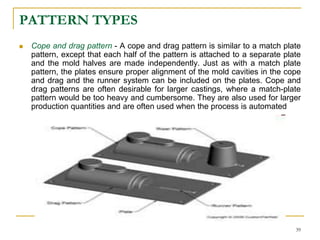
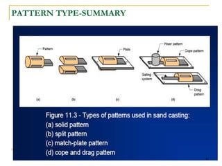
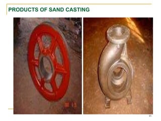
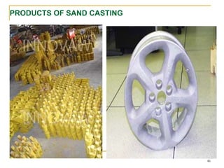
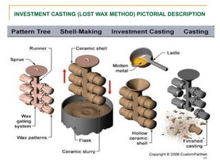
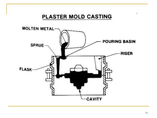
METAL CASTING PROCESS
MODULE -2A
By
DR. AQUEEL SHAH
Associate Professor IME
1
LEARNING OBJECTIVES
 Casting definition/understanding
 Casting terminologies/Pictorial description.
 Mold types
 Step by step mold making process
 Casting classification and types
 Study of casting types and application
 Casting defects
 Casting economies
REF-- Grover/ Kalpakjian & INTERNET
2
CASTING-DEFINITION
 In metalworking, casting involves pouring a liquid metal into a mold,
which contains a hollow cavity of the desired shape, and then is
allowed to solidify. The solidified part is also known as a casting,
which is ejected or broken out of the mold to complete the process.
Casting is most often used for making complex shapes that would
be difficult or uneconomical to make by other methods
 In choosing a casting technique we have to look at products like
what we want to produce, how the workload, whether the product is
a mass product, and consideration of the sale price. All that to
ensure the effectiveness of the foundry that we make
 APPLICATIONS:
 Engine blocks and manifolds, machine bases, gears, pulley
3
CASTING PICTORIAL VIEW
4
5
MAIN TERMINOLOGIES
 Pattern: An approximate duplicate of the final casting used to form the mold
cavity.
 Molding material: The material that is packed around the pattern and then
the pattern is removed to leave the cavity where the casting material will be
poured.
 Flask: The rigid wood or metal frame that holds the molding material.
 Cope The top half of the pattern, flask, mold, or core.
 Drag The bottom half of the pattern, flask, mold, or core.
 Core: An insert in the mold that produces internal features in the casting,
such as holes.
 Core print: The region added to the pattern, core, or mold used to locate
and support the core
6
Contd…
 Riser: An extra void in the mold that fills with molten material to
compensate for shrinkage during solidification.
 Gating system: The network of connected channels that deliver the
molten material to the mold cavities.
 Pouring cup or pouring basin: The part of the gating system
that receives the molten material from the pouring vessel.
 Sprue: The pouring cup attaches to the sprue, which is the
vertical part of the gating system. The other end of the sprue
attaches to the runners.
 Runners: The horizontal portion of the gating system that
connects the sprues to the gates.
 Gates: The controlled entrances from the runners into the mold
cavities
7
Contd…
 Vents: Additional channels that provide an escape for gases
generated during the pour.
 Parting line or parting surface: The interface between the cope
and drag halves of the mold, flask, or pattern.
 Draft: The taper on the casting or pattern that allow it to be
withdrawn from the mold
 Core box: The mold or die used to produce the core
8
PICTORIAL DESCRIPTION TERMINOLOGIES
9
PICTORIAL DESCRIPTION TERMINOLOGIES
10
STEP BY STEP MOLD MAKING PROCESS USING ALL
TERMINOLOGIES
11
STEP -1 – Pattern is ready to insert in molding material
12
STEP-2-The pattern of the casting is placed in the mold and the mold
material is packed around it. The mold contains two parts, the drag
(bottom), and the cope (top). The parting line between the cope and drag
allows for the mold to be opened and the pattern to be removed once the
impression has been made
13
STEP-3- The core is placed in the metal casting after the removal of the
pattern. Figure below shows the pattern impression with the core in place
14
STEP-4 – Introducing gating system in the mold To
facilitate the flow of the molten material into the mold
cavity.
15
CLASSIFICATION OF CASTING PROCESS
 CASTING process is generally classified according to mold material,
molding process and methods of feeding the mold with molten
metal.
 For the sake of convenience and understanding we would
categorize casting according to mould material i.e
 Consumable mold/expendable mold-mold is sacrificed to remove part
 Advantage: more complex shapes possible
 Disadvantage: production rates often limited by
 time to make mold rather than casting itself
 Permanent mold-mold is made of metal and can be used to make many
castings
 Advantage: higher production rates
 Disadvantage: geometries limited by need to open mold
 The casting is further divided with respect to pattern material
and molding process. The detail illustration is given on next
slide
16
IMPORTANT CONSIDERATION FOR MOLDS AND
PATTERNS
 EXPENDABLE MOLD CASTING
 Fe Materials always Cast in Expendable/Disposable mold
 Permanent mold casting
 Non Fe Materials always cast in Permanent mold
 PATTERN TYPES:
 CONSUMABLE/EXPENDABLE PATTERN – FULL MODE PROCESS
 PERMANENT PATTERN OR REMOVABLE PATTERN
17
18
CASTING PROCESS TYPE-1
CONSUMABLE/EXPENDABLE MOLD
19
SAND CASTING
 Sand casting, also known as sand molded casting, is a metal
casting process characterized by using sand as the mold
material.
 It is relatively cheap and sufficiently refractory even for steel
foundry use. A suitable bonding agent (usually clay) is mixed or
occurs with the sand. The mixture is moistened with water to
develop strength and plasticity of the clay and to make the
aggregate suitable for molding. The term "sand casting" can also
refer to a casting produced via the sand casting process. Sand
castings are produced in specialized factories called foundries.
 Over 70% of all metal castings are produced via a sand casting
process
20
THE BASIC STEPS
 There are six steps in this process:
 Place a pattern in sand to create a mold.
 Incorporate the pattern and sand in a gating system.
 Remove the pattern.
 Fill the mold cavity with molten metal.
 Allow the metal to cool.
 Break away the sand mold and remove the casting.
21
PICTORIAL DESCRIPTION SAND CASTING
22
23
24
25
COMPONENTS OF SAND CASTING
 MOLD
 SAND – require to make mold , types of sand , properties and
test
 Gating system
 Patterns
 Pattern types, pattern allownaces
 MOLDING BOXES/FLASKS
 Chills
 Cores
26
MOLD
 In sand casting, the primary piece of equipment is the mold,
which contains several components. The mold is divided into two
halves i.e. the cope (upper half) and the drag (bottom half), which
meet along a parting line. Both mold halves are contained inside
a box, called a flask, which itself is divided along this parting line.
The mold cavity is formed by packing sand around the pattern in
each half of the flask. The sand can be packed by hand, but
machines that use pressure or impact ensure even packing of
the sand and require far less time, thus increasing the production
rate. After the sand has been packed and the pattern is removed,
a cavity will remain that forms the external shape of the casting.
Some internal surfaces of the casting may be formed by cores
27
DESIRABLE MOLD PROPERTIES AND
CHARACTERISTICS
 STRENGTH - to maintain shape and resist erosion
 PERMEABILITY - to allow hot air and gases to pass through voids in sand
 THERMAL STABILITY - to resist cracking on contact with molten metal
 COLLAPSIBILITY - ability to give way and allow casting to shrink without
cracking the casting
 REUSABILITY - can sand from broken mold be reused to make other
molds?
28
SAND
 The sand that is used to create the molds is typically silica sand
(SiO2) that is mixed with a type of binder to help maintain the shape
of the mold cavity. Using sand as the mold material offers several
benefits to the casting process. Sand is very inexpensive and is
resistant to high temperatures, allowing many metals to be cast that
have high melting temperatures. There are different preparations of
the sand for the mold, which characterize the following four unique
types of sand molds
 Greensand mold - Greensand molds use a mixture of sand, water, and
a clay or binder. Typical composition of the mixture is 90% sand, 3%
water, and 7% clay or binder. Greensand molds are the least expensive
and most widely used.
29
Contd…
 Skin-dried mold - A skin-dried mold begins like a greensand
mold, but additional bonding materials are added and the cavity
surface is dried by a torch or heating lamp to increase mold
strength. Doing so also improves the dimensional accuracy and
surface finish, but will lower the collapsibility. Dry skin molds are
more expensive and require more time, thus lowering the
production rate.
 Dry sand mold - In a dry sand mold, sometimes called a cold
box mold, the sand is mixed only with an organic binder. The
mold is strengthened by baking it in an oven. The resulting mold
has high dimensional accuracy, but is expensive and results in a
lower production rate.
 No-bake mold - The sand in a no-bake mold is mixed with a
liquid resin and hardens at room temperature
30
PROPERTIES OF SAND
 Permeability-This allows the gases and steam to escape from the
mold during casting.
 Strength-Have the ability to support its own weight when stripped
from the pattern, and also withstand pressure of molten metal when
the mold is cast
 Refractoriness- This provide resistance to high temperatures
 Grain size- Fine round grains can be closely packed and provide
smooth mold surface.
 Collapsibility- good collapsibility will prevent casting defects like
hot tearing and cracking (we will discuss these defects in detail in
later section of lecture).
31
TESTING OF SAND
 Mold and core hardness test
 Fines test
 Moisture content test
 Clay content test
 Permeability test
 Strength test
32
GATING SYSTEM
 In addition to the external and internal features of the casting, other
features must be incorporated into the mold to accommodate the
flow of molten metal. The molten metal is poured into a pouring
basin, which is a large depression in the top of the sand mold. The
molten metal funnels out of the bottom of this basin and down the
main channel, called the sprue. The sprue then connects to a series
of channels, called runners, which carries the molten metal into the
cavity. At the end of each runner, the molten metal enters the cavity
through a gate which controls the flow rate and minimizes
turbulence. Often connected to the runner system are risers. Risers
are chambers that fill with molten metal, providing an additional
source of metal during solidification. When the casting cools, the
molten metal will shrink and additional material is needed. A similar
feature that aids in reducing shrinkage is an open riser.
33
Contd…
 The first material to enter the cavity is allowed to pass completely through
and enter the open riser. This strategy prevents early solidification of the
molten metal and provides a source of material to compensate for
shrinkage. Lastly, small channels are included that run from the cavity to the
exterior of the mold. These channels act as venting holes to allow gases to
escape the cavity. The porosity of the sand also allows air to escape, but
additional vents are sometimes needed. The molten metal that flows
through all of the channels (sprue, runners, and risers) will solidify attached
to the casting and must be separated from the part after it is removed.
34
PATTERN
 From the design, provided by an engineer or designer, a skilled pattern
maker builds a pattern of the object to be produced, using wood,
metal, or a plastic such as expanded polystyrene.
 The pattern is actually made to be slightly larger than the part because
the casting will shrink inside the mold cavity. The difference known as
contraction allowance.
 Pattern-makers are able to produce suitable patterns using 'Contraction
rules' (these are sometimes called "shrink allowance rulers" where the
ruled markings are deliberately made to a larger spacing according to
the percentage of extra length needed). Different scales rules are used
for different metals because each metal and alloy contracts by an
amount distinct from all others. Patterns also have core prints that
create registers within the molds into which are placed sand 'cores.
Such cores, sometimes reinforced by wires, are used to create under
cut profiles and cavities which cannot be molded with the cope and
drag, such as the interior passages of valves or cooling passages in
engine blocks
35
PATTERN TYPES
 Solid pattern - A solid pattern is a model of the part as a single
piece. It is the easiest to fabricate, but can cause some difficulties in
making the mold. The parting line and runner system must be
determined separately. Solid patterns are typically used for
geometrically simple parts that are produced in low quantities
36
PATTERN TYPES
 Split pattern - A split pattern models the part as two separate pieces
that meet along the parting line of the mold. Using two separate
pieces allows the mold cavities in the cope and drag to be made
separately and the parting line is already determined. Split patterns
are typically used for parts that are geometrically complex and are
produced in moderate quantities
37
PATTERN TYPES
 Match-plate pattern - A match-plate pattern is similar to a split
pattern, except that each half of the pattern is attached to opposite
sides of a single plate. The plate is usually made from wood or
metal. This pattern design ensures proper alignment of the mold
cavities in the cope and drag and the runner system can be included
on the match plate. Match-plate patterns are used for larger
production quantities and are often used when the process is
automated.
38
PATTERN TYPES
 Cope and drag pattern - A cope and drag pattern is similar to a match plate
pattern, except that each half of the pattern is attached to a separate plate
and the mold halves are made independently. Just as with a match plate
pattern, the plates ensure proper alignment of the mold cavities in the cope
and drag and the runner system can be included on the plates. Cope and
drag patterns are often desirable for larger castings, where a match-plate
pattern would be too heavy and cumbersome. They are also used for larger
production quantities and are often used when the process is automated
39
PATTERN TYPE-SUMMARY
40
PATTERN ALLOWANCES
 Shrinkage-Solid shrinkage is the reduction in volume caused when
metal loses temperature in solid state. The shrinkage allowance was
provided to take care of this reduction e.g. Aluminum permissible
shrinkage allowance is 0.013 mm, but 0.01 mm shrinkage allowance
was provided in the pattern
 Draft-At the time of withdrawing the pattern from the sand mold, the
vertical faces of the pattern are in continual contact with the sand,
which may damage the mold cavity. To reduce the chances of this
happening the vertical faces of the pattern are always tapered from
the parting line. This provision is called draft allowance. Suggested
draft values for wood pattern are outer 0.25 to 3.0 degree. The
above values were provided for provided for wood pattern
41
Contd…
 Finishing-Extra material is to be provided which is to be
subsequently removed by machining or cleaning process.
Suggested machining allowance or pattern for non ferrous metal up
to 3 mm but 2mm allowance was provided on pattern
 Distortion-A metal when it has just solidified is very weak and
therefore is likely to be distortion prone. This is particularly so far
weaker sections such as long flat portions, V section or in a
complicated casting which may have thin and long sections
 Shake-Before withdrawal from the sand mold, the pattern is wraped
all around the vertical faces to enlarge the mold cavity slightly which
facilitates its removal. Since it enlarges the final casting made, it is
desirable that the original pattern dimensions should be reduced to
account for this increase
42
CORES
 To produce cavities within the casting (for example as for liquid
cooling in engine blocks and cylinder heads negative forms are used
to produce cores. Usually sand-molded, cores are inserted into the
casting box after removal of the pattern
 Each core is positioned in the mold before the molten metal is
poured. In order to keep each core in place, the pattern has
recesses called core prints where the core can be anchored in
place. However, the core may still shift due to buoyancy in the
molten metal. Further support is provided to the cores by
chaplets. These are small metal pieces that are fastened
between the core and the cavity surface. Chaplets must be made
of a metal with a higher melting temperature than that of the metal
being cast in order to maintain their structure. After solidification, the
chaplets will have been cast inside the casting and the excess
material of the chaplets that protrudes must be cut off. .
43
PICTORIAL DESCRIPTION OF CORE AND CHAPLETS
44
PRODUCTS OF SAND CASTING
45
PRODUCTS OF SAND CASTING
46
FURNACES FOR CASTING OPERATIONS-(PICS ON
NEXT SLIDES)
 Furnaces most commonly used in foundries:
 Cupolas- vertical furnace largest used only for cast irons, and although
other furnaces are also used, largest tonnage of cast iron is melted in
cupolas
 Direct fuel-fired furnaces-Small open-hearth in which charge is heated
by natural gas fuel burners located on side of furnace generally use for
non ferrous metals.
 Crucible furnaces- indirect fuel furnace where metal is melted without
direct contact with flame , normally use for non ferrous metals.
 Electric-arc furnaces- electric arc is use to melt metal , primarily for steel
 Induction furnaces- induced AC current in coil is used to melt metal and
resulting EMF cause mixing action in liquid metal. High quality is
obtained and applicable for both ferrous and non ferrous metals.
47
CRUCIBLE FURNACE PICTORIAL DESCRIPTION
48
ELECTRIC ARC FURNACE PICTORIAL DESCRIPTION
49
INDUCTION FURNACE PICTORIAL DESCRIPTION
50
ADVANTAGES OF SAND CASTING
 Can produce very large parts
 Can form complex shapes
 Many material options
 Low tooling and equipment cost
 Scrap can be recycled-
 Short lead time possible
51
DISADVANTAGES OF SAND CASTING
 Poor material strength-
 High porosity possible
 Poor surface finish and tolerance
 Secondary machining often required
 Low production rate
 High labor cost
52
SHELL MOLD CASTING
 Shell mold casting is a metal casting process similar to sand casting,
in that molten metal is poured into an expendable mold. However, in
shell mold casting, the mold is a thin-walled shell created from
applying a sand-resin mixture around a pattern. The pattern, a metal
piece in the shape of the desired part, is reused to form multiple
shell molds. A reusable pattern allows for higher production rates,
while the disposable molds enable complex geometries to be cast.
Shell mold casting requires the use of a metal pattern, oven, sand-
resin mixture, dump box, and molten metal.
 Shell mold casting allows the use of both ferrous and non-ferrous
metals, most commonly using cast iron, carbon steel, alloy steel,
stainless steel, aluminum alloys, and copper alloys. Typical parts
are small-to-medium in size and require high accuracy, such as gear
housings, cylinder heads, connecting rods, and lever arms
53
STEPS IN SHELL MOLD CASTING
 Pattern creation - A two-piece metal pattern is created in the shape of
the desired part, typically from iron or steel. Other materials are
sometimes used, such as aluminum for low volume production or
graphite for casting reactive materials.
 Mold creation - First, each pattern half is heated to 175-370°C (350-
700°F) and coated with a lubricant to facilitate removal. Next, the
heated pattern is clamped to a dump box, which contains a mixture of
sand and a resin binder. The dump box is inverted, allowing this sand-
resin mixture to coat the pattern. The heated pattern partially cures the
mixture, which now forms a shell around the pattern. Each pattern half
and surrounding shell is cured to completion in an oven and then the
shell is ejected from the pattern.
 Mold assembly - The two shell halves are joined together and securely
clamped to form the complete shell mold. If any cores are required, they
are inserted prior to closing the mold. The shell mold is then placed into
a flask and supported by a backing material.
54
Contd..
 Pouring - The mold is securely clamped together while the molten
metal is poured from a ladle into the gating system and fills the mold
cavity.
 Cooling - After the mold has been filled, the molten metal is allowed
to cool and solidify into the shape of the final casting.
 Casting removal - After the molten metal has cooled, the mold can
be broken and the casting removed. Trimming and cleaning
processes are required to remove any excess metal from the feed
system and any sand from the mold
55
56
SHELL-MOLD CASTING-PICTORIAL DESCRIPTION
Common methods of making shell molds.
(a) Pattern rotated and clamped
(b) Pattern and dump box rotated
(c) Pattern dump box in position for the
investment
(d) Pattern and shell removed from dump box
57
PICTORIAL DESCRIPTION SHELL MOLD CASTING
58
PICTORIAL DESCRIPTION SHELL MOLD CASTING
59
ADVANTAGES SHELL MOLD CASTING
 Can form complex shapes and fine details
 Very good surface finish
 High production rate
 Low labor cost
 Little scrap generated
60
EXPENDABLE POLYSTYRENE CASTING/LOST FOAM
PROCESS
 In the expanded polystyrene casting process a sand mold is packed
around a polystyrene pattern representing the metal casting to be
manufactured. The pattern is not removed, and the molten metal is
poured into the pattern which is vaporized from the heat of the
metal. The liquid metal takes the place of the vaporized polystyrene
and the casting solidifies in the sand mold
 In metal casting industry this process is known as the lost-
foam process, evaporative pattern casting, or the full mold
process. A large variety of castings of different sizes and materials
can be manufactured using this technique. Parts produced in
manufacturing industry using this process include crankshafts,
cylinder heads, machine bases, manifolds, and engine blocks
61
EXPENDABLE POLYSTYRENE CASTING-PICTORIAL
DESCRIPTION
62
EXPENDABLE POLYSTYRENE CASTING-
PICTORIAL DESCRIPTION
63
CONSIDERATIONS FOR EXPENDABLE POLYSTRENE
CASTING/ LOST FOAM PROCESS
 If a core is need it is incorporated within the pattern. Therefore
placing and securing a core in the mold cavity before the pouring of
the casting is not a step in this manufacturing process.
 Flasks for this process are simple and not expensive. Also the
manufacturing process itself is easy, since there is no parting line or
removal of the pattern needed.
 In manufacturing industry patterns for expanded polystyrene casting
will always include the full gating system.
64
Contd…
 Very complex casting geometry can be produced using this process.
 It can be very efficient in the production of metal castings for large
industrial runs. The main cost is to create the die to produce the foam
polystyrene patterns. Once that is overcome the process itself is very
inexpensive.
 This manufacturing process can be easily automate
65
ADVANTAGES/DISADVATAGES OF LOST FOAM
CASTING PROCESS
66
INVESTMENT CASTING (LOST WAX METHOD)
 Investment casting is a manufacturing process in which a wax
pattern is coated with a refractory ceramic material. Once the
ceramic material is hardened its internal geometry takes the shape
of the casting. The wax is melted out and molten metal is poured
into the cavity where the wax pattern was. The metal solidifies within
the ceramic mold and then the metal casting is broken out. This
manufacturing technique is also known as the lost wax process.
Investment casting was developed over 5500 years ago and can
trace its roots back to both ancient Egypt and China. Parts
manufactured in industry by this process include dental fixtures,
gears, cams, ratchets, jewelry, turbine blades, machinery
components and other parts of complex geometry
 It is precision casting method as it is capable to produce casting of
high accuracy and intricate details
67
INVESTMENT CASTING (LOST WAX METHOD) PICTORIAL DESCRIPTION
68
INVESTMENT CASTING (LOST WAX METHOD) PICTORIAL DESCRIPTION
69
INVESTMENT CASTING ADVANTAGES/DISADVANTAGES
APPLICATION
 ADVANTAGES:
 Can form complex shapes and fine details
 Many material options
 High strength parts
 Very good surface finish and accuracy
 Little need for secondary machining
 DISADVANTAGES
 Time-consuming process
 High labor cost
 High tooling cost
Application: Turbine blades, armament parts, pipe fittings, lock
parts, hand tools, jewelry
70
PLASTER MOLD CASTING
 Plaster mold casting is a metalworking casting process similar to
sand casting except the molding material is plaster of paris instead
of sand. Like sand casting, plaster mold casting is an expendable
mold processes, however it can only be used with non-ferrous
materials. It is used for castings as small as 30 g to as large as
45 kg.
 Parts typically made by plaster casting are lock components, gears,
valves, tooling, and ornament
 Low temperature melting materials such as aluminum, copper,
magnesium and zinc can be cast using this process. This process is
used to make quick prototype parts as well as limited production
parts
71
72
PICTORIAL DESCRIPTION PLASTER MOLD CASTING
73
PICTORIAL DESCRIPTION PLASTER MOLD CASTING
74
ADVANTAGES AND DISADVANTAGES OF PLASTER
MOLD CASTING
 Plaster mold casting is used to when an excellent surface finish and
good dimensional accuracy is required. Because the plaster has a low
thermal conductivity and heat capacity the metal cools more slowly than
in a sand mold, which allows the metal to fill thin cross-sections; the
minimum possible cross-section is 0.6 mm (0.024 in). This results in a
near net shape casting, which can be a cost advantage on complex
parts. It also produces minimal scrap material.
 The major disadvantage of the process is that it can only be used with
lower melting temperature non-ferrous materials, such as aluminum,
copper, magnesium, and zinc. The most commonly used materials are
aluminum and copper. The maximum working temperature of plaster is
1,200 °F (649 °C), so higher melting temperature materials would melt
the plaster mold. Also, the sulfur in the gypsum reacts with iron, making
it unsuitable for casting ferrous materials.
 Another disadvantage is that its long cooling times restrict production
volume
75
CERAMIC MOLD CASTING
 Similar to plaster mold casting, the pattern used in ceramic mold
casting is made of plaster, plastic, wood, metal or rubber. A
slurry of ceramic is poured over the pattern. It hardens rapidly to the
consistency of rubber. This can be peeled of the pattern,
reassembled as a mold. It is then baked in a furnace at about 1000
°C yielding a ceramic mold, capable of high temperature pours.
Additionally, the pour can take place while the mold is until hot.
 This process is expensive, but can eliminate secondary machining
operations. Typical parts made from this process include impellers
made from stainless steel or bronze, complex cutting tools, plastic
mold tooling
76
STEPS INVOLVED IN CERAMIC MOLD CASTING
 The ceramic slurry is poured over the pattern.
 It hardens rapidly to the consistency of rubber.
 It is then peeled from the pattern and reassembled as a mold.
 The volatiles are removed using a flame torch or in a low
temperature oven.
 It is then baked in a furnace at about 1000 degrees Celsius or 1832
degrees F yielding a ceramic mold.
 The mold is now capable of high temperature pours.
77
PICTORIAL DESCRIPTION CERAMIC MOLD CASTING
78
Contd…
 The process is expensive but can produce castings with fine detail,
smooth surfaces and a high degree of dimensional accuracy.
THANK YOU
79

2 CASTING SAND FIRST LECTURE.ppt

  • 1.
    METAL CASTING PROCESS MODULE-2A By DR. AQUEEL SHAH Associate Professor IME 1
  • 2.
    LEARNING OBJECTIVES  Castingdefinition/understanding  Casting terminologies/Pictorial description.  Mold types  Step by step mold making process  Casting classification and types  Study of casting types and application  Casting defects  Casting economies REF-- Grover/ Kalpakjian & INTERNET 2
  • 3.
    CASTING-DEFINITION  In metalworking,casting involves pouring a liquid metal into a mold, which contains a hollow cavity of the desired shape, and then is allowed to solidify. The solidified part is also known as a casting, which is ejected or broken out of the mold to complete the process. Casting is most often used for making complex shapes that would be difficult or uneconomical to make by other methods  In choosing a casting technique we have to look at products like what we want to produce, how the workload, whether the product is a mass product, and consideration of the sale price. All that to ensure the effectiveness of the foundry that we make  APPLICATIONS:  Engine blocks and manifolds, machine bases, gears, pulley 3
  • 4.
  • 5.
  • 6.
    MAIN TERMINOLOGIES  Pattern:An approximate duplicate of the final casting used to form the mold cavity.  Molding material: The material that is packed around the pattern and then the pattern is removed to leave the cavity where the casting material will be poured.  Flask: The rigid wood or metal frame that holds the molding material.  Cope The top half of the pattern, flask, mold, or core.  Drag The bottom half of the pattern, flask, mold, or core.  Core: An insert in the mold that produces internal features in the casting, such as holes.  Core print: The region added to the pattern, core, or mold used to locate and support the core 6
  • 7.
    Contd…  Riser: Anextra void in the mold that fills with molten material to compensate for shrinkage during solidification.  Gating system: The network of connected channels that deliver the molten material to the mold cavities.  Pouring cup or pouring basin: The part of the gating system that receives the molten material from the pouring vessel.  Sprue: The pouring cup attaches to the sprue, which is the vertical part of the gating system. The other end of the sprue attaches to the runners.  Runners: The horizontal portion of the gating system that connects the sprues to the gates.  Gates: The controlled entrances from the runners into the mold cavities 7
  • 8.
    Contd…  Vents: Additionalchannels that provide an escape for gases generated during the pour.  Parting line or parting surface: The interface between the cope and drag halves of the mold, flask, or pattern.  Draft: The taper on the casting or pattern that allow it to be withdrawn from the mold  Core box: The mold or die used to produce the core 8
  • 9.
  • 10.
  • 11.
    STEP BY STEPMOLD MAKING PROCESS USING ALL TERMINOLOGIES 11
  • 12.
    STEP -1 –Pattern is ready to insert in molding material 12
  • 13.
    STEP-2-The pattern ofthe casting is placed in the mold and the mold material is packed around it. The mold contains two parts, the drag (bottom), and the cope (top). The parting line between the cope and drag allows for the mold to be opened and the pattern to be removed once the impression has been made 13
  • 14.
    STEP-3- The coreis placed in the metal casting after the removal of the pattern. Figure below shows the pattern impression with the core in place 14
  • 15.
    STEP-4 – Introducinggating system in the mold To facilitate the flow of the molten material into the mold cavity. 15
  • 16.
    CLASSIFICATION OF CASTINGPROCESS  CASTING process is generally classified according to mold material, molding process and methods of feeding the mold with molten metal.  For the sake of convenience and understanding we would categorize casting according to mould material i.e  Consumable mold/expendable mold-mold is sacrificed to remove part  Advantage: more complex shapes possible  Disadvantage: production rates often limited by  time to make mold rather than casting itself  Permanent mold-mold is made of metal and can be used to make many castings  Advantage: higher production rates  Disadvantage: geometries limited by need to open mold  The casting is further divided with respect to pattern material and molding process. The detail illustration is given on next slide 16
  • 17.
    IMPORTANT CONSIDERATION FORMOLDS AND PATTERNS  EXPENDABLE MOLD CASTING  Fe Materials always Cast in Expendable/Disposable mold  Permanent mold casting  Non Fe Materials always cast in Permanent mold  PATTERN TYPES:  CONSUMABLE/EXPENDABLE PATTERN – FULL MODE PROCESS  PERMANENT PATTERN OR REMOVABLE PATTERN 17
  • 18.
  • 19.
  • 20.
    SAND CASTING  Sandcasting, also known as sand molded casting, is a metal casting process characterized by using sand as the mold material.  It is relatively cheap and sufficiently refractory even for steel foundry use. A suitable bonding agent (usually clay) is mixed or occurs with the sand. The mixture is moistened with water to develop strength and plasticity of the clay and to make the aggregate suitable for molding. The term "sand casting" can also refer to a casting produced via the sand casting process. Sand castings are produced in specialized factories called foundries.  Over 70% of all metal castings are produced via a sand casting process 20
  • 21.
    THE BASIC STEPS There are six steps in this process:  Place a pattern in sand to create a mold.  Incorporate the pattern and sand in a gating system.  Remove the pattern.  Fill the mold cavity with molten metal.  Allow the metal to cool.  Break away the sand mold and remove the casting. 21
  • 22.
  • 23.
  • 24.
  • 25.
  • 26.
    COMPONENTS OF SANDCASTING  MOLD  SAND – require to make mold , types of sand , properties and test  Gating system  Patterns  Pattern types, pattern allownaces  MOLDING BOXES/FLASKS  Chills  Cores 26
  • 27.
    MOLD  In sandcasting, the primary piece of equipment is the mold, which contains several components. The mold is divided into two halves i.e. the cope (upper half) and the drag (bottom half), which meet along a parting line. Both mold halves are contained inside a box, called a flask, which itself is divided along this parting line. The mold cavity is formed by packing sand around the pattern in each half of the flask. The sand can be packed by hand, but machines that use pressure or impact ensure even packing of the sand and require far less time, thus increasing the production rate. After the sand has been packed and the pattern is removed, a cavity will remain that forms the external shape of the casting. Some internal surfaces of the casting may be formed by cores 27
  • 28.
    DESIRABLE MOLD PROPERTIESAND CHARACTERISTICS  STRENGTH - to maintain shape and resist erosion  PERMEABILITY - to allow hot air and gases to pass through voids in sand  THERMAL STABILITY - to resist cracking on contact with molten metal  COLLAPSIBILITY - ability to give way and allow casting to shrink without cracking the casting  REUSABILITY - can sand from broken mold be reused to make other molds? 28
  • 29.
    SAND  The sandthat is used to create the molds is typically silica sand (SiO2) that is mixed with a type of binder to help maintain the shape of the mold cavity. Using sand as the mold material offers several benefits to the casting process. Sand is very inexpensive and is resistant to high temperatures, allowing many metals to be cast that have high melting temperatures. There are different preparations of the sand for the mold, which characterize the following four unique types of sand molds  Greensand mold - Greensand molds use a mixture of sand, water, and a clay or binder. Typical composition of the mixture is 90% sand, 3% water, and 7% clay or binder. Greensand molds are the least expensive and most widely used. 29
  • 30.
    Contd…  Skin-dried mold- A skin-dried mold begins like a greensand mold, but additional bonding materials are added and the cavity surface is dried by a torch or heating lamp to increase mold strength. Doing so also improves the dimensional accuracy and surface finish, but will lower the collapsibility. Dry skin molds are more expensive and require more time, thus lowering the production rate.  Dry sand mold - In a dry sand mold, sometimes called a cold box mold, the sand is mixed only with an organic binder. The mold is strengthened by baking it in an oven. The resulting mold has high dimensional accuracy, but is expensive and results in a lower production rate.  No-bake mold - The sand in a no-bake mold is mixed with a liquid resin and hardens at room temperature 30
  • 31.
    PROPERTIES OF SAND Permeability-This allows the gases and steam to escape from the mold during casting.  Strength-Have the ability to support its own weight when stripped from the pattern, and also withstand pressure of molten metal when the mold is cast  Refractoriness- This provide resistance to high temperatures  Grain size- Fine round grains can be closely packed and provide smooth mold surface.  Collapsibility- good collapsibility will prevent casting defects like hot tearing and cracking (we will discuss these defects in detail in later section of lecture). 31
  • 32.
    TESTING OF SAND Mold and core hardness test  Fines test  Moisture content test  Clay content test  Permeability test  Strength test 32
  • 33.
    GATING SYSTEM  Inaddition to the external and internal features of the casting, other features must be incorporated into the mold to accommodate the flow of molten metal. The molten metal is poured into a pouring basin, which is a large depression in the top of the sand mold. The molten metal funnels out of the bottom of this basin and down the main channel, called the sprue. The sprue then connects to a series of channels, called runners, which carries the molten metal into the cavity. At the end of each runner, the molten metal enters the cavity through a gate which controls the flow rate and minimizes turbulence. Often connected to the runner system are risers. Risers are chambers that fill with molten metal, providing an additional source of metal during solidification. When the casting cools, the molten metal will shrink and additional material is needed. A similar feature that aids in reducing shrinkage is an open riser. 33
  • 34.
    Contd…  The firstmaterial to enter the cavity is allowed to pass completely through and enter the open riser. This strategy prevents early solidification of the molten metal and provides a source of material to compensate for shrinkage. Lastly, small channels are included that run from the cavity to the exterior of the mold. These channels act as venting holes to allow gases to escape the cavity. The porosity of the sand also allows air to escape, but additional vents are sometimes needed. The molten metal that flows through all of the channels (sprue, runners, and risers) will solidify attached to the casting and must be separated from the part after it is removed. 34
  • 35.
    PATTERN  From thedesign, provided by an engineer or designer, a skilled pattern maker builds a pattern of the object to be produced, using wood, metal, or a plastic such as expanded polystyrene.  The pattern is actually made to be slightly larger than the part because the casting will shrink inside the mold cavity. The difference known as contraction allowance.  Pattern-makers are able to produce suitable patterns using 'Contraction rules' (these are sometimes called "shrink allowance rulers" where the ruled markings are deliberately made to a larger spacing according to the percentage of extra length needed). Different scales rules are used for different metals because each metal and alloy contracts by an amount distinct from all others. Patterns also have core prints that create registers within the molds into which are placed sand 'cores. Such cores, sometimes reinforced by wires, are used to create under cut profiles and cavities which cannot be molded with the cope and drag, such as the interior passages of valves or cooling passages in engine blocks 35
  • 36.
    PATTERN TYPES  Solidpattern - A solid pattern is a model of the part as a single piece. It is the easiest to fabricate, but can cause some difficulties in making the mold. The parting line and runner system must be determined separately. Solid patterns are typically used for geometrically simple parts that are produced in low quantities 36
  • 37.
    PATTERN TYPES  Splitpattern - A split pattern models the part as two separate pieces that meet along the parting line of the mold. Using two separate pieces allows the mold cavities in the cope and drag to be made separately and the parting line is already determined. Split patterns are typically used for parts that are geometrically complex and are produced in moderate quantities 37
  • 38.
    PATTERN TYPES  Match-platepattern - A match-plate pattern is similar to a split pattern, except that each half of the pattern is attached to opposite sides of a single plate. The plate is usually made from wood or metal. This pattern design ensures proper alignment of the mold cavities in the cope and drag and the runner system can be included on the match plate. Match-plate patterns are used for larger production quantities and are often used when the process is automated. 38
  • 39.
    PATTERN TYPES  Copeand drag pattern - A cope and drag pattern is similar to a match plate pattern, except that each half of the pattern is attached to a separate plate and the mold halves are made independently. Just as with a match plate pattern, the plates ensure proper alignment of the mold cavities in the cope and drag and the runner system can be included on the plates. Cope and drag patterns are often desirable for larger castings, where a match-plate pattern would be too heavy and cumbersome. They are also used for larger production quantities and are often used when the process is automated 39
  • 40.
  • 41.
    PATTERN ALLOWANCES  Shrinkage-Solidshrinkage is the reduction in volume caused when metal loses temperature in solid state. The shrinkage allowance was provided to take care of this reduction e.g. Aluminum permissible shrinkage allowance is 0.013 mm, but 0.01 mm shrinkage allowance was provided in the pattern  Draft-At the time of withdrawing the pattern from the sand mold, the vertical faces of the pattern are in continual contact with the sand, which may damage the mold cavity. To reduce the chances of this happening the vertical faces of the pattern are always tapered from the parting line. This provision is called draft allowance. Suggested draft values for wood pattern are outer 0.25 to 3.0 degree. The above values were provided for provided for wood pattern 41
  • 42.
    Contd…  Finishing-Extra materialis to be provided which is to be subsequently removed by machining or cleaning process. Suggested machining allowance or pattern for non ferrous metal up to 3 mm but 2mm allowance was provided on pattern  Distortion-A metal when it has just solidified is very weak and therefore is likely to be distortion prone. This is particularly so far weaker sections such as long flat portions, V section or in a complicated casting which may have thin and long sections  Shake-Before withdrawal from the sand mold, the pattern is wraped all around the vertical faces to enlarge the mold cavity slightly which facilitates its removal. Since it enlarges the final casting made, it is desirable that the original pattern dimensions should be reduced to account for this increase 42
  • 43.
    CORES  To producecavities within the casting (for example as for liquid cooling in engine blocks and cylinder heads negative forms are used to produce cores. Usually sand-molded, cores are inserted into the casting box after removal of the pattern  Each core is positioned in the mold before the molten metal is poured. In order to keep each core in place, the pattern has recesses called core prints where the core can be anchored in place. However, the core may still shift due to buoyancy in the molten metal. Further support is provided to the cores by chaplets. These are small metal pieces that are fastened between the core and the cavity surface. Chaplets must be made of a metal with a higher melting temperature than that of the metal being cast in order to maintain their structure. After solidification, the chaplets will have been cast inside the casting and the excess material of the chaplets that protrudes must be cut off. . 43
  • 44.
    PICTORIAL DESCRIPTION OFCORE AND CHAPLETS 44
  • 45.
    PRODUCTS OF SANDCASTING 45
  • 46.
    PRODUCTS OF SANDCASTING 46
  • 47.
    FURNACES FOR CASTINGOPERATIONS-(PICS ON NEXT SLIDES)  Furnaces most commonly used in foundries:  Cupolas- vertical furnace largest used only for cast irons, and although other furnaces are also used, largest tonnage of cast iron is melted in cupolas  Direct fuel-fired furnaces-Small open-hearth in which charge is heated by natural gas fuel burners located on side of furnace generally use for non ferrous metals.  Crucible furnaces- indirect fuel furnace where metal is melted without direct contact with flame , normally use for non ferrous metals.  Electric-arc furnaces- electric arc is use to melt metal , primarily for steel  Induction furnaces- induced AC current in coil is used to melt metal and resulting EMF cause mixing action in liquid metal. High quality is obtained and applicable for both ferrous and non ferrous metals. 47
  • 48.
  • 49.
    ELECTRIC ARC FURNACEPICTORIAL DESCRIPTION 49
  • 50.
  • 51.
    ADVANTAGES OF SANDCASTING  Can produce very large parts  Can form complex shapes  Many material options  Low tooling and equipment cost  Scrap can be recycled-  Short lead time possible 51
  • 52.
    DISADVANTAGES OF SANDCASTING  Poor material strength-  High porosity possible  Poor surface finish and tolerance  Secondary machining often required  Low production rate  High labor cost 52
  • 53.
    SHELL MOLD CASTING Shell mold casting is a metal casting process similar to sand casting, in that molten metal is poured into an expendable mold. However, in shell mold casting, the mold is a thin-walled shell created from applying a sand-resin mixture around a pattern. The pattern, a metal piece in the shape of the desired part, is reused to form multiple shell molds. A reusable pattern allows for higher production rates, while the disposable molds enable complex geometries to be cast. Shell mold casting requires the use of a metal pattern, oven, sand- resin mixture, dump box, and molten metal.  Shell mold casting allows the use of both ferrous and non-ferrous metals, most commonly using cast iron, carbon steel, alloy steel, stainless steel, aluminum alloys, and copper alloys. Typical parts are small-to-medium in size and require high accuracy, such as gear housings, cylinder heads, connecting rods, and lever arms 53
  • 54.
    STEPS IN SHELLMOLD CASTING  Pattern creation - A two-piece metal pattern is created in the shape of the desired part, typically from iron or steel. Other materials are sometimes used, such as aluminum for low volume production or graphite for casting reactive materials.  Mold creation - First, each pattern half is heated to 175-370°C (350- 700°F) and coated with a lubricant to facilitate removal. Next, the heated pattern is clamped to a dump box, which contains a mixture of sand and a resin binder. The dump box is inverted, allowing this sand- resin mixture to coat the pattern. The heated pattern partially cures the mixture, which now forms a shell around the pattern. Each pattern half and surrounding shell is cured to completion in an oven and then the shell is ejected from the pattern.  Mold assembly - The two shell halves are joined together and securely clamped to form the complete shell mold. If any cores are required, they are inserted prior to closing the mold. The shell mold is then placed into a flask and supported by a backing material. 54
  • 55.
    Contd..  Pouring -The mold is securely clamped together while the molten metal is poured from a ladle into the gating system and fills the mold cavity.  Cooling - After the mold has been filled, the molten metal is allowed to cool and solidify into the shape of the final casting.  Casting removal - After the molten metal has cooled, the mold can be broken and the casting removed. Trimming and cleaning processes are required to remove any excess metal from the feed system and any sand from the mold 55
  • 56.
  • 57.
    SHELL-MOLD CASTING-PICTORIAL DESCRIPTION Commonmethods of making shell molds. (a) Pattern rotated and clamped (b) Pattern and dump box rotated (c) Pattern dump box in position for the investment (d) Pattern and shell removed from dump box 57
  • 58.
  • 59.
  • 60.
    ADVANTAGES SHELL MOLDCASTING  Can form complex shapes and fine details  Very good surface finish  High production rate  Low labor cost  Little scrap generated 60
  • 61.
    EXPENDABLE POLYSTYRENE CASTING/LOSTFOAM PROCESS  In the expanded polystyrene casting process a sand mold is packed around a polystyrene pattern representing the metal casting to be manufactured. The pattern is not removed, and the molten metal is poured into the pattern which is vaporized from the heat of the metal. The liquid metal takes the place of the vaporized polystyrene and the casting solidifies in the sand mold  In metal casting industry this process is known as the lost- foam process, evaporative pattern casting, or the full mold process. A large variety of castings of different sizes and materials can be manufactured using this technique. Parts produced in manufacturing industry using this process include crankshafts, cylinder heads, machine bases, manifolds, and engine blocks 61
  • 62.
  • 63.
  • 64.
    CONSIDERATIONS FOR EXPENDABLEPOLYSTRENE CASTING/ LOST FOAM PROCESS  If a core is need it is incorporated within the pattern. Therefore placing and securing a core in the mold cavity before the pouring of the casting is not a step in this manufacturing process.  Flasks for this process are simple and not expensive. Also the manufacturing process itself is easy, since there is no parting line or removal of the pattern needed.  In manufacturing industry patterns for expanded polystyrene casting will always include the full gating system. 64
  • 65.
    Contd…  Very complexcasting geometry can be produced using this process.  It can be very efficient in the production of metal castings for large industrial runs. The main cost is to create the die to produce the foam polystyrene patterns. Once that is overcome the process itself is very inexpensive.  This manufacturing process can be easily automate 65
  • 66.
    ADVANTAGES/DISADVATAGES OF LOSTFOAM CASTING PROCESS 66
  • 67.
    INVESTMENT CASTING (LOSTWAX METHOD)  Investment casting is a manufacturing process in which a wax pattern is coated with a refractory ceramic material. Once the ceramic material is hardened its internal geometry takes the shape of the casting. The wax is melted out and molten metal is poured into the cavity where the wax pattern was. The metal solidifies within the ceramic mold and then the metal casting is broken out. This manufacturing technique is also known as the lost wax process. Investment casting was developed over 5500 years ago and can trace its roots back to both ancient Egypt and China. Parts manufactured in industry by this process include dental fixtures, gears, cams, ratchets, jewelry, turbine blades, machinery components and other parts of complex geometry  It is precision casting method as it is capable to produce casting of high accuracy and intricate details 67
  • 68.
    INVESTMENT CASTING (LOSTWAX METHOD) PICTORIAL DESCRIPTION 68
  • 69.
    INVESTMENT CASTING (LOSTWAX METHOD) PICTORIAL DESCRIPTION 69
  • 70.
    INVESTMENT CASTING ADVANTAGES/DISADVANTAGES APPLICATION ADVANTAGES:  Can form complex shapes and fine details  Many material options  High strength parts  Very good surface finish and accuracy  Little need for secondary machining  DISADVANTAGES  Time-consuming process  High labor cost  High tooling cost Application: Turbine blades, armament parts, pipe fittings, lock parts, hand tools, jewelry 70
  • 71.
    PLASTER MOLD CASTING Plaster mold casting is a metalworking casting process similar to sand casting except the molding material is plaster of paris instead of sand. Like sand casting, plaster mold casting is an expendable mold processes, however it can only be used with non-ferrous materials. It is used for castings as small as 30 g to as large as 45 kg.  Parts typically made by plaster casting are lock components, gears, valves, tooling, and ornament  Low temperature melting materials such as aluminum, copper, magnesium and zinc can be cast using this process. This process is used to make quick prototype parts as well as limited production parts 71
  • 72.
  • 73.
  • 74.
  • 75.
    ADVANTAGES AND DISADVANTAGESOF PLASTER MOLD CASTING  Plaster mold casting is used to when an excellent surface finish and good dimensional accuracy is required. Because the plaster has a low thermal conductivity and heat capacity the metal cools more slowly than in a sand mold, which allows the metal to fill thin cross-sections; the minimum possible cross-section is 0.6 mm (0.024 in). This results in a near net shape casting, which can be a cost advantage on complex parts. It also produces minimal scrap material.  The major disadvantage of the process is that it can only be used with lower melting temperature non-ferrous materials, such as aluminum, copper, magnesium, and zinc. The most commonly used materials are aluminum and copper. The maximum working temperature of plaster is 1,200 °F (649 °C), so higher melting temperature materials would melt the plaster mold. Also, the sulfur in the gypsum reacts with iron, making it unsuitable for casting ferrous materials.  Another disadvantage is that its long cooling times restrict production volume 75
  • 76.
    CERAMIC MOLD CASTING Similar to plaster mold casting, the pattern used in ceramic mold casting is made of plaster, plastic, wood, metal or rubber. A slurry of ceramic is poured over the pattern. It hardens rapidly to the consistency of rubber. This can be peeled of the pattern, reassembled as a mold. It is then baked in a furnace at about 1000 °C yielding a ceramic mold, capable of high temperature pours. Additionally, the pour can take place while the mold is until hot.  This process is expensive, but can eliminate secondary machining operations. Typical parts made from this process include impellers made from stainless steel or bronze, complex cutting tools, plastic mold tooling 76
  • 77.
    STEPS INVOLVED INCERAMIC MOLD CASTING  The ceramic slurry is poured over the pattern.  It hardens rapidly to the consistency of rubber.  It is then peeled from the pattern and reassembled as a mold.  The volatiles are removed using a flame torch or in a low temperature oven.  It is then baked in a furnace at about 1000 degrees Celsius or 1832 degrees F yielding a ceramic mold.  The mold is now capable of high temperature pours. 77
  • 78.
  • 79.
    Contd…  The processis expensive but can produce castings with fine detail, smooth surfaces and a high degree of dimensional accuracy. THANK YOU 79