This document provides definitions and explanations of leveling concepts and procedures. It defines leveling as determining elevation differences between points using a leveling instrument. The key points are:
1. Leveling is used to establish elevations and determine elevation differences for engineering projects like roads, railways, and canals.
2. Common leveling instruments include dumpy levels, tilting levels, and automatic levels. Staff readings are taken through the instrument's crosshairs.
3. Leveling can be classified as direct, trigonometric, or differential depending on the setup and number of readings needed. Differential leveling is used when points are not visible from a single setup.
4. Elev
Introduction to Surveying LEVELLING PROCEDURESBahzad5
Introduction to Surveying LEVELLING PROCEDURES
Review of levelling
• In this lecture we will cover :
Equipment and procedures
Purposes of levelling
Some definitions
Reading a staff
Temporary adjustment of level
Booking and reduction
Methods of booking
Applications
Leveling:-
Leveling defined as an operation for the measurement of the
difference in the elevation between points or for the determination
of the elevation of certain points above some given plane or
surface known as the datum surface , generally is taken as the
mean sea level (M S L)
Leveling
Is a type of surveying which is carried out for finding difference in
heights in engineering projects. Leveling is required for various
purposes such as for
calculation of the depth of cutting and fillings, for setting out
grades for sewerage and pipe lines, etc.
Types of Leveling and Application
I. Direct Methods :
II. Indirect Leveling
1. Simple Levelling .
2. Compound Levelling or Differential Levelling.
3.Flying Levelling.
4-Contours map
5. Longitudinal or profile Levelling.
6. Cross-section Levelling.
7.Reciprocal Levelling.
8-Precise Levelling.
Level instrument
Types of Level Instruments & Parts of level instrument
1. Dumpy Level
2. Tilting Level
3. Automatic Level
4. Electronic Level
5. Hand Level
6-Digital level
-Temporary adjustment of level.
-The procedure is repeated.. till the bubble remains in the center in both the positions.
-Leveling staves
*Types of Staff (Rod).
Reading Staff.
What is Leveling?
Prepared by:
Asst. Prof. Salar K.Hussein
Mr. Kamal Y.Abdullah
Asst.Lecturer. Dilveen H. Omar
Erbil Polytechnic University
Technical Engineering College
Civil Engineering Department
Level line - Horizontal line - Levels and Staves, Sprit level – Sensitiveness, Bench marks - Temporary and permanent
adjustments, Fly and Check leveling, Booking, reduction, Curvature and Refraction – reciprocal leveling - Longitudinal and cross sections
Level line - Horizontal line - Levels and Staves, Sprit level – Sensitiveness, Bench marks - Temporary and permanent
adjustments, Fly and Check leveling, Booking, reduction, Curvature and Refraction – reciprocal leveling - Longitudinal and cross sections
Water scarcity is the lack of fresh water resources to meet the standard water demand. There are two type of water scarcity. One is physical. The other is economic water scarcity.
Immunizing Image Classifiers Against Localized Adversary Attacksgerogepatton
This paper addresses the vulnerability of deep learning models, particularly convolutional neural networks
(CNN)s, to adversarial attacks and presents a proactive training technique designed to counter them. We
introduce a novel volumization algorithm, which transforms 2D images into 3D volumetric representations.
When combined with 3D convolution and deep curriculum learning optimization (CLO), itsignificantly improves
the immunity of models against localized universal attacks by up to 40%. We evaluate our proposed approach
using contemporary CNN architectures and the modified Canadian Institute for Advanced Research (CIFAR-10
and CIFAR-100) and ImageNet Large Scale Visual Recognition Challenge (ILSVRC12) datasets, showcasing
accuracy improvements over previous techniques. The results indicate that the combination of the volumetric
input and curriculum learning holds significant promise for mitigating adversarial attacks without necessitating
adversary training.
Democratizing Fuzzing at Scale by Abhishek Aryaabh.arya
Presented at NUS: Fuzzing and Software Security Summer School 2024
This keynote talks about the democratization of fuzzing at scale, highlighting the collaboration between open source communities, academia, and industry to advance the field of fuzzing. It delves into the history of fuzzing, the development of scalable fuzzing platforms, and the empowerment of community-driven research. The talk will further discuss recent advancements leveraging AI/ML and offer insights into the future evolution of the fuzzing landscape.
TECHNICAL TRAINING MANUAL GENERAL FAMILIARIZATION COURSEDuvanRamosGarzon1
AIRCRAFT GENERAL
The Single Aisle is the most advanced family aircraft in service today, with fly-by-wire flight controls.
The A318, A319, A320 and A321 are twin-engine subsonic medium range aircraft.
The family offers a choice of engines
Cosmetic shop management system project report.pdfKamal Acharya
Buying new cosmetic products is difficult. It can even be scary for those who have sensitive skin and are prone to skin trouble. The information needed to alleviate this problem is on the back of each product, but it's thought to interpret those ingredient lists unless you have a background in chemistry.
Instead of buying and hoping for the best, we can use data science to help us predict which products may be good fits for us. It includes various function programs to do the above mentioned tasks.
Data file handling has been effectively used in the program.
The automated cosmetic shop management system should deal with the automation of general workflow and administration process of the shop. The main processes of the system focus on customer's request where the system is able to search the most appropriate products and deliver it to the customers. It should help the employees to quickly identify the list of cosmetic product that have reached the minimum quantity and also keep a track of expired date for each cosmetic product. It should help the employees to find the rack number in which the product is placed.It is also Faster and more efficient way.
About
Indigenized remote control interface card suitable for MAFI system CCR equipment. Compatible for IDM8000 CCR. Backplane mounted serial and TCP/Ethernet communication module for CCR remote access. IDM 8000 CCR remote control on serial and TCP protocol.
• Remote control: Parallel or serial interface.
• Compatible with MAFI CCR system.
• Compatible with IDM8000 CCR.
• Compatible with Backplane mount serial communication.
• Compatible with commercial and Defence aviation CCR system.
• Remote control system for accessing CCR and allied system over serial or TCP.
• Indigenized local Support/presence in India.
• Easy in configuration using DIP switches.
Technical Specifications
Indigenized remote control interface card suitable for MAFI system CCR equipment. Compatible for IDM8000 CCR. Backplane mounted serial and TCP/Ethernet communication module for CCR remote access. IDM 8000 CCR remote control on serial and TCP protocol.
Key Features
Indigenized remote control interface card suitable for MAFI system CCR equipment. Compatible for IDM8000 CCR. Backplane mounted serial and TCP/Ethernet communication module for CCR remote access. IDM 8000 CCR remote control on serial and TCP protocol.
• Remote control: Parallel or serial interface
• Compatible with MAFI CCR system
• Copatiable with IDM8000 CCR
• Compatible with Backplane mount serial communication.
• Compatible with commercial and Defence aviation CCR system.
• Remote control system for accessing CCR and allied system over serial or TCP.
• Indigenized local Support/presence in India.
Application
• Remote control: Parallel or serial interface.
• Compatible with MAFI CCR system.
• Compatible with IDM8000 CCR.
• Compatible with Backplane mount serial communication.
• Compatible with commercial and Defence aviation CCR system.
• Remote control system for accessing CCR and allied system over serial or TCP.
• Indigenized local Support/presence in India.
• Easy in configuration using DIP switches.
Welcome to WIPAC Monthly the magazine brought to you by the LinkedIn Group Water Industry Process Automation & Control.
In this month's edition, along with this month's industry news to celebrate the 13 years since the group was created we have articles including
A case study of the used of Advanced Process Control at the Wastewater Treatment works at Lleida in Spain
A look back on an article on smart wastewater networks in order to see how the industry has measured up in the interim around the adoption of Digital Transformation in the Water Industry.
Event Management System Vb Net Project Report.pdfKamal Acharya
In present era, the scopes of information technology growing with a very fast .We do not see any are untouched from this industry. The scope of information technology has become wider includes: Business and industry. Household Business, Communication, Education, Entertainment, Science, Medicine, Engineering, Distance Learning, Weather Forecasting. Carrier Searching and so on.
My project named “Event Management System” is software that store and maintained all events coordinated in college. It also helpful to print related reports. My project will help to record the events coordinated by faculties with their Name, Event subject, date & details in an efficient & effective ways.
In my system we have to make a system by which a user can record all events coordinated by a particular faculty. In our proposed system some more featured are added which differs it from the existing system such as security.
CFD Simulation of By-pass Flow in a HRSG module by R&R Consult.pptxR&R Consult
CFD analysis is incredibly effective at solving mysteries and improving the performance of complex systems!
Here's a great example: At a large natural gas-fired power plant, where they use waste heat to generate steam and energy, they were puzzled that their boiler wasn't producing as much steam as expected.
R&R and Tetra Engineering Group Inc. were asked to solve the issue with reduced steam production.
An inspection had shown that a significant amount of hot flue gas was bypassing the boiler tubes, where the heat was supposed to be transferred.
R&R Consult conducted a CFD analysis, which revealed that 6.3% of the flue gas was bypassing the boiler tubes without transferring heat. The analysis also showed that the flue gas was instead being directed along the sides of the boiler and between the modules that were supposed to capture the heat. This was the cause of the reduced performance.
Based on our results, Tetra Engineering installed covering plates to reduce the bypass flow. This improved the boiler's performance and increased electricity production.
It is always satisfying when we can help solve complex challenges like this. Do your systems also need a check-up or optimization? Give us a call!
Work done in cooperation with James Malloy and David Moelling from Tetra Engineering.
More examples of our work https://www.r-r-consult.dk/en/cases-en/
Student information management system project report ii.pdfKamal Acharya
Our project explains about the student management. This project mainly explains the various actions related to student details. This project shows some ease in adding, editing and deleting the student details. It also provides a less time consuming process for viewing, adding, editing and deleting the marks of the students.
1. Addis Ababa University Ethiopian Institute Of Architecture, Building
Construction And City Development
Compiled by Ebisa Tesfaye (Msc.) Page 1
CHAPTER 3
LEVELING
3.1 Basic definition
Leveling is the operation in surveying which is made to determine and establish elevations of
points, to determine differences in elevation between points and to control grades in construction
surveys. This elevation of a point is the vertical distance of a point below or above a given
reference level surface, usually mean sea level.
The determination of the elevation of points has a great importance on control grades for road,
railway, drainage, and canal construction works. Leveling is used to determine the quantity of
earthwork in construction works. It is also used to calculate the quantity of water in stored in a
reservoir or dam etc.
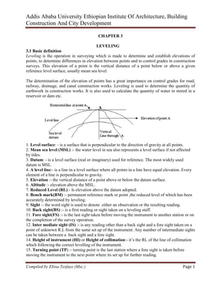
1. Level surface: - is a surface that is perpendicular to the direction of gravity at all points.
2. Mean sea level (MSL) :- the water level in sea also represents a level surface if not affected
by tides.
3. Datum: - is a level surface (real or imaginary) used for reference. The most widely used
datum is MSL.
4. A level line:- is a line in a level surface where all points in a line have equal elevation. Every
element of a line is perpendicular to gravity.
5. Elevation :- the vertical distance of a point above or below the datum surface.
6. Altitude :- elevation above the MSL.
7. Reduced Level (RL):- Is elevation above the datum adopted.
8. Bench mark(BM) :- permanent reference mark or point ,the reduced level of which has been
accurately determined by leveling.
9. Sight :- the word sight is used to denote either an observation or the resulting reading.
10. Back sight(BS) :- is a first reading or sight taken on a leveling staff.
11. Fore sight(FS) :- is the last sight taken before moving the instrument to another station or on
the completion of the survey operation.
12. Inter mediate sight (IS) :- is any reading other than a back sight and a fore sight taken on a
point of unknown R.L from the same set up of the instrument. Any number of intermediate sights
can be taken between a back sight and a fore sight.
14. Height of instrument (HI) or Height of collimation:- it’s the RL of the line of collimation
which following the correct levelling of the instrument.
15. Turning point (TP) :- turning point is the last station where a fore sight is taken before
moving the instrument to the next point where its set up for further reading.
join us on telegram:-@etconp
2. Addis Ababa University Ethiopian Institute Of Architecture, Building
Construction And City Development
Compiled by Ebisa Tesfaye (Msc.) Page 2
16. Level book: - any leveling work is recorded in a ruled suitable lines and columns. The back
sight, intermediate sights and fore sights require separate columns. Another column is normally
provided for station identification, measured distance and remarks.
3.2 USES OF LEVELLING
Leveling is widely to acquire data for mapping, engineering design and construction works.
Leveling results are used to:-
a) Design highway, railway, and canals having slope which best conform to existing topography.
b) Lay ought construction projects according to planned elevation
c) Calculate volumes of earth work
d) Investigate drainage characteristics of an area; and
e) Develop maps showing the general configuration of the ground
3.3 EQUIPMENT USED IN LEVELING
a. Level:- an instrument known as a level is required to define the horizontal plane.
join us on telegram:-@etconp
3. Addis Ababa University Ethiopian Institute Of Architecture, Building
Construction And City Development
Compiled by Ebisa Tesfaye (Msc.) Page 3
b. Staff (Rod):- is used for measuring distances vertically above or below points on which its
held relatively to a line of collimation as defined by the level.
Direct reading of the staff can be made to 0.01m and estimated readings to 0.001m.
c. Rod level: - the staff man holds the staff exactly over the mark and ensures that it is held
perfectly vertical. This is achieved with the help of a rod level.
3.4 TYPES OF LEVELLING INSTRUMENTS
Leveling instruments can be classified under three categories:-
a. Dumpy Level
In dumpy level, the line of sight is perpendicular to the vertical axis. Once the instrument is
levelled the line of sight becomes horizontal and the vertical axis becomes truly vertical provided
the instrument is in adjustment. Dumpy levels are constructed without tilting screw.
b. Tilting level
The telescope is not rigidly attached with the tribrach as the dumpy level. These types of
instruments can be tilted a small amount in the vertical plane between the telescope and the
pivot. The amount of tilt can be controlled or adjusted with the help of tilting screw.
join us on telegram:-@etconp
4. Addis Ababa University Ethiopian Institute Of Architecture, Building
Construction And City Development
Compiled by Ebisa Tesfaye (Msc.) Page 4
c. Automatic level
This type of instrument is levelled automatically by means of a compensator which insures that
the line of sight viewed through the telescope is horizontal. The advantage of this instrument is it
can be levelled with in a short period of time.
3.5 PARTS AND USES OF LEVELING INSTRUMENT
1. Trivet stage: - is a flat base plate used to attach the instrument to the tripod by the help of
fastening screw.
2. Circular bubble:- is used to make the tribrach in the same height by the help of the tripod leg.
3. Horizontal slow motion:- is used to enable coincide the vertical line with targets(staff)
4. Focusing screw:- is used to form or bring a clear image of an object in the plane of the
telescope. Focus the eye piece to get sharp cross hair and the focusing screw to get clear image.
5. Milling Ring:- is the horizontal circle reading marked in degrees from 0” to 360” with a 20
minutes division.
6. Eye piece: - is used for sighting objects (targets)
7. Tripod: - consists three legs and used for the purpose of providing support for the instrument
by fastening screw.
Automatic Level
join us on telegram:-@etconp
5. Addis Ababa University Ethiopian Institute Of Architecture, Building
Construction And City Development
Compiled by Ebisa Tesfaye (Msc.) Page 5
1. Focusing screw
2. Eyepiece
3. Foot screw
4. Milling Ring
5. Base plate (Trivet stage)
6. Horizontal slow motion
7. Circular bubble
8. Collimator (sight)
9. Object lens
3.6 CHECKING SYSTEM OF STAFF READING
When looking through the eye piece of the surveying telescope, a set of lines called the cross
hairs can be seen. These are used for taking measurements from the staff. These cross hairs are
etched on a small sheet of glass known as the diaphragm.
The main features of the telescope are
1. Object lens
2.Focusing screw
3. Focusing lens
4. Diaphragm
5. Eyepiece
The object lens, focusing lens, diaphragm and eye piece are all mounted on an optical axis called
the line of collimation or the line of sight.
This is an imaginary line which joins the optical centre of the object lens to the centre of the
cross hairs.
The four cross hairs in the diaphragm are used for checking staff
1. Vertical cross hair: - used for bisecting the staff.
2. Middle cross hair: - is used for calculating height (∆H)
join us on telegram:-@etconp
6. Addis Ababa University Ethiopian Institute Of Architecture, Building
Construction And City Development
Compiled by Ebisa Tesfaye (Msc.) Page 6
3. Upper and lower cross hairs: - are used for checking system and calculating horizontal
distance.
e.g. consider the staff readings shown in fig. below
Upper reading (UR) = 1.622m
Middle reading (MR) =1.482m
Lower reading (LR) = 1.342m
Checking
1) UR +LR = MR*2
1.622+1.342= 1.482*2
2.964 = 2.964
2) UR-MR=MR-LR
1.622-1.482 = 1.482-1.342
0.140=0.140
i.e. perfect staff reading
-The difference in reading between the upper and lower cross hair is called stadia interval.
- The difference in reading between the upper and the middle cross hair is called upper intercept
- The difference in reading between the middle and the lower cross hair is called lower intercept.
For stadia measurement on even (Level) ground the horizontal distance (HD) from the
instrument station to the rod held is equal to the stadia interval multiplied by the stadia interval
factor (SIF) of the given instrument. The SIF for any internal focusing telescope is constant 100.
join us on telegram:-@etconp
7. Addis Ababa University Ethiopian Institute Of Architecture, Building
Construction And City Development
Compiled by Ebisa Tesfaye (Msc.) Page 7
3.7 CLASSIFICATION OF LEVELLING
Difference in elevation and subsequently elevation may be determined by any one of the
following methods:
a. Direct or simple leveling
Let as assume that the elevation of station A from a given datum is known and that the elevation
of a second point B is to be determined from the same reference datum. If the two points are so
situated that they are visible from a single set up of the level, the instrument is set up
approximately mid way between the two points as in fig. below and the staff readings are taken.
Let the reading at A (ha) and B (hb) is 1.26 and 1.85 respectively. As the staff reading at B is
greater than that at A; it’s clear that the ground at B is at a lower level than that at A by 0.59.
This fact is attested by finding the difference in elevation as follows:
In leveling, the difference in elevation is always computing by subtracting the second staff
reading from the first one.
Difference in elevation =ha-hb =1.26-1.85= -0.59m
The minus sign denotes that the station B is lower from the station A by 0.59m.
Let us, Elevation of A= 1235.53m
Elevation of B = Elevation of A + (ha-hb)
= 1235.53-0.590
=1234.940m…………………… (1)
When the sign of the result of difference in elevation is plus the station B is higher from station
A.
E.g. Difference in elevation =ha’ - hb’= 1.385-0.455=+0.930m
Elevation of B = elevation of A + (ha’-hb’)
= 1235.530 + (0.930)
=1236.460m…………………… (2)
Conclusion
From (1) and (2), we note that if the difference in elevation between two points is:
i) Negative, there is a decrease in elevation of the ground at the second station; and
ii) Positive, there is an increase in elevation of the ground at the second station.
b) Trigonometric leveling
Let it be required to find the height of the building trigonometrically. In order to minimize the
effect of instrument error on the vertical angle to be measured, set the theodolite such that its
distance from the building is one to two times the height of the building.
join us on telegram:-@etconp
8. Addis Ababa University Ethiopian Institute Of Architecture, Building
Construction And City Development
Compiled by Ebisa Tesfaye (Msc.) Page 8
Procedure
The theodolite is set up at A and levelled. The vertical angle to the top of the building is
measured. The horizontal distance‘d’ from the centre of the telescope to point ‘E’ is measured
either by tape or the stadia method.
From ∆BDC, DC= dtanQ
The height AB from the ground to centre of the telescope must be added to DC in order to obtain
the height EC of the building.
- Height of building =EC=AB+DC=AB + dtanQ
If Q=30°28’29.5” and d=25.28 and AB=1.68, then
EC=1.68+25.28tan30°28’29.5”
= 16.56m
N.B in the above example, it’s assumed that A and E are on the same horizontal plane.
C. Differential leveling
The more general case occurs when the two stations whose levels are to be compared are so
situated that due to the distance apart, the difference of elevation and intervention of obstacles,
readings cannot be taken from any instrument setup on staff successively placed on them.
In this particular case, three instrument set ups are needed to determine the difference in
elevation between A and E. The shortest route between the two stations must be chosen so that as
many staff readings are practical can be taken in any one set up.
This type of leveling is known as differential leveling. Let us see know how differential leveling
is carried out:-
a. Instrument set up one (p1)
From this set up only a BS on A and a FS on B can be read. The line of sight pierces the ground
at F and consequently a reading on staff held at C cannot be obtained. Consequently B becomes a
join us on telegram:-@etconp
9. Addis Ababa University Ethiopian Institute Of Architecture, Building
Construction And City Development
Compiled by Ebisa Tesfaye (Msc.) Page 9
turning point (TP). Let us now find the difference in elevation between A and E from the staff
readings shown in the figure.
Back sight to A=0.886m
Fore sight to B=1.209m
Difference (A-B) = -0.323m (fall in elevation)
b. Instrument set up two (P2)
Back sight to B=1.943m
Intermediate sight to C=0.457m
Difference (B-C) = +1.486m (Rise in elevation)
Intermediate sight to C=0.457
Fore sight to D =0.714
Difference(C-D) = -0.257m (Fall in elevation)
c. Instrument set up three (P3)
Back sight to D=0.200m
Fore sight to E=1.857m
Difference (D-E) = -1.657m (Fall in elevation)
Difference in elevation
The difference of level between A and E is given by the algebraic sum of the difference of levels
of station A and B, B and C,C and D,D and E or equals the difference between the sum of the
back sights and the sum of the fore sights , i.e. (£BS- £FS). If the difference is positive, it denotes
that station E is higher than station A and vice versa. By way of check (£BS - £FS) must equal to
(£Rises - £Falls).
£BS=0.886+1.943+0.20=+3.029m
£FS=1.209+0.714+1.857=3.780m
£BS - £FS= -0.751m (Fall)
£Rises=1.486m
£Falls=0.323+0.257+1.657=2.237m
£Rises - £Falls= -0.751m (Fall)
Hence we note that (£BS - £FS) = (£Rises - £Falls), therefore we conclude that the arithmetic
checks
Difference in level between A and E = -0.751m
If the RL of A is known, that of E may be found out by the relation,
R.L of E= RL of A +Total BS – Total FS
join us on telegram:-@etconp
10. Addis Ababa University Ethiopian Institute Of Architecture, Building
Construction And City Development
Compiled by Ebisa Tesfaye (Msc.) Page 10
Suppose that the RL of A = 1959.925
RL of E= 1959.925-0.751=1959.174m
Note Do not move the staff from the TP before taking a B.S
3.8 Level Books and Reducing Levels
The leveling data acquired in the field is entered in a book called the level book lined in suitable
lines and columns.
The elevations of the stations where the leveling staff has been held can be obtained from the
elevation of the benchmark by one of the following two methods:-
i) Height of instrument method (HIM)
ii) Rise & Fall Method (RFM)
i) Height of instrument method (HIM)
It’s also called Height of collimation method (HCM)
The height of the plane of collimation above datum is the reduced level of known station plus the
staff reading at that station.
i.e. HPC (Height of point of collimation) =HI (Height of instrument) =RL of known station +
staff reading at that station.
RL of a point = HI – FS = (RL known BM+BS)-FS reading at a point
Standard level field book format (HI method)
Location___________ Date_____________ Observer__________ Booker_____________
Ins. No.__________
join us on telegram:-@etconp
11. Addis Ababa University Ethiopian Institute Of Architecture, Building
Construction And City Development
Compiled by Ebisa Tesfaye (Msc.) Page 11
Arithmetic check: £BS -£FS = Last RL – First RL (short but not complete)
The complete check for HI method is £RL less the first + £IS + £FS = £ (HI *no of applications).
The no
of application is the number of points whose elevations are established using the given
HI.
In this example elevation of A is already known, ele. of B, C and D is determined using the first
HI(100.628) hence for this number of application = 3 and ele. of E is established from the 2nd
HI (101.677) hence for this no
of application =1
99.064 + 99.628 + 99.418 + 100.686 + 2.564 + 2.201 = 100.628*3 + 101.677*1= 403.561
ii) Rise and Fall Method (RFM)
The rise and fall method is based on the principle that two consecutive readings from the same
instrument setting give the difference of height of the two stations where the staff was held.
If the 2nd
rod reading > first rod reading =fall
If the 2nd
rod reading < first rod reading =rise
Then RL of 2nd
station = RL of first station – fall or
= RL of first station + rise
Standard level field book (RF method)
Location_________ Date___________ Observer__________
Booker _________ Ins. No____________
-2.201 -100.00
0.686 0.686 ok
Arithmetic check: £BS -£FS = Last RL – First RL= £Rise - £Fall
The advantage and disadvantage of the two methods are
Height of instrument method (HIM)
Advantage
-involves less arithmetic and less time than the RFM. i.e. it’s more rapid than RFM.
-well adapted for reduction in the field, particularly in setting out levels for construction work,
i.e. for giving levels of roads , channels and similar construction work.
- It’s generally used for longitudinal and cross leveling operation
Disadvantage
-A mistake in an intermediate reduction may passed unnoticed
join us on telegram:-@etconp
12. Addis Ababa University Ethiopian Institute Of Architecture, Building
Construction And City Development
Compiled by Ebisa Tesfaye (Msc.) Page 12
Rise and Fall Method (RFM)
Advantage
-Affords complete check and no mistake passes unnoticed unless mistake balance
- Probably more used than the HIM for important works like earth work calculations and other
precise leveling operations.
Disadvantage
- Involves more arithmetic than the HIM.
Inverted sights
Occasionally successive FS and BS readings are taken on overhead points such as a point in the
roof of a tunnel or the girder of bridge or a cross way road. The FS taken at such point is added
to the HI to obtain the elevation of the overhead points. The BS taken on that point is subtracted
from the elevation of the overhead point to obtain the HI for the next instrument setup.
To follow the conventional reduction methods, these data are recorded as negative values in the
field book.
Example: the following reading were taken with a level on a 4.25m staff: 0.683, 1.109, 1.838,
(3.887 & 0.451) cp, 1.405, 1.896, 2.676 BM (102.120m AD) , 3.478, (4.039 & 1.835)cp, 0.649,
1.707 , -1.722(taken to the soffit of a sunshade) , 2.100(taken vertically below the soffit).
Draw up a level book & reduce the levels by a suitable method. Apply the necessary checks.
What is the head room of the sunshade?
Head room of the soffit =soffit RL-Ground RL
=104.314-100.492= 3.822m
join us on telegram:-@etconp
13. Addis Ababa University Ethiopian Institute Of Architecture, Building
Construction And City Development
Compiled by Ebisa Tesfaye (Msc.) Page 13
3.9 Longitudinal and Cross Sections
Sections are of two kinds: (a) longitudinal sections or profiles; (b) cross sections
A longitudinal section is one which follows a line which has already been proposed.
This line is usually the centre line of a proposed work, e.g. a road, railway, channel or pipe line.
A longitudinal section enables us to study the relationship between the existing ground and the
new work in the direction of its length.
Information is also required on either side of the centre line. For this purpose, cross sections are
taken in a direction normal to the centre line. In the case of a pipe line or sewer which occupies a
narrow strip of ground, cross-sections are not taken. It’s assumed that the ground within the
limits of the width of pipe-line or sewer is level in a direction normal to the centre line.
a) Profile or Longitudinal Leveling
Let us now see how the profile or longitudinal section is drawn. The profile of a road or any
other structure which has a linier development is drawn by taking elevations along the centre line
of the structure. Stakes or pages are driven in to the ground along the centre line at a given
interval where the slope of the ground shows very little or no variation and at places where a
marked change in slope occurs.
On the plan of the road which connects two towns A and B, a small river crosses the proposed
road between the stations S60 and S80. The river crosses the centre line of the road at stations
S70 and S77.The river bed is at station S74. The RLs at the different stations are shows in table.
Two instrument set-ups P1 and P2 of the centre line have been sufficient to take the readings and
the RLs have been computed with respect to a PBM and a turning point 1.
Table of Reduced Levels at centre line of Road.
Arithmetic check: £BS -£FS =3.702-5.302 = -1.60m (Fall)
Last RL – First RL= 1858.400-1860.00 = -1.60m (Fall)
join us on telegram:-@etconp
14. Addis Ababa University Ethiopian Institute Of Architecture, Building
Construction And City Development
Compiled by Ebisa Tesfaye (Msc.) Page 14
Plotting the profile
Once the RLs of the stations have been computed as shown in table 4.1 the profile of the natural
ground along the centre line can be plotted as explained below.
Procedure
a. since all the RLs are greater than 1850.00m, this elevation is taken as a datum. Its shown by
straight line drawn well below the plan of the road.
b. The stations are projected from the plan on to the datum.
c. From each of the projected stations a perpendicular is erected. On the perpendicular so erected
the corresponding elevation is plotted which provides the ordinate at that station.
d. The far ends of the ordinates are connected to obtain the profile of the natural ground along
the centre line.
In profile drawing the vertical scale is much larger than horizontal scale in order to accentuate
the difference of elevation. This is called vertical exaggeration. The longitudinal section is
plotted after applying the above methods.
The following scale is commonly used.
For high way Horizontal scale is 1:1000
Vertical scale is 1:100
For rail way Horizontal scale is 1:2000
Vertical scale is 1:200
join us on telegram:-@etconp
15. Addis Ababa University Ethiopian Institute Of Architecture, Building
Construction And City Development
Compiled by Ebisa Tesfaye (Msc.) Page 15
b) Cross sectional leveling
For laying a pipe line or sewer line only longitudinal section is adequate because the width of the
line is small. In the case of roads and railways apart from longitudinal section, cross sections at
right angles to the centre line of the alignment are required at some regular intervals. This is
necessary to know the topography of the area which required for the roads and railways and also
to compute the volume of cut and fill for the construction work. Figure A shows the plan, figure
B shows the cross section and the table shows the entry in the level book. Cross section is
usually plotted in the same horizontal and vertical scale.
join us on telegram:-@etconp
16. Addis Ababa University Ethiopian Institute Of Architecture, Building
Construction And City Development
Compiled by Ebisa Tesfaye (Msc.) Page 16
join us on telegram:-@etconp