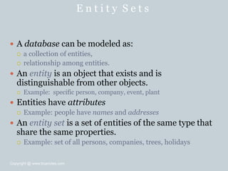
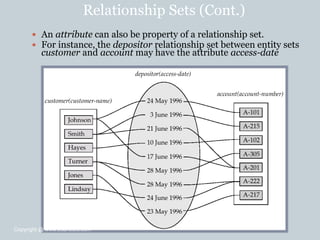
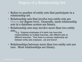
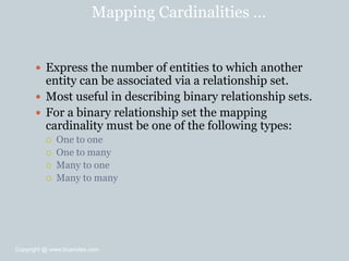
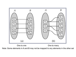
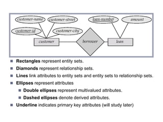
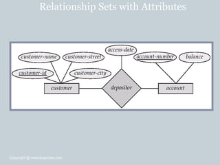
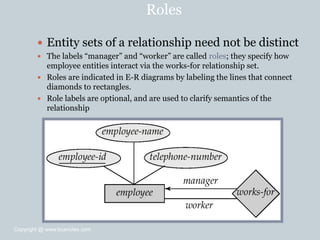
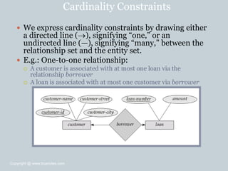
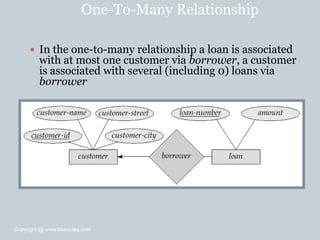
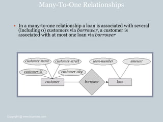
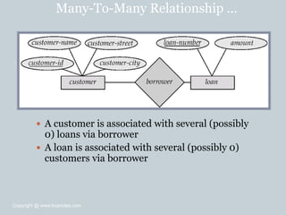
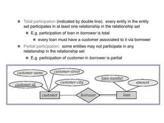
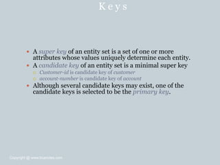
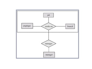
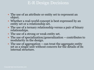
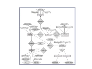
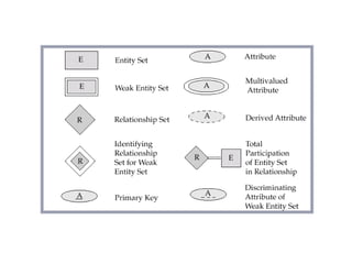
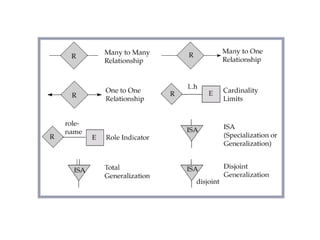
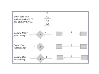
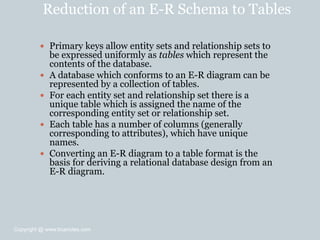
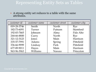
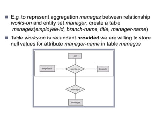
The document provides an overview of the entity-relationship model, which is used to model databases. It discusses key concepts such as entity sets, relationship sets, attributes, keys, E-R diagrams, and how to map an E-R schema to tables. The entity-relationship model allows graphical representation of the relationships between entities in a database.
This document discusses entity-relationship (ER) modeling concepts including entity sets, relationship sets, attributes, keys, ER diagrams, weak entity sets, specialization, and generalization. The key points covered are:
- Entity sets represent types of objects, relationship sets represent associations among entity sets.
- Attributes represent properties of entities and relationships. Keys uniquely identify entities.
- ER diagrams visually depict entity sets, relationship sets, attributes, and keys.
- Weak entity sets do not have their own primary key and depend on a related strong entity set.
- Specialization and generalization allow subtypes and supertypes of entities.
The document discusses key concepts in entity-relationship modeling including:
- Entity sets represent collections of real-world objects or concepts that share common properties
- Relationship sets describe associations between entities from different entity sets
- Attributes describe properties of entities and relationships
- Cardinalities specify the number of entities that can participate in a relationship
- Keys uniquely identify entities and relationships
- E-R diagrams visually represent these concepts using graphical symbols
The document provides examples and explanations of each concept to illustrate how they are used to model databases at a conceptual level prior to implementation.
The document discusses database design process which can be broken down into 5 phases - planning, analysis, design, implementation and maintenance. It describes the conceptual, logical and physical data models. The conceptual model involves entities, attributes and relationships. The logical model maps the conceptual model to tables, fields, primary and foreign keys. The physical model deals with data storage and access. The document also covers entity relationship diagrams, normalization forms and tips for effective ER diagrams.
An entity-relationship diagram (ERD) is a graphical representation that depicts the entities and relationships within an information system. An ERD shows a database's entities and the relationships between entities in a symbolic, visual way. It documents a project, clarifies features, and provides a basis for development options. Key components of an ERD include entities, relationships, attributes, and cardinality. The steps to create an ERD are to identify entities, determine interactions, analyze the nature of interactions, and draw the diagram. A good ERD model is simple, non-redundant, and flexible to adapt to future needs.
Conceptes varis sobre el model entitat relació: Conjunt d'entitats, entitats, atributs i tipus d'atributs, tipus de relacions,
cardinalitat, entitats dèbils i fortes
Entity sets, attribute, relationship, type of attribute, cardinality, relationship type, weak and strong entities. Null values, identifier
The document discusses weak and strong syllables in English. It defines weak and strong syllables and provides examples of different types of weak syllables based on their vowel sounds or syllabic consonants. It also discusses how weak syllables are pronounced compared to strong syllables and their role in keeping the stress-timed rhythm of English speech.
This document discusses entity relationship (ER) modeling concepts including:
- Strong entities that can be uniquely identified by their attributes versus weak entities that require a foreign key.
- Weak entities must have an identifying relationship with a strong entity called the owner entity.
- The identifying relationship is many-to-one from the weak to owner entity and the weak entity's participation is total.
- A discriminator attribute allows distinguishing among weak entities related to the same owner entity.
The document discusses key concepts in entity relationship diagrams including entities, attributes, entity sets, relationships, relationship sets, cardinality, roles, and identifiers. It defines entities as people, places, objects or events and describes their attributes. It also covers the different types of relationships that can exist between entities like one-to-one, one-to-many, many-to-one, and many-to-many. Finally, it discusses primary keys, foreign keys, and the importance of identifying keys for looking up and linking information between tables.
The document discusses weak and strong syllables in English. Weak syllables tend to be unstressed and may contain reduced vowel sounds like schwa. They often occur in function words like "the" and prefixes/suffixes. Strong syllables are stressed and have clearer vowel sounds. The types of segments that can make up syllables and examples of words with different syllable structures are provided.
Database Modeling Using Entity.. Weak And Strong Entity Typesaakanksha s
Data modeling is a technique for organizing data in a system by applying formal modeling methods. It involves creating conceptual, logical, and physical data models. Key elements of data modeling include entities, attributes, relationships, domains, keys, and cardinality. Weak entities differ from strong entities in that weak entities do not have attributes to form a primary key and instead inherit their primary key from the strong entity they are dependent on through an identifying relationship.
The document provides an overview of entity-relationship (ER) modeling concepts used in database design. It defines key terms like entities, attributes, relationships, and cardinalities. It explains how ER diagrams visually represent these concepts using symbols like rectangles, diamonds, and lines. The document also discusses entity types, relationship degrees, key attributes, weak entities, and how to model one-to-one, one-to-many, many-to-one, and many-to-many relationships. Overall, the document serves as a guide to basic ER modeling principles for conceptual database design.
An Object Oriented DBMS stores data as objects that use object-oriented concepts like classes, inheritance, and encapsulation. Objects have attributes that can be simple like integers or complex like collections. Classes group similar objects and subclasses inherit attributes and behaviors from superclasses. Objects communicate through messages that invoke methods. The DBMS maps classes and objects to tables and tuples in a relational database, which loses some semantic information about class hierarchies.
The document discusses the entity-relationship (E-R) data model. It defines key concepts in E-R modeling including entities, attributes, entity sets, relationships, and relationship sets. It describes different types of attributes and relationships. It also explains how to represent E-R diagrams visually using symbols like rectangles, diamonds, and lines to depict entities, relationships, keys, and cardinalities. Primary keys, foreign keys, and weak entities are also covered.
This document provides an overview of database management systems and related concepts. It discusses data hierarchy, traditional file processing, the database approach to data management, features and capabilities of database management systems, database schemas, components of database management systems, common data models including hierarchical, network, and relational models, and the process of data normalization.
The document provides an overview of entity-relationship (E-R) modeling concepts including:
- Entity sets represent collections of real-world entities that share common properties
- Relationship sets define associations between entity sets
- Attributes provide additional information about entities and relationships
- Keys uniquely identify entities and relationships
- Cardinalities constrain how entities can participate in relationships
- E-R diagrams visually depict entity sets, attributes, relationships and constraints.
The small words that manage the grammar in English have two different pronunciations. These are called weak and strong forms. The weak forms are unstressed and the strong forms stressed. Most weak forms have either schwa or short 'i' vowel sounds and they are difficult to hear. These words are very important for the pronunciation of English grammar--they are like the gluer in the phonetic system.
The document provides an overview of the entity-relationship model for database design. It discusses key concepts such as entities, attributes, relationships, and cardinality constraints. It also covers advanced topics like weak entities, generalization/specialization, and aggregation. The entity-relationship model involves representing real-world objects and associations between objects using a graphical diagram to design the database at a conceptual level.
This document provides an overview of entity-relationship (ER) modeling concepts including entity sets, relationship sets, attributes, keys, ER diagrams, specialization, generalization, aggregation, and design issues. It defines core ER concepts like entities, relationships, and attributes. It describes how ER diagrams visually represent these concepts using symbols like rectangles for entities and diamonds for relationships. It also covers advanced topics such as weak entities, cardinalities, and converting non-binary relationships to binary form.
The document provides an overview of entity-relationship (ER) modeling concepts including:
- Entity sets represent collections of real-world objects or concepts that share common properties
- Relationship sets represent associations between entity sets
- ER diagrams use graphical symbols like rectangles, diamonds, and lines to represent entity sets, relationship sets, and attributes
- Mapping cardinalities define the number of entities in one set that can be associated with entities in another set through a relationship
- Keys uniquely identify entities and relationships and primary keys are selected from candidate keys
- The document discusses entity-relationship (E-R) modeling concepts including entity sets, relationship sets, attributes, keys, E-R diagrams, mapping cardinalities, and design issues when converting between binary and non-binary relationships.
- It provides examples of how to represent various relationship types like one-to-one, one-to-many, many-to-one, and many-to-many using E-R diagrams with lines and arrows to show cardinality constraints.
- Guidelines are given for choosing between entity sets vs attributes and relationship sets, and converting non-binary relationships to binary form while preserving semantics.
The document provides an overview of entity-relationship (ER) modeling concepts including:
- Entity sets and relationship sets which form the basic constructs of an ER model
- Attributes, keys, and cardinality constraints which provide further details on entities and relationships
- ER diagrams which visually depict the ER model through graphical symbols
- Additional ER modeling features such as weak entities, specialization, and aggregation
The document concludes by discussing how an ER schema can be reduced to tables to represent the data in a relational database.
The document discusses database design concepts including entity sets, relationship sets, attributes, keys, and modeling techniques. It provides examples of how to represent various database design concepts in an entity-relationship (E-R) diagram including entities, relationships, cardinalities, participation constraints, weak entity sets, and translating n-ary relationships to binary relationships. Design choices such as using entity sets vs. attributes and relationship sets are also covered.
The sole purpose of sharing these slides are to educate the beginners of IT and Computer Science/Engineering. Credits should go to the referred material and also CICRA campus, Colombo 4, Sri Lanka where I taught these in 2017.
This document discusses entity-relationship (E-R) modeling concepts including entity sets, relationship sets, E-R diagrams, keys, attributes, weak entity sets, specialization, generalization, aggregation, and converting an E-R schema to tables. It provides examples and definitions for each concept in 2-3 sentences.
This document provides an overview of entity-relationship (E-R) modeling concepts for database design. It defines key E-R modeling elements including entity sets, relationship sets, attributes, keys, and cardinality constraints. It also covers E-R diagram notation and more advanced concepts such as weak entity sets, generalization/specialization, and aggregation. The goal of E-R modeling is to represent the structure and semantics of an organization's data to facilitate database design.
The document provides information about database management systems and the relational database model. It discusses data models, entity relationship modeling, relational databases, normalization of database tables, and relational database design. Key topics covered include the entity relationship model, E-R diagrams, relationship sets, attributes, keys, normalization forms, and designing normalized database tables.
The document discusses entity-relationship (ER) diagrams and database design. It defines key concepts in ER diagrams like entities, attributes, relationships and how they are represented. It explains how to start building an ER diagram by defining entities and relationships based on a narrative. Different types of relationships and how they are drawn are covered, along with cardinality, keys, and other symbols used in ER diagrams. The document provides an example of an ER diagram for a banking system and discusses how an ER diagram can be converted into a relational database with tables.
The document discusses the Entity-Relationship (E-R) model, which was proposed by Dr. Peter Chen in the 1970s as a way to model real-world entities and their relationships. The E-R model uses entities, attributes, and relationships, and allows these concepts to be visually represented in E-R diagrams using basic graphical symbols like rectangles, ellipses, and diamonds. The document also covers E-R modeling concepts like keys, entity types, relationship types, participation constraints, and weak entity sets.
The document provides an overview of conceptual database design using the Entity-Relationship (ER) model. It describes the basic constructs of the ER model including entities, relationships, attributes, and additional features like weak entities, inheritance hierarchies, and aggregation. It also discusses modeling choices like representing concepts as entities or attributes, binary vs n-ary relationships. Constraints that can be expressed in the ER model are covered, along with the subjective nature of ER design.
Requirements of a Conceptual Data Model
Expressiveness: should be expressive enough to allow modeling of different types of relationships, objects and constraints of the miniworld.
Simplicity: non-specialists should be able to understand
Diagrammatic Representation: to ease interpretation
Formality: There should be no ambiguity in the specification
Data models are used to describe data, relationships, semantics, and constraints. They help understand the meaning of data and facilitate communication about requirements. Entity relationship modeling represents entities as rectangles, attributes as ellipses, and relationships as diamonds. Entities can be weak or strong, with weak entities dependent on other entities. Relationships have cardinalities like one-to-one, one-to-many, and many-to-many. Keys uniquely identify entities and relationships. Weak entities lack their own primary key and are dependent on a strong entity.
This document discusses the entity-relationship (ER) model for conceptual database design. It defines key concepts like entities, attributes, relationships, keys, and participation constraints. Entities can be strong or weak, and attributes can be simple, composite, multi-valued, or derived. Relationships associate entities and can specify cardinality like one-to-one, one-to-many, or many-to-many. The ER model diagrams the structure and constraints of a database before its logical and physical implementation.
This document provides an overview of the key concepts in entity-relationship modeling including the three main elements - entity sets, attributes, and relationships. It defines these elements and provides examples like entities for departments, professors, students. It also describes other ER modeling concepts such as keys, single and multi-valued attributes, mapping cardinalities, participation constraints, weak entity sets, and identifying weak entity types. The document is presented as a lecture on ER modeling with examples to illustrate each concept.
The document discusses the process of database design and the entity-relationship (E-R) model. It covers the conceptual, logical, and physical design phases. It also explains the key concepts of the E-R model including entities, attributes, relationships, keys, and cardinality constraints. E-R diagrams provide a way to visually represent an enterprise schema using these basic E-R modeling elements and their relationships.
The document summarizes key concepts of the Entity-Relationship (E-R) model including:
- Entity sets represent groups of related entities and can have subclasses. Relationships connect entity sets and can be binary, ternary or higher.
- Weak entities depend on other entities, and their existence is defined by an identifying relationship. Discriminators uniquely identify weak entities.
- Keys uniquely identify entities in an entity set and must be designated. Relationships can have attributes and roles to distinguish relationships.
Business law for the students of undergraduate level. The presentation contains the summary of all the chapters under the syllabus of State University, Contract Act, Sale of Goods Act, Negotiable Instrument Act, Partnership Act, Limited Liability Act, Consumer Protection Act.
A Critical Study of ICC Prosecutor's Move on GAZA WarNilendra Kumar
ICC Prosecutor Karim Khan's proposal to its judges seeking permission to prosecute Israeli leaders and Hamas commanders for crimes against the law of war has serious ramifications and calls deep scrutiny.
Corporate Governance : Scope and Legal Frameworkdevaki57
CORPORATE GOVERNANCE
MEANING
Corporate Governance refers to the way in which companies are governed and to what purpose. It identifies who has power and accountability, and who makes decisions. It is, in essence, a toolkit that enables management and the board to deal more effectively with the challenges of running a company.
सुप्रीम कोर्ट ने यह भी माना था कि मजिस्ट्रेट का यह कर्तव्य है कि वह सुनिश्चित करे कि अधिकारी पीएमएलए के तहत निर्धारित प्रक्रिया के साथ-साथ संवैधानिक सुरक्षा उपायों का भी उचित रूप से पालन करें।
Safeguarding Against Financial Crime: AML Compliance Regulations DemystifiedPROF. PAUL ALLIEU KAMARA
To ensure the integrity of financial systems and combat illicit financial activities, understanding AML (Anti-Money Laundering) compliance regulations is crucial for financial institutions and businesses. AML compliance regulations are designed to prevent money laundering and the financing of terrorist activities by imposing specific requirements on financial institutions, including customer due diligence, monitoring, and reporting of suspicious activities (GitHub Docs).
Indonesian Manpower Regulation on Severance Pay for Retiring Private Sector E...AHRP Law Firm
Law Number 13 of 2003 on Manpower has been partially revoked and amended several times, with the latest amendment made through Law Number 6 of 2023. Attention is drawn to a specific part of the Manpower Law concerning severance pay. This aspect is undoubtedly one of the most crucial parts regulated by the Manpower Law. It is essential for both employers and employees to abide by the law, fulfill their obligations, and retain their rights regarding this matter.
1. E n t i t y – R e l a t i o n s h i p M o d e l
Entity Sets
Relationship Sets
Design Issues
Mapping Constraints
Keys
E-R Diagram
Extended E-R Features
Design of an E-R Database Schema
Reduction of an E-R Schema to
Tables
Copyright @ www.bcanotes.com
2. E n t i t y S e t s
A database can be modeled as:
a collection of entities,
relationship among entities.
An entity is an object that exists and is
distinguishable from other objects.
Example: specific person, company, event, plant
Entities have attributes
Example: people have names and addresses
An entity set is a set of entities of the same type that
share the same properties.
Example: set of all persons, companies, trees, holidays
Copyright @ www.bcanotes.com
3. E n t i t y S e t s c u s t o m e r a n d l o a n
customer-id customer- customer- customer- loan- amount
name street city number
Copyright @ www.bcanotes.com
4. A t t r i b u t e s
An entity is represented by a set of attributes, that is
descriptive properties possessed by all members of
an entity set.
Domain – the set of permitted values for each
attribute
Attribute types:
Simple and composite attributes.
Single-valued and multi-valued attributes
E.g. multivalued attribute: phone-numbers
Derived attributes
Can be computed from other attributes
E.g. age, given date of birth
Example:
customer = (customer-id, customer-name,
customer-street, customer-city)
loan = (loan-number, amount)
Copyright @ www.bcanotes.com
5. C o m p o s i t e A t t r i b u t e s
Copyright @ www.bcanotes.com
6. R e l a t i o n s h i p S e t s
A relationship is an association among several
entities
Example:
Hayes depositor A-102
customer entityrelationship setaccount entity
Example:
(Hayes, A-102) depositor
Copyright @ www.bcanotes.com
8. Relationship Sets (Cont.)
An attribute can also be property of a relationship set.
For instance, the depositor relationship set between entity sets
customer and account may have the attribute access-date
Copyright @ www.bcanotes.com
9. Degree of a Relationship Set
Refers to number of entity sets that participate in a
relationship set.
Relationship sets that involve two entity sets are
binary (or degree two). Generally, most relationship
sets in a database system are binary.
Relationship sets may involve more than two entity
sets.
Relationships between more than two entity sets are
rare. Most relationships are binary.
E.g. Suppose employees of a bank may have jobs
(responsibilities) at multiple branches, with different jobs at
different branches. Then there is a ternary relationship set
between entity sets employee, job and branch
Copyright @ www.bcanotes.com
10. Mapping Cardinalities …
Express the number of entities to which another
entity can be associated via a relationship set.
Most useful in describing binary relationship sets.
For a binary relationship set the mapping
cardinality must be one of the following types:
One to one
One to many
Many to one
Many to many
Copyright @ www.bcanotes.com
11. Mapping Cardinalities …
One to one One to many
Note: Some elements in A and B may not be mapped to any elements in the other set
Copyright @ www.bcanotes.com
12. Mapping Cardinalities ...
Many to one Many to many
Note: Some elements in A and B may not be mapped to any elements in the other set
Copyright @ www.bcanotes.com
13. Mapping Cardinalities affect ER Design
Can make access-date an attribute of account, instead of a
relationship attribute, if each account can have only one customer
I.e., the relationship from account to customer is many to one,
or equivalently, customer to account is one to many
Copyright @ www.bcanotes.com
14. E - R D i a g r a m s
Rectangles represent entity sets.
Diamonds represent relationship sets.
Lines link attributes to entity sets and entity sets to relationship sets.
Ellipses represent attributes
Double ellipses represent multivalued attributes.
Dashed ellipses denote derived attributes.
Underline indicates primary key attributes (will study later)
Copyright @ www.bcanotes.com
15. E-R Diagram With Composite, Multivalued, and Derived
Attributes
Copyright @ www.bcanotes.com
17. Roles
Entity sets of a relationship need not be distinct
The labels ―manager‖ and ―worker‖ are called roles; they specify how
employee entities interact via the works-for relationship set.
Roles are indicated in E-R diagrams by labeling the lines that connect
diamonds to rectangles.
Role labels are optional, and are used to clarify semantics of the
relationship
Copyright @ www.bcanotes.com
18. Cardinality Constraints
We express cardinality constraints by drawing either
a directed line (), signifying ―one,‖ or an
undirected line (—), signifying ―many,‖ between the
relationship set and the entity set.
E.g.: One-to-one relationship:
A customer is associated with at most one loan via the
relationship borrower
A loan is associated with at most one customer via borrower
Copyright @ www.bcanotes.com
19. One-To-Many Relationship
In the one-to-many relationship a loan is associated
with at most one customer via borrower, a customer
is associated with several (including 0) loans via
borrower
Copyright @ www.bcanotes.com
20. Many-To-One Relationships
In a many-to-one relationship a loan is associated with several
(including 0) customers via borrower, a customer is
associated with at most one loan via borrower
Copyright @ www.bcanotes.com
21. Many-To-Many Relationship …
A customer is associated with several (possibly
0) loans via borrower
A loan is associated with several (possibly 0)
customers via borrower
Copyright @ www.bcanotes.com
22. Participation of an Entity Set in a Relationship Set
Total participation (indicated by double line): every entity in the entity
set participates in at least one relationship in the relationship set
E.g. participation of loan in borrower is total
every loan must have a customer associated to it via borrower
Partial participation: some entities may not participate in any
relationship in the relationship set
E.g. participation of customer in borrower is partial
Copyright @ www.bcanotes.com
23. K e y s
A super key of an entity set is a set of one or more
attributes whose values uniquely determine each entity.
A candidate key of an entity set is a minimal super key
Customer-id is candidate key of customer
account-number is candidate key of account
Although several candidate keys may exist, one of the
candidate keys is selected to be the primary key.
Copyright @ www.bcanotes.com
24. Keys for Relationship Sets
The combination of primary keys of the participating
entity sets forms a super key of a relationship set.
(customer-id, account-number) is the super key of depositor
NOTE: this means a pair of entity sets can have at most one
relationship in a particular relationship set.
E.g. if we wish to track all access-dates to each account by each
customer, we cannot assume a relationship for each access. We can use
a multivalued attribute though
Must consider the mapping cardinality of the
relationship set when deciding the what are the
candidate keys
Need to consider semantics of relationship set in
selecting the primary key in case of more than one
candidate key
Copyright @ www.bcanotes.com
25. E-R Diagram with a Ternary Relationship
Copyright @ www.bcanotes.com
26. Cardinality Constraints on Ternary Relationship
We allow at most one arrow out of a ternary (or greater
degree) relationship to indicate a cardinality constraint
E.g. an arrow from works-on to job indicates each
employee works on at most one job at any branch.
If there is more than one arrow, there are two ways of
defining the meaning.
E.g a ternary relationship R between A, B and C with arrows to B
and C could mean
1. each A entity is associated with a unique entity from B and C or
2. each pair of entities from (A, B) is associated with a unique C
entity, and each pair (A, C) is associated with a unique B
Each alternative has been used in different formalisms
To avoid confusion we outlaw more than one arrow
Copyright @ www.bcanotes.com
27. Design Issues
Use of entity sets vs. attributes
Choice mainly depends on the structure of the enterprise
being modeled, and on the semantics associated with the
attribute in question.
Use of entity sets vs. relationship sets
Possible guideline is to designate a relationship set to
describe an action that occurs between entities
Binary versus n-ary relationship sets
Although it is possible to replace any nonbinary (n-ary, for
n > 2) relationship set by a number of distinct binary
relationship sets, a n-ary relationship set shows more
clearly that several entities participate in a single
relationship.
Placement of relationship attributes
Copyright @ www.bcanotes.com
28. Weak Entity Sets
An entity set that does not have a primary key is referred
to as a weak entity set.
The existence of a weak entity set depends on the
existence of a identifying entity set
it must relate to the identifying entity set via a total, one-to-many
relationship set from the identifying to the weak entity set
Identifying relationship depicted using a double diamond
The discriminator (or partial key) of a weak entity set is
the set of attributes that distinguishes among all the
entities of a weak entity set.
The primary key of a weak entity set is formed by the
primary key of the strong entity set on which the weak
entity set is existence dependent, plus the weak entity
set’s discriminator.
Copyright @ www.bcanotes.com
29. Weak Entity Sets (Cont.)
We depict a weak entity set by double rectangles.
We underline the discriminator of a weak entity set with a
dashed line.
payment-number – discriminator of the payment entity
set
Primary key for payment – (loan-number, payment-
number)
Copyright @ www.bcanotes.com
30. Weak Entity Sets (Cont.)
Note: the primary key of the strong entity set is not
explicitly stored with the weak entity set, since it is
implicit in the identifying relationship.
If loan-number were explicitly stored, payment could be
made a strong entity, but then the relationship between
payment and loan would be duplicated by an implicit
relationship defined by the attribute loan-number
common to payment and loan
Copyright @ www.bcanotes.com
31. More Weak Entity Set Examples
In a university, a course is a strong entity and a
course-offering can be modeled as a weak entity
The discriminator of course-offering would be
semester (including year) and section-number (if
there is more than one section)
If we model course-offering as a strong entity we
would model course-number as an attribute.
Then the relationship with course would be implicit
in the course-number attribute
Copyright @ www.bcanotes.com
32. Specialization
Top-down design process; we designate subgroupings
within an entity set that are distinctive from other entities
in the set.
These subgroupings become lower-level entity sets that
have attributes or participate in relationships that do not
apply to the higher-level entity set.
Depicted by a triangle component labeled ISA (E.g.
customer ―is a‖ person).
Attribute inheritance – a lower-level entity set inherits
all the attributes and relationship participation of the
higher-level entity set to which it is linked.
Copyright @ www.bcanotes.com
34. Generalization
A bottom-up design process – combine a number of entity sets
that share the same features into a higher-level entity set.
Specialization and generalization are simple inversions of each
other; they are represented in an E-R diagram in the same
way.
The terms specialization and generalization are used
interchangeably.
Copyright @ www.bcanotes.com
35. Specialization and Generalization…
Can have multiple specializations of an entity set
based on different features.
E.g. permanent-employee vs. temporary-employee,
in addition to officer vs. secretary vs. teller
Each particular employee would be
a member of one of permanent-employee or temporary-
employee,
and also a member of one of officer, secretary, or teller
The ISA relationship also referred to as superclass -
subclass relationship
Copyright @ www.bcanotes.com
36. Design Constraints on a Specialization/ Generalization
Constraint on which entities can be members of a
given lower-level entity set.
condition-defined
E.g. all customers over 65 years are members of senior-
citizen entity set; senior-citizen ISA person.
user-defined
Constraint on whether or not entities may belong
to more than one lower-level entity set within a
single generalization.
Disjoint
an entity can belong to only one lower-level entity set
Noted in E-R diagram by writing disjoint next to the ISA
triangle
Overlapping
an entity can belong to more than one lower-level entity set
Copyright @ www.bcanotes.com
37. Design Constraints on a Specialization/ Generalization
…
Completeness constraint -- specifies whether or not
an entity in the higher-level entity set must belong to
at least one of the lower-level entity sets within a
generalization.
total : an entity must belong to one of the lower-level entity
sets
partial: an entity need not belong to one of the lower-level
entity sets
Copyright @ www.bcanotes.com
38. Aggregation
Consider the ternary relationship works-on, which we saw earlier
Suppose we want to record managers for tasks performed by an
employee at a branch
Copyright @ www.bcanotes.com
39. Aggregation (Cont.)
Relationship sets works-on and manages represent
overlapping information
Every manages relationship corresponds to a works-on relationship
However, some works-on relationships may not correspond to any
manages relationships
So we can’t discard the works-on relationship
Eliminate this redundancy via aggregation
Treat relationship as an abstract entity
Allows relationships between relationships
Abstraction of relationship into new entity
Without introducing redundancy, the following diagram
represents:
An employee works on a particular job at a particular branch
An employee, branch, job combination may have an associated
manager
Copyright @ www.bcanotes.com
41. E-R Design Decisions
The use of an attribute or entity set to represent an
object.
Whether a real-world concept is best expressed by an
entity set or a relationship set.
The use of a ternary relationship versus a pair of binary
relationships.
The use of a strong or weak entity set.
The use of specialization/generalization – contributes to
modularity in the design.
The use of aggregation – can treat the aggregate entity
set as a single unit without concern for the details of its
internal structure.
Copyright @ www.bcanotes.com
42. E-R Diagram for a Banking Enterprise
Copyright @ www.bcanotes.com
46. Reduction of an E-R Schema to Tables
Primary keys allow entity sets and relationship sets to
be expressed uniformly as tables which represent the
contents of the database.
A database which conforms to an E-R diagram can be
represented by a collection of tables.
For each entity set and relationship set there is a
unique table which is assigned the name of the
corresponding entity set or relationship set.
Each table has a number of columns (generally
corresponding to attributes), which have unique
names.
Converting an E-R diagram to a table format is the
basis for deriving a relational database design from an
E-R diagram.
Copyright @ www.bcanotes.com
47. Representing Entity Sets as Tables
A strong entity set reduces to a table with the same
attributes.
Copyright @ www.bcanotes.com
48. Composite and Multivalued Attributes
Composite attributes are flattened out by creating a
separate attribute for each component attribute
E.g. given entity set customer with composite attribute name with
component attributes first-name and last-name the table
corresponding to the entity set has two attributes
name.first-name and name.last-name
A multivalued attribute M of an entity E is represented
by a separate table EM
Table EM has attributes corresponding to the primary key of E and
an attribute corresponding to multivalued attribute M
E.g. Multivalued attribute dependent-names of employee is
represented by a table
employee-dependent-names( employee-id, dname)
Each value of the multivalued attribute maps to a separate row of
the table EM
E.g., an employee entity with primary key John and
dependents Johnson and Johndotir maps to two rows:
(John, Johnson) and (John, Johndotir)
Copyright @ www.bcanotes.com
49. Representing Weak Entity Sets
A weak entity set becomes a table that includes a column for
the primary key of the identifying strong entity set
Copyright @ www.bcanotes.com
50. Representing Relationship Sets as Tables
A many-to-many relationship set is represented as a table with
columns for the primary keys of the two participating entity sets,
and any descriptive attributes of the relationship set.
E.g.: table for relationship set borrower
Copyright @ www.bcanotes.com
51. Redundancy of Tables
Many-to-one and one-to-many relationship sets that are total
on the many-side can be represented by adding an extra
attribute to the many side, containing the primary key of the
one side
E.g.: Instead of creating a table for relationship account-
branch, add an attribute branch to the entity set account
Copyright @ www.bcanotes.com
52. Redundancy of Tables (Cont.)
For one-to-one relationship sets, either side can be
chosen to act as the ―many‖ side
That is, extra attribute can be added to either of the tables
corresponding to the two entity sets
If participation is partial on the many side,
replacing a table by an extra attribute in the relation
corresponding to the ―many‖ side could result in null
values
The table corresponding to a relationship set linking
a weak entity set to its identifying strong entity set is
redundant.
E.g. The payment table already contains the information that
would appear in the loan-payment table (i.e., the columns
loan-number and payment-number).
Copyright @ www.bcanotes.com
53. Representing Specialization as Tables
Method 1:
Form a table for the higher level entity
Form a table for each lower level entity set, include primary key of
higher level entity set and local attributes
table table attributes
person name, street, city
customer name, credit-rating
employee name, salary
Drawback: getting information about, e.g., employee requires
accessing two tables
Copyright @ www.bcanotes.com
54. Representing Specialization as Tables…
Method 2:
Form a table for each entity set with all local and inherited attributes
table table attributes
person name, street, city
customer name, street, city, credit-rating
employee name, street, city, salary
If specialization is total, table for generalized entity (person) not
required to store information
Can be defined as a ―view‖ relation containing union of
specialization tables
But explicit table may still be needed for foreign key constraints
Drawback: street and city may be stored redundantly for persons
who are both customers and employees
Copyright @ www.bcanotes.com
55. Relations Corresponding to Aggregation
To represent aggregation, create a table containing
primary key of the aggregated relationship,
the primary key of the associated entity set
Any descriptive attributes
Copyright @ www.bcanotes.com
56. Relations Corresponding to Aggregation…
E.g. to represent aggregation manages between relationship
works-on and entity set manager, create a table
manages(employee-id, branch-name, title, manager-name)
Table works-on is redundant provided we are willing to store
null values for attribute manager-name in table manages
Copyright @ www.bcanotes.com