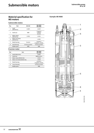
Downloaded 45 times

![3
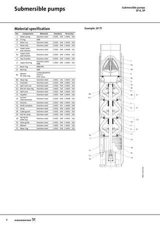
Submersible pumps
SP A, SPGeneral data
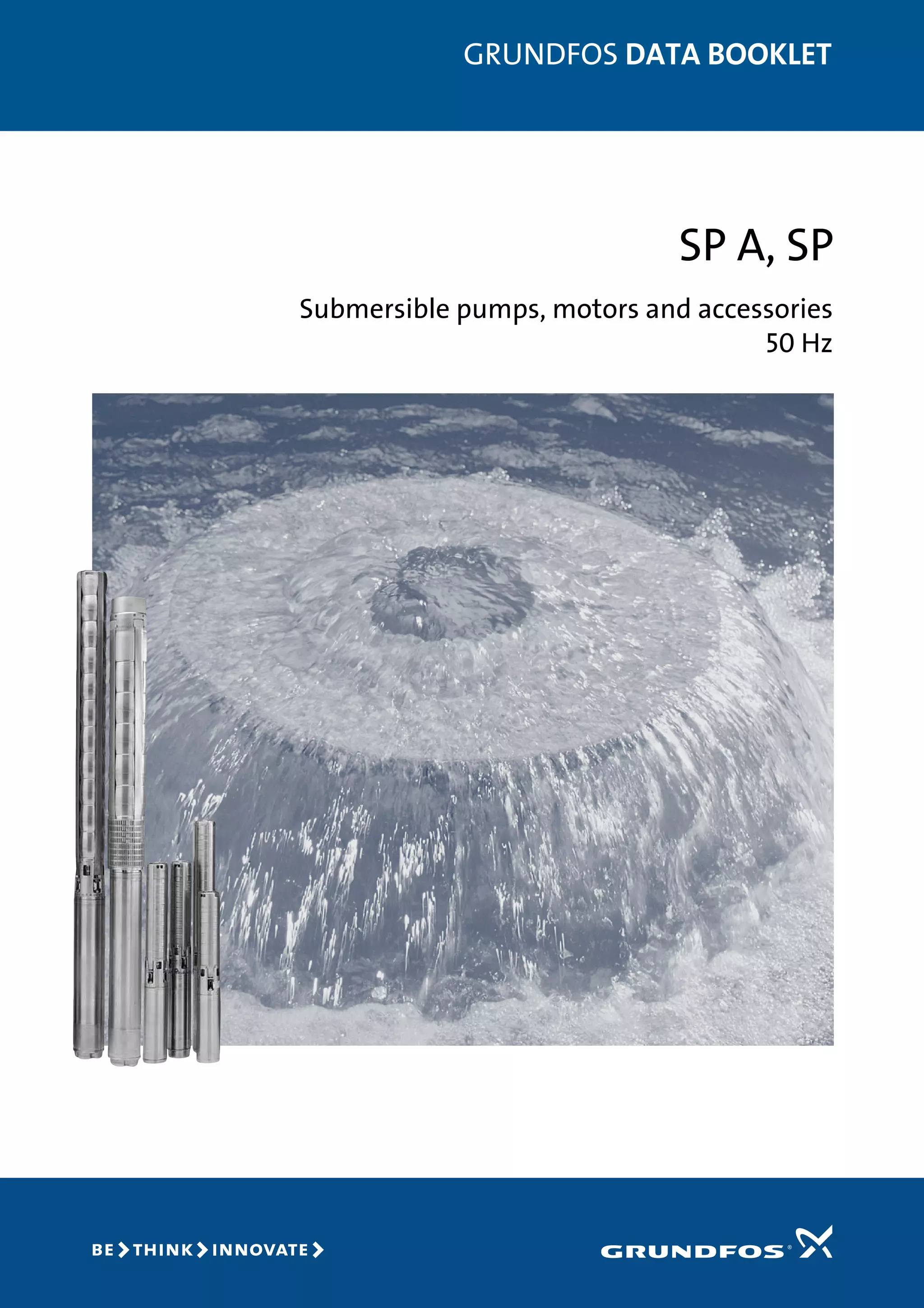
Performance range
TM0072544702
1 2 4 6 8 10 20 40 60 80 100 200 400
Q [m³/h]
10
20
40
60
80
100
200
400
600
H
[m]
100
200
400
600
800
1000
2000
4000
6000
p
[kPa]
0.4 0.6 0.8 1 2 4 6 8 10 20 40 60 Q [l/s]
SP
50 Hz
SP215
SP160
SP125
SP77
SP60
SP46
SP30
SP17
SP14A
SP8A
SP5A
SP2A
SP1A
SP3A
SP95](https://image.slidesharecdn.com/submersiblepump-grundfos-180406163941/85/Submersible-pump-GRUNDFOS-3-320.jpg)
![5
General data Submersible pumps
SP A, SP
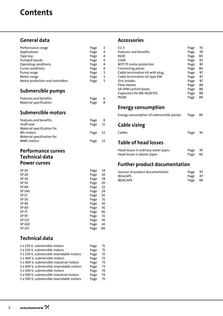
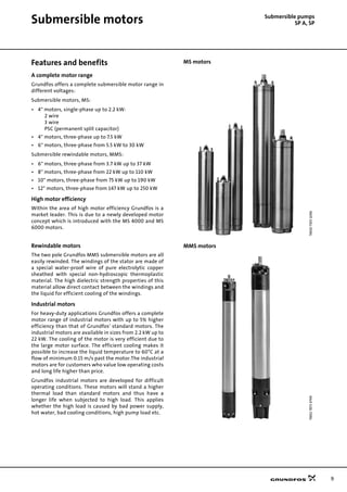
Pump range
Motor range
Motor protection and controllers
Type SP1A SP2A SP3A SP5A SP8A SP14A SP17 SP30 SP46 SP60 SP77 SP95 SP125 SP160 SP215
Steel: DIN 1.4301
AISI 304
Steel: DIN 1.4401
AISI 316
Steel: DIN 1.4539
AISI 904L
Connection Rp 1¼
Rp 1¼
(R 1¼)
Rp 1¼
Rp 1½
(R 1½)
Rp 2
(R 2)
Rp 2
Rp 2½
(R 3)
Rp 3
(R 3)
Rp 3
Rp 4
(R 4)
Rp 3
Rp 4
Rp 5 Rp 5 Rp 6 Rp 6 Rp 6
Flange connection:
Grundfos flange
5" 5" 6" 6" 6"
Figures in brackets ( ) indicate connection for pumps in sleeve.
Motor output
[kW]
0.37 0.55 0.75 1.1 1.5 2.2 3.0 3.7 4.0 5.5 7.5 9.2 11 13 15 18.5 22 26 30 37 45 55 63 75 92 110 132 147 170 190 220 250
Single-phase
Three-phase
Industrial motor
Rewindable motor
Steel: DIN 1.4301
AISI 304
Steel: DIN 1.4301
and cast iron
Steel: DIN 1.4401
AISI 316
Steel: DIN 1.4539
AISI 904L
Built-in temperature
transmitter in motor
Direct-on-line starting is recommended up to 75 kW.
Soft starter or autotransformer is recommended above 75 kW.
Motors with star/delta are available from 5.5 kW.
Motor output
[kW]
0.37 0.55 0.75 1.1 1.5 2.2 3.0 3.7 4.0 5.5 7.5 9.2 11 13 15 18.5 22 26 30 37 45 55 63 75 92 110 132 147 170 190 220 250
MTP 75
CU 3
Pt100
Zinc anode
Vertical flow sleeve
Horizontal flow sleeve
SA-SPM
R100
RS-485 communica-
tion module
G100
SM100
sensor module
Requires motor with built-in temperature transmitter.
Motor protection of single-phase motors, see "Technical data" page 71.](https://image.slidesharecdn.com/submersiblepump-grundfos-180406163941/85/Submersible-pump-GRUNDFOS-5-320.jpg)
![6
Submersible pumps
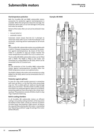
SP A, SPSubmersible pumps
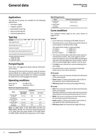
Features and benefits
A wide pump range
Grundfos offers submersible pumps with energy-effi-
cient duty points ranging from 1 to 280 m3
/h. The pump
range consists of many pump sizes - and each pump size
is available with an optional number of stages to match
any duty point.
High pump efficiency
Often pump efficiency is a neglected factor compared to
the price. However, the observant user will notice that
price variations are without importance to water supply
economics compared to the importance of pump and
motor efficiencies.
Example:
When pumping 200 m3
/h with a head of 100 m for a
period of 10 years EURO 60,000 will be saved if a pump/
motor having a 10% higher efficiency is chosen and the
price is EURO 0.10 per kWh.
Material and pumped liquids
Grundfos offers a complete range of pumps and motors
which as a standard are made completely of stainless
steel to DIN W.-Nr. 1.4301 (AISI 304). This provides for
good wear resistance and a reduced risk of corrosion
when pumping ordinary cold water with a minor
content of chloride.
A pump range made of upgraded stainless steel is avail-
able for more aggressive liquids:
SP N: DIN W.-Nr. 1.4401 (AISI 316)
SP R: DIN W.-Nr. 1.4539 (AISI 904L)
Alternatively, a complete range of zinc anodes for
cathodic protection is available, see page 87. For
example this may be advisable for sea water applica-
tions.
For slightly polluted liquids containing for example oil,
Grundfos offers a complete range (SP NE) in stainless
steel to DIN W.-Nr. 1.4401 (AISI 316) with all rubber parts
made of FKM.
Low installation costs
Stainless steel means low weight facilitating the
handling of pumps and resulting in low equipment costs
and reduced installation and service time. In addition
pumps will be as new after service due to the high wear
resistance of stainless steel.
TM0072551898TM0073001196
0 5 10 50 100
Q [m³/h]
0
10
20
30
40
50
60
70
80
90
100
[%]
Eta
50 Hz
1A
2A
3A
5A 8A 14A 17 30
46
60
77
95
125
160
215
5000,1 1](https://image.slidesharecdn.com/submersiblepump-grundfos-180406163941/85/Submersible-pump-GRUNDFOS-6-320.jpg)
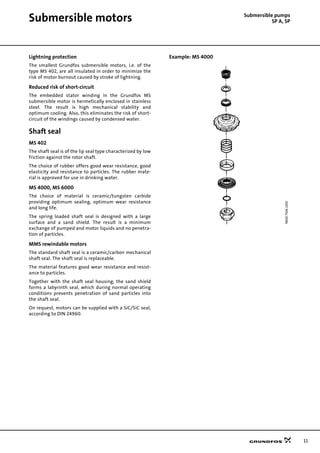
![14
Submersible pumps
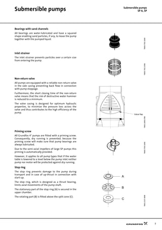
SP 1APerformance curves
TM0072714702PerformancecurvesTechnicaldataPowercurvesSP1A
0.0 0.2 0.4 0.6 0.8 1.0 1.2 1.4 Q [m³/h]
0.00
0.01
0.02
0.03
0.04
P2
[kW]
0
10
20
30
40
Eta
[%]
0.00
0.02
0.04
P2
[hp]
Eta
P2
0.0 0.2 0.4 0.6 0.8 1.0 1.2 1.4 Q [m³/h]
0
20
40
60
80
100
120
140
160
180
200
220
240
260
280
300
320
H
[m]
0
400
800
1200
1600
2000
2400
2800
p
[kPa]
0.0 0.1 0.2 0.3 0.4 Q [l/s]
SP 1A
ISO 9906 Annex A
50 Hz
-14
-18
-21
-28
-36
-42
-50
-57
-9](https://image.slidesharecdn.com/submersiblepump-grundfos-180406163941/85/Submersible-pump-GRUNDFOS-14-320.jpg)
![15
Technical data Submersible pumps
SP 1A
Dimensions and weights
TM0009551196
Pump type
Motor Dimensions [mm]
Net weight
[kg]
Type
Power
[kW]
C
B A
1x230V
3x230V
3x400V
1x230V
3x230V
3x400V
1x230V
3x230V
3x400V
SP 1A-9 MS 402 0.37 344 256 226 600 570 11 9
SP 1A-14 MS 402 0.37 449 256 226 705 675 12 10
SP 1A-18 MS 402 0.55 533 291 241 824 774 14 12
SP 1A-21 MS 402 0.55 596 291 241 887 837 14 12
SP 1A-28 MS 402 0.75 743 306 276 1049 1019 16 15
SP 1A-36 MS 402 1.1 956 346 306 1302 1262 25 23
SP 1A-42 MS 402 1.1 1082 346 306 1428 1388 27 25
SP 1A-50 MS 402 1.5 1250 346 346 1596 1596 30 29
SP 1A-57 MS 402 1.5 1397 346 346 1743 1743 32 32
101 mm = Maximum diameter of pump
inclusive of cable guard and motor.
A
BC
101
95
Rp 1 1/4](https://image.slidesharecdn.com/submersiblepump-grundfos-180406163941/85/Submersible-pump-GRUNDFOS-15-320.jpg)
![16
Submersible pumps
SP 2APerformance curves
TM0072724702SP2A
0.0 0.4 0.8 1.2 1.6 2.0 2.4 2.8 Q [m³/h]
0.00
0.01
0.02
0.03
0.04
0.05
P2
[kW]
0
10
20
30
40
50
Eta
[%]
0.00
0.02
0.04
0.06
[hp]
P2
Eta
P2
0.0 0.4 0.8 1.2 1.6 2.0 2.4 2.8 Q [m³/h]
0
40
80
120
160
200
240
280
320
360
400
440
480
520
560
H
[m]
0
800
1600
2400
3200
4000
4800
5600
p
[kPa]
0.0 0.2 0.4 0.6 0.8 Q [l/s]
SP 2A
ISO 9906 Annex A
50 Hz
-13
-18
-23
-28
-33
-40
-48
-55
-6
-65
-75
-9
-90](https://image.slidesharecdn.com/submersiblepump-grundfos-180406163941/85/Submersible-pump-GRUNDFOS-16-320.jpg)
![17
Technical data Submersible pumps
SP 2A
Dimensions and weights
TM0009551196
Pump type
Motor Dimensions [mm]
Net weight
[kg]
Type
Power
[kW]
C
B A
1x230V
3x230V
3x400V
1x230V
3x230V
3x400V
1x230V
3x230V
3x400V
SP 2A-6 MS 402 0.37 281 256 226 537 507 10 9
SP 2A-9 MS 402 0.37 344 256 226 600 570 11 9
SP 2A-13 MS 402 0.55 428 291 241 719 669 13 11
SP 2A-18 MS 402 0.75 533 306 276 839 809 15 13
SP 2A-23 MS 402 1.1 638 346 306 984 944 17 16
SP 2A-28 MS 402 1.5 743 346 346 1089 1089 19 18
SP 2A-33 MS 402 1.5 844 346 346 1190 1190 20 19
SP 2A-40 MS 4000 2.2 1040 573 1613 37
SP 2A-40 MS 402 2.2 1040 346 1386 27
SP 2A-48 MS 4000 2.2 1208 573 1781 39
SP 2A-48 MS 402 2.2 1208 346 1554 30
SP 2A-55 MS 4000 3.0 1355 493 1848 38
SP 2A-65 MS 4000 3.0 1565 493 2058 41
SP 2A-75 MS 4000 4.0 1954 573 2527 57
SP 2A-90 MS 4000 4.0 2269 573 2842 64
101 mm = Maximum diameter of pump
inclusive of cable guard and motor.
SP 2A-75 and SP 2A-90 are mounted in
sleeve for R 1¼ connection and with
max. diameter 108 mm.
A
BC
101
95
Rp 1 1/4](https://image.slidesharecdn.com/submersiblepump-grundfos-180406163941/85/Submersible-pump-GRUNDFOS-17-320.jpg)
![18
Submersible pumps
SP 3APerformance curves
TM0072734702SP3A
0.0 0.4 0.8 1.2 1.6 2.0 2.4 2.8 3.2 3.6 4.0 Q [m³/h]
0.00
0.03
0.06
0.09
0.12
P2
[kW]
0
15
30
45
60
Eta
[%]
0.00
0.04
0.08
0.12
0.16
P2
[hp]
Eta
P2
0.0 0.4 0.8 1.2 1.6 2.0 2.4 2.8 3.2 3.6 4.0 Q [m³/h]
0
40
80
120
160
200
240
280
320
360
H
[m]
0
400
800
1200
1600
2000
2400
2800
3200
3600
p
[kPa]
0.0 0.2 0.4 0.6 0.8 1.0 1.2 Q [l/s]
SP 3A
ISO 9906 Annex A
50 Hz
-12
-15
-18
-22
-25
-29
-33
-39
-45
-52
-6
-60
-9](https://image.slidesharecdn.com/submersiblepump-grundfos-180406163941/85/Submersible-pump-GRUNDFOS-18-320.jpg)
![19
Technical data Submersible pumps
SP 3A
Dimensions and weights
TM0009551196
Pump type
Motor Dimensions [mm]
Net weight
[kg]
Type
Power
[kW]
C
B A
1x230V
3x230V
3x400V
1x230V
3x230V
3x400V
1x230V
3x230V
3x400V
SP 3A-6 MS 402 0.37 281 256 226 537 507 10 9
SP 3A-6N MS 4000R 2.2 326 573 899 26
SP 3A-6N MS 4000R 0.75 326 398 724 18
SP 3A-9 MS 402 0.55 344 291 241 635 585 12 10
SP 3A-9N MS 4000R 2.2 389 573 962 27
SP 3A-9N MS 4000R 0.75 389 398 787 19
SP 3A-12 MS 402 0.75 407 306 276 713 683 13 12
SP 3A-12N MS 4000R 2.2 452 573 1025 28
SP 3A-12N MS 4000R 0.75 452 398 850 20
SP 3A-15 MS 402 1.1 470 346 306 816 776 16 14
SP 3A-15N MS 4000R 2.2 515 573 1088 29
SP 3A-15N MS 4000R 1.1 515 413 928 22
SP 3A-18 MS 402 1.1 533 346 306 879 839 16 15
SP 3A-18N MS 4000R 2.2 578 573 1151 30
SP 3A-18N MS 4000R 1.1 578 413 991 23
SP 3A-22 MS 402 1.5 617 346 346 963 963 18 17
SP 3A-22N MS 4000R 2.2 662 573 1235 31
101 mm = Maximum diameter of
pump inclusive of cable guard and
motor.
SP 3A-22N MS 4000R 1.5 662 413 1075 24
SP 3A-25 MS 402 1.5 680 346 346 1026 1026 18 18
SP 3A-25N MS 4000R 2.2 725 573 1298 32
SP 3A-25N MS 4000R 1.5 725 413 1138 25
SP 3A-29 MS 4000 2.2 764 573 1337 29
SP 3A-29 MS 402 2.2 764 346 1110 20
SP 3A-29N MS 4000R 2.2 809 573 453 1382 1262 33 28
SP 3A-33 MS 4000 2.2 848 573 1421 30
SP 3A-33 MS 402 2.2 848 346 1194 21
SP 3A-33N MS 4000R 2.2 893 573 453 1466 1346 34 29
SP 3A-39 MS 4000 3.0 1019 493 1512 32
SP 3A-39N MS 4000R 3.0 1019 493 1512 32
SP 3A-45 MS 4000 3.0 1145 493 1638 34
SP 3A-45N MS 4000R 3.0 1145 493 1638 34
SP 3A-52 MS 4000 4.0 1292 573 1865 41
SP 3A-52N MS 4000R 4.0 1292 573 1865 41
SP 3A-60 MS 4000 4.0 1460 573 2033 43
SP 3A-60N MS 4000R 4.0 1460 573 2033 43
A
BC
101
95
Rp 1 1/4](https://image.slidesharecdn.com/submersiblepump-grundfos-180406163941/85/Submersible-pump-GRUNDFOS-19-320.jpg)
![20
Submersible pumps
SP 5APerformance curves
TM0072744702SP5A
0.0 0.8 1.6 2.4 3.2 4.0 4.8 5.6 6.4Q [m³/h]
0.00
0.04
0.08
0.12
P2
[kW]
0
20
40
60
Eta
[%]
0.00
0.08
0.16
P2
[hp]
Eta
P2
0.0 0.8 1.6 2.4 3.2 4.0 4.8 5.6 6.4Q [m³/h]
0
40
80
120
160
200
240
280
320
360
400
440
480
520
560
H
[m]
0
800
1600
2400
3200
4000
4800
5600
p
[kPa]
0.0 0.4 0.8 1.2 1.6 Q [l/s]
SP 5A
ISO 9906 Annex A
50 Hz
-12
-17
-21
-25
-33
-38
-4
-44
-52
-6
-60
-75
-8
-85](https://image.slidesharecdn.com/submersiblepump-grundfos-180406163941/85/Submersible-pump-GRUNDFOS-20-320.jpg)
![21
Technical data Submersible pumps
SP 5A
Dimensions and weights
TM0009561196
Pump type
Motor Dimensions [mm]
Net weight
[kg]
Type
Power
[kW]
C
B A
D E
1x230V
3x230V
3x400V
1x230V
3x230V
3x400V
1x230V
3x230V
3x400V
SP 5A-4 MS 402 0.37 240 256 226 496 466 95 101 10 8
SP 5A-4N MS 4000R 2.2 284 573 857 95 101 25
SP 5A-4N MS 4000R 0.75 284 398 682 95 101 17
SP 5A-6 MS 402 0.55 282 291 241 573 523 95 101 11 10
SP 5A-6N MS 4000R 2.2 326 573 899 95 101 26
SP 5A-6N MS 4000R 0.75 326 398 724 95 101 18
SP 5A-8 MS 402 0.75 324 306 276 630 600 95 101 13 11
SP 5A-8N MS 4000R 2.2 368 573 941 95 101 27
SP 5A-8N MS 4000R 0.75 368 398 766 95 101 19
SP 5A-12 MS 402 1.1 408 346 306 754 714 95 101 15 13
SP 5A-12N MS 4000R 2.2 452 573 1025 95 101 28
SP 5A-12N MS 4000R 1.1 452 413 865 95 101 21
SP 5A-17 MS 402 1.5 513 346 346 859 859 95 101 17 16
SP 5A-17N MS 4000R 2.2 557 573 1130 95 101 29
SP 5A-17N MS 4000R 1.5 557 413 970 95 101 22
SP 5A-21 MS 4000 2.2 597 573 1170 95 101 27
SP 5A-75 and SP 5A-85 are mounted
in sleeve for R 1½ connection.
SP 5A-21 MS 402 2.2 597 346 943 95 101 18
SP 5A-21N MS 4000R 2.2 641 573 453 1214 1094 95 101 30 25
SP 5A-25 MS 4000 2.2 681 573 1254 95 101 28
SP 5A-25 MS 402 2.2 681 346 1027 95 101 19
SP 5A-25N MS 4000R 2.2 725 573 453 1298 1178 95 101 32 27
SP 5A-33 MS 4000 3.0 849 493 1342 95 101 26
SP 5A-33N MS 4000R 3.0 893 493 1386 95 101 30
SP 5A-38 MS 4000 4.0 998 573 1571 95 101 36
SP 5A-38N MS 4000R 4.0 998 573 1571 95 101 36
SP 5A-44 MS 4000 4.0 1124 573 1697 95 101 38
SP 5A-44N MS 4000R 4.0 1124 573 1697 95 101 38
SP 5A-52 MS 4000 5.5 1292 673 1965 95 101 46
SP 5A-52N MS 4000R 5.5 1292 673 1965 95 101 46
SP 5A-60 MS 4000 5.5 1460 673 2133 95 101 48
SP 5A-60N MS 4000R 5.5 1460 673 2133 95 101 48
SP 5A-52 MS 6000 5.5 1354 541 1895 138 138 60
SP 5A-52N MS 6000R 5.5 1354 541 1895 138 138 60
SP 5A-60 MS 6000 5.5 1522 541 2063 138 138 63
SP 5A-60N MS 6000R 5.5 1522 541 2063 138 138 63
SP 5A-75 MS 6000 7.5 2146 571 2717 138 140 86
SP 5A-85 MS 6000 7.5 2356 571 2927 138 140 92
E = Maximum diameter of pump inclusive of cable guard and motor.
A
BC
E
D
Rp 1 1/2](https://image.slidesharecdn.com/submersiblepump-grundfos-180406163941/85/Submersible-pump-GRUNDFOS-21-320.jpg)
![22
Submersible pumps
SP 8APerformance range
TM0072754702SP8A
0 1 2 3 4 5 6 7 8 9 10 Q [m³/h]
0.00
0.08
0.16
0.24
P2
[kW]
0
20
40
60
Eta
[%]
0.0
0.1
0.2
0.3
P2
[hp]
Eta
P2
0 1 2 3 4 5 6 7 8 9 10 Q [m³/h]
0
50
100
150
200
250
300
350
400
450
500
550
600
650
700
H
[m]
0
800
1600
2400
3200
4000
4800
5600
6400
p
[kPa]
0.0 0.5 1.0 1.5 2.0 2.5 3.0 Q [l/s]
SP 8A
ISO 9906 Annex A
50 Hz
-10
-100
-110
-12
-15
-18
-21
-25
-30
-37
-44
-5
-50
-58
-66
-7
-73
-82
-91](https://image.slidesharecdn.com/submersiblepump-grundfos-180406163941/85/Submersible-pump-GRUNDFOS-22-320.jpg)
![23
Technical data Submersible pumps
SP 8A
Dimensions and weights
TM0009571196
Pump type
Motor Dimensions [mm]
Net weight
[kg]
Type
Power
[kW]
C
B A
D E
1x230V
3x230V
3x400V
1x230V
3x230V
3x400V
1x230V
3x230V
3x400V
SP 8A-5 MS 402 0.75 409 306 276 715 685 95 101 15 13
SP 8A-5N (R) MS 4000R 2.2 409 573 982 95 101 27
SP 8A-5N (R) MS 4000R 0.75 409 398 807 95 101 19
SP 8A-7 MS 402 1.1 493 346 306 839 799 95 101 17 16
SP 8A-7N (R) MS 4000R 2.2 493 573 1066 95 101 28
SP 8A-7N (R) MS 4000R 1.1 493 413 906 95 101 21
SP 8A-10 MS 402 1.5 619 346 346 965 965 95 101 19 19
SP 8A-10N (R) MS 4000R 2.2 619 573 1192 95 101 30
SP 8A-10N (R) MS 4000R 1.5 619 413 1032 95 101 23
SP 8A-12 MS 4000 2.2 703 573 1276 95 101 30
SP 8A-12 MS 402 2.2 703 346 1049 95 101 21
SP 8A-12N (R) MS 4000R 2.2 703 573 453 1276 1156 95 101 30 25
SP 8A-15 MS 4000 2.2 829 573 1402 95 101 32
SP 8A-15 MS 402 2.2 829 346 1175 95 101 23
SP 8A-15N (R) MS 4000R 2.2 829 573 453 1402 1282 95 101 32 27
SP 8A-18 MS 4000 3.0 955 493 1448 95 101 29
SP 8A-18N (R) MS 4000R 3.0 955 493 1448 95 101 29
SP 8A-21 MS 4000 4.0 1081 573 1654 95 101 35
SP 8A-21N (R) MS 4000R 4.0 1081 573 1654 95 101 35
SP 8A-58(N) to SP 8A-110(N) are
mounted in sleeve for R 2 connection.
SP 8A-25 MS 4000 4.0 1249 573 1822 95 101 37
SP 8A-25N (R) MS 4000R 4.0 1249 573 1822 95 101 37
SP 8A-30 MS 4000 5.5 1459 673 2132 95 101 45
SP 8A-30N (R) MS 4000R 5.5 1459 673 2132 95 101 45
SP 8A-37 MS 4000 5.5 1753 673 2426 95 101 49
SP 8A-37N (R) MS 4000R 5.5 1753 673 2426 95 101 49
SP 8A-30 MS 6000 5.5 1521 541 2062 138 138 56
SP 8A-30N MS 6000R 5.5 1521 541 2062 138 138 56
SP 8A-37 MS 6000 5.5 1815 541 2356 138 138 60
SP 8A-37N MS 6000R 5.5 1815 541 2356 138 138 60
SP 8A-44 MS 4000 7.5 2051 773 2824 95 101 60
SP 8A-44N MS 4000 7.5 2051 773 2824 95 101 60
SP 8A-44 MS 6000 7.5 2109 571 2680 138 138 66
SP 8A-44N MS 6000R 7.5 2109 571 2680 138 138 66
SP 8A-50 MS 4000 7.5 2303 773 3076 95 101 64
SP 8A-50N MS 4000 7.5 2303 773 3076 95 101 64
SP 8A-50 MS 6000 7.5 2361 571 2932 138 138 70
SP 8A-50N MS 6000R 7.5 2361 571 2932 138 138 70
SP 8A-58 MS 6000 9.2 3013 601 3614 138 140 104
SP 8A-58N MS 6000R 9.2 3013 601 3614 138 140 104
SP 8A-66 MS 6000 11.0 3349 631 3980 138 140 114
SP 8A-66N MS 6000R 11.0 3349 631 3980 138 140 114
SP 8A-73 MS 6000 11.0 3643 631 4274 138 140 120
SP 8A-73N MS 6000R 11.0 3643 631 4274 138 140 120
SP 8A-82 MS 6000 13.0 4021 661 4682 138 140 131
SP 8A-82N MS 6000R 13.0 4021 661 4682 138 140 131
SP 8A-91 MS 6000 15.0 4399 696 5095 138 140 143
SP 8A-91N MS 6000R 15.0 4399 696 5095 138 140 143
SP 8A-100 MS 6000 15.0 4777 696 5473 138 140 150
SP 8A-100N MS 6000R 15.0 4777 696 5473 138 140 150
SP 8A-110 MS 6000 18.5 5197 751 5948 138 140 164
SP 8A-110N MS 6000R 18.5 5197 751 5948 138 140 164
E = Maximum diameter of pump inclusive of cable guard and motor.
A
BC
E
Rp 2
D](https://image.slidesharecdn.com/submersiblepump-grundfos-180406163941/85/Submersible-pump-GRUNDFOS-23-320.jpg)
![24
Submersible pumps
SP 14APerformance curves
TM0072764702SP14A
0 2 4 6 8 10 12 14 16 18 Q [m³/h]
0.0
0.1
0.2
0.3
P2
[kW]
0
20
40
60
Eta
[%]
0.0
0.2
0.4
P2
[hp]
Eta
P2
0 2 4 6 8 10 12 14 16 18 Q [m³/h]
0
10
20
30
40
50
60
70
80
90
100
110
120
130
140
150
160
170
H
[m]
0
200
400
600
800
1000
1200
1400
1600
p
[kPa]
0 1 2 3 4 5 Q [l/s]
SP 14A
ISO 9906 Annex A
50 Hz
-10
-13
-18
-25
-5
-7](https://image.slidesharecdn.com/submersiblepump-grundfos-180406163941/85/Submersible-pump-GRUNDFOS-24-320.jpg)
![25
Technical data Submersible pumps
SP 14A
Dimensions and weights
TM0009571196
Pump type
Motor Dimensions [mm] Net weight
[kg]
Type
Power
[kW]
C
B A
D E
1x230V
3x230V
3x400V
1x230
V
3x230V
3x400V
1x230V
3x230V
3x400V
SP 14A-5 MS 402 1.5 510 346 346 856 856 95 101 18 17
SP 14A-7 MS 4000 2.2 640 573 1213 95 101 29
SP 14A-7 MS 402 2.2 640 346 986 95 101 19
SP 14A-10 MS 4000 3.0 835 493 1328 95 101 27
SP 14A-13 MS 4000 4.0 1030 573 1603 95 101 33
SP 14A-18 MS 4000 5.5 1355 673 2028 95 101 41
SP 14A-25 MS 4000 7.5 1810 773 2584 95 101 67
SP 14A-18 MS 6000 5.5 1417 541 1958 138 138 52
SP 14A-25 MS 6000 7.5 1872 571 2443 138 138 60
E = Maximum diameter of pump inclusive of cable guard and motor.
A
BC
E
Rp 2
D](https://image.slidesharecdn.com/submersiblepump-grundfos-180406163941/85/Submersible-pump-GRUNDFOS-25-320.jpg)
![26
Submersible pumps
SP 17Performance curves
TM0187574702SP17
0 2 4 6 8 10 12 14 16 18 20 Q [m³/h]
0
10
20
30
40
50
60
70
80
90
100
110
120
130
140
150
160
170
180
190
H
[m]
0 1 2 3 4 5 6 Q [l/s]
0
200
400
600
800
1000
1200
1400
1600
1800
p
[kPa]
SP 17
50 Hz
ISO 9906 Annex A
-1
-10
-11
-12
-13
-14
-15
-16
-17
-2
-3
-4
-5
-6
-7
-8
-9
0 2 4 6 8 10 12 14 16 18 20 Q [m³/h]
0
2
4
6
8
[m]
H
0
20
40
60
80
[%]
Eta
0
20
40
60
80
[kPa]
p
NPSH
Eta](https://image.slidesharecdn.com/submersiblepump-grundfos-180406163941/85/Submersible-pump-GRUNDFOS-26-320.jpg)
![27
Performance curves Submersible pumps
SP 17
TM0187584702
0 2 4 6 8 10 12 14 16 18 20 Q [m³/h]
50
100
150
200
250
300
350
400
450
500
550
600
650
H
[m]
0 1 2 3 4 5 6 Q [l/s]
800
1600
2400
3200
4000
4800
5600
6400
p
[kPa]
SP 17
50 Hz
ISO 9906 Annex A
-51
-53
-55
-58
-60
-18
-19
-20
-21
-22
-23
-24
-25
-26
-27
-28
-29
-30
-31
-32
-33
-34
-35
-36
-37
-38
-39
-40
-43
-45
-48
0 2 4 6 8 10 12 14 16 18 20 Q [m³/h]
0
2
4
6
8
[m]
H
0
20
40
60
80
[%]
Eta
0
20
40
60
80
[kPa]
p
NPSH
Eta](https://image.slidesharecdn.com/submersiblepump-grundfos-180406163941/85/Submersible-pump-GRUNDFOS-27-320.jpg)
![28
Technical data Submersible pumps
SP 17
Dimensions and weights
TM0124351798
Pump type
Motor Dimensions [mm]
Net weight
[kg]
Type
Power
[kW]
C
B A
D E* E**
1x230V
3x230V
3x400V
1x230V
3x230V
3x400V
1x230V
3x230V
3x400V
SP 17-1 MS 402 0.55 314 291 241 605 555 95 131 13 11
SP 17-1 N (R) MS 4000 R 0.75 314 398 712 95 131 17
SP 17-1 N (R) MS 4000 R 2.2 314 573 887 95 131 26
SP 17-2 MS 402 1.1 374 346 306 720 680 95 131 17 15
SP 17-2 N (R) MS 4000 R 1.1 374 413 787 95 131 20
SP 17-2 N (R) MS 4000 R 2.2 374 573 947 95 131 27
SP 17-3 MS 402 2.2 435 346 781 95 131 19
SP 17-3 N (R) MS 4000 R 2.2 435 573 453 1008 888 95 131 28 23
SP 17-4 MS 402 2.2 495 346 841 95 131 20
SP 17-4 MS 4000 2.2 495 573 453 1068 948 95 131 29 24
SP 17-5 MS 4000 3.0 556 494 1050 95 131 26
SP 17-6 MS 4000 4.0 616 574 1190 95 131 31
SP 17-7 MS 4000 4.0 677 574 1251 95 131 33
SP 17-8 MS 4000 5.5 737 674 1411 95 131 39
SP 17-9 MS 4000 5.5 798 674 1472 95 131 40
SP 17-10 MS 4000 5.5 858 674 1532 95 131 41
SP 17-11 MS 4000 7.5 919 773 1692 95 131 47
SP 17-12 MS 4000 7.5 979 773 1752 95 131 49
SP 17-13 MS 4000 7.5 1040 773 1813 95 131 50
SP 17-43 to SP 17-60 are mounted in
sleeve for R 3 connection.
SP 17-8 MS 6000 5.5 753 544 1297 138 142 142 50
SP 17-9 MS 6000 5.5 814 544 1358 138 142 142 51
SP 17-10 MS 6000 5.5 874 544 1418 138 142 142 53
SP 17-11 MS 6000 7.5 935 574 1509 138 142 142 55
SP 17-12 MS 6000 7.5 995 574 1569 138 142 142 56
SP 17-13 MS 6000 7.5 1056 574 1630 138 142 142 57
SP 17-14 MS 6000 9.2 1116 604 1720 138 142 142 64
SP 17-15 MS 6000 9.2 1177 604 1781 138 142 142 65
SP 17-16 MS 6000 9.2 1237 604 1841 138 142 142 66
SP 17-17 MS 6000 9.2 1298 604 1902 138 142 142 67
SP 17-18 MS 6000 11 1358 634 1992 138 142 142 72
SP 17-19 MS 6000 11 1419 634 2053 138 142 142 73
SP 17-20 MS 6000 11 1479 634 2113 138 142 142 74
SP 17-21 MS 6000 13 1540 664 2204 138 142 142 78
SP 17-22 MS 6000 13 1600 664 2264 138 142 142 79
SP 17-23 MS 6000 13 1661 664 2325 138 142 142 81
SP 17-24 MS 6000 13 1721 664 2385 138 142 142 82
SP 17-25 MS 6000 15 1782 699 2481 138 142 142 87
SP 17-26 MS 6000 15 1842 699 2541 138 142 142 88
SP 17-27 MS 6000 15 1903 699 2602 138 142 142 89
SP 17-28 MS 6000 18.5 1963 754 2717 138 142 142 96
SP 17-29 MS 6000 18.5 2024 754 2778 138 142 142 97
SP 17-30 MS 6000 18.5 2084 754 2838 138 142 142 99
SP 17-31 MS 6000 18.5 2145 754 2899 138 142 142 100
SP 17-32 MS 6000 18.5 2205 754 2959 138 142 142 101
SP 17-33 MS 6000 18.5 2266 754 3020 138 142 142 102
SP 17-34 MS 6000 22 2326 814 3140 138 142 142 109
SP 17-35 MS 6000 22 2387 814 3201 138 142 142 111
SP 17-36 MS 6000 22 2447 814 3261 138 142 142 112
SP 17-37 MS 6000 22 2508 814 3322 138 142 142 113
SP 17-38 MS 6000 22 2568 814 3382 138 142 142 114
SP 17-39 MS 6000 22 2629 814 3443 138 142 142 115
SP 17-40 MS 6000 22 2689 814 3503 138 142 142 117
SP 17-43 MS 6000 26 3118 874 3992 138 175 181 164
SP 17-45 MS 6000 26 3239 874 4113 138 175 181 167
SP 17-48 MS 6000 26 3420 874 4294 138 175 181 172
SP 17-51 MS 6000 30 3602 944 4546 138 175 181 185
SP 17-53 MS 6000 30 3723 944 4667 138 175 181 189
SP 17-55 MMS 6000 37 3844 1425 5269 144 175 181 239
SP 17-58 MMS 6000 37 4025 1425 5450 144 175 181 244
SP 17-60 MMS 6000 37 4146 1425 5571 144 175 181 248
* Maximum diameter of pump with one motor cable.
** Maximum diameter of pump with two motor cables.
The pump types above are also available in R and N-versions, see page 5 for further details.
Dimensions as above.
Other types of connection are possible by means of connecting pieces, see page 86.
Rp 2 1/2
A
BC
D
E](https://image.slidesharecdn.com/submersiblepump-grundfos-180406163941/85/Submersible-pump-GRUNDFOS-28-320.jpg)
![29
Power curves Submersible pumps
SP 17
TM0187594702
0 2 4 6 8 10 12 14 16 18 20 Q [m³/h]
0.0
0.4
0.8
1.2
1.6
2.0
2.4
2.8
3.2
3.6
4.0
4.4
4.8
5.2
5.6
6.0
6.4
6.8
7.2
7.6
8.0
8.4
8.8
9.2
9.6
10.0
[kW]
P2
0 1 2 3 4 5 6 Q [l/s]
0
1
2
3
4
5
6
7
8
9
10
11
12
13
[hp]
P2
SP 17
50 Hz
ISO 9906 Annex A
-17
-16
-15
-14
-13
-12
-11
-10
-9
-8
-7
-6
-5
-4
-3
-2
-1](https://image.slidesharecdn.com/submersiblepump-grundfos-180406163941/85/Submersible-pump-GRUNDFOS-29-320.jpg)
![30
Power curves Submersible pumps
SP 17
TM0187604702
0 2 4 6 8 10 12 14 16 18 20 Q [m³/h]
5
6
7
8
9
10
11
12
13
14
15
16
17
18
19
20
21
22
23
24
25
26
27
28
29
30
31
32
33
34
35
36
[kW]
P2
0 1 2 3 4 5 6 Q [l/s]
8
10
12
14
16
18
20
22
24
26
28
30
32
34
36
38
40
42
44
46
48
50
[hp]
P2
SP 17
50 Hz
ISO 9906 Annex A
-51
-53
-55
-58
-60
-48
-45
-43
-40
-39
-38
-37
-36
-35
-34
-33
-32
-31
-30
-29
-28
-27
-25
-18
-19
-20
-21
-22
-23
-24
-26](https://image.slidesharecdn.com/submersiblepump-grundfos-180406163941/85/Submersible-pump-GRUNDFOS-30-320.jpg)
![31
Submersible pumps
SP 30Performance curves
TM0187614702SP30
0 4 8 12 16 20 24 28 32 36 Q [m³/h]
0
10
20
30
40
50
60
70
80
90
100
110
120
130
140
150
160
170
H
[m]
0 2 4 6 8 10 Q [l/s]
0
200
400
600
800
1000
1200
1400
1600
p
[kPa]
SP 30
50 Hz
ISO 9906 Annex A
-1
-10
-11
-12
-13
-14
-15
-2
-3
-4
-5
-6
-7
-8
-9
0 4 8 12 16 20 24 28 32 36 Q [m³/h]
0
2
4
6
8
[m]
H
0
20
40
60
80
[%]
Eta
0
20
40
60
80
[kPa]
p
NPSH
Eta](https://image.slidesharecdn.com/submersiblepump-grundfos-180406163941/85/Submersible-pump-GRUNDFOS-31-320.jpg)
![32
Performance curves Submersible pumps
SP 30
TM0187624702
0 4 8 12 16 20 24 28 32 36 Q [m³/h]
50
100
150
200
250
300
350
400
450
500
550
600
650
H
[m]
0 2 4 6 8 10 Q [l/s]
800
1200
1600
2000
2400
2800
3200
3600
4000
4400
4800
5200
5600
6000
6400
p
[kPa]
SP 30
50 Hz
ISO 9906 Annex A
-52
-54
-16
-17
-18
-19
-20
-21
-22
-23
-24
-25
-26
-27
-28
-29
-30
-31
-32
-33
-34
-35
-39
-43
-46
-49
0 4 8 12 16 20 24 28 32 36 Q [m³/h]
0
2
4
6
8
[m]
H
0
20
40
60
80
[%]
Eta
0
20
40
60
80
[kPa]
p
NPSH
Eta](https://image.slidesharecdn.com/submersiblepump-grundfos-180406163941/85/Submersible-pump-GRUNDFOS-32-320.jpg)
![33
Technical data Submersible pumps
SP 30
Dimensions and weights
TM0009601196
Pump type
Motor Dimensions [mm]
Net weight
[kg]
Type
Power
[kW]
C
B A
D E* E**
1x230V
3x230V
3x400V
1x230V
3x230V
3x400V
1x230V
3x230V
3x400V
SP 30-1 MS 402 1.1 349 346 306 695 655 95 131 16 14
SP 30-1 N (R) MS 4000 R 2.2 349 573 922 95 131 26
SP 30-2 MS 402 2.2 445 346 791 95 131 19
SP 30-2 N (R) MS 4000 R 2.2 445 573 453 1018 898 95 131 28 23
SP 30-3 MS 4000 3.0 541 494 1035 95 131 25
SP 30-4 MS 4000 4.0 637 574 1211 95 131 31
SP 30-5 MS 4000 5.5 733 674 1407 95 131 38
SP 30-6 MS 4000 5.5 829 674 1503 95 131 39
SP 30-7 MS 4000 7.5 925 773 1698 95 131 46
SP 30-8 MS 4000 7.5 1021 773 1794 95 131 48
SP 30-5 MS 6000 5.5 749 544 1293 138 142 142 49
SP 30-6 MS 6000 5.5 845 544 1389 138 142 142 51
SP 30-7 MS 6000 7.5 941 574 1515 138 142 142 53
SP 30-8 MS 6000 7.5 1037 574 1611 138 142 142 55
SP 30-9 MS 6000 9.2 1133 604 1737 138 142 142 62
SP 30-10 MS 6000 9.2 1229 604 1833 138 142 142 64
SP 30-11 MS 6000 9.2 1325 604 1929 138 142 142 65
SP 30-39 to SP 30-54 are mounted in
sleeve for R 3 connection.
SP 30-12 MS 6000 11 1421 634 2055 138 142 142 70
SP 30-13 MS 6000 11 1517 634 2151 138 142 142 72
SP 30-14 MS 6000 13 1613 664 2277 138 142 142 76
SP 30-15 MS 6000 13 1709 664 2373 138 142 142 78
SP 30-16 MS 6000 15 1805 699 2504 138 142 142 84
SP 30-17 MS 6000 15 1901 699 2600 138 142 142 85
SP 30-18 MS 6000 18.5 1997 754 2751 138 142 142 93
SP 30-19 MS 6000 18.5 2093 754 2847 138 142 142 94
SP 30-20 MS 6000 18.5 2189 754 2943 138 142 142 96
SP 30-21 MS 6000 18.5 2285 754 3039 138 142 142 98
SP 30-22 MS 6000 22 2381 814 3195 138 142 142 105
SP 30-23 MS 6000 22 2477 814 3291 138 142 142 107
SP 30-24 MS 6000 22 2573 814 3387 138 142 142 109
SP 30-25 MS 6000 22 2669 814 3483 138 142 142 110
SP 30-26 MS 6000 22 2765 814 3579 138 142 142 112
SP 30-27 MS 6000 26 2861 874 3735 138 142 142 119
SP 30-28 MS 6000 26 2957 874 3831 138 142 142 121
SP 30-29 MS 6000 26 3053 874 3927 138 142 142 123
SP 30-30 MS 6000 26 3149 874 4023 138 142 142 124
SP 30-31 MS 6000 26 3245 874 4119 138 142 142 126
SP 30-32 MS 6000 30 3341 944 4285 138 144 145 136
SP 30-33 MS 6000 30 3437 944 4381 138 144 145 137
SP 30-34 MS 6000 30 3533 944 4477 138 144 145 139
SP 30-35 MS 6000 30 3629 944 4573 138 144 145 141
SP 30-39 MMS 6000 37 4260 1425 5685 144 175 181 253
SP 30-43 MMS 6000 37 4644 1425 6069 144 175 181 264
SP 30-46 MMS 8000 45 4881 1270 6151 192 175 181 325
SP 30-49 MMS 8000 45 5169 1270 6439 192 175 181 332
SP 30-52 MMS 8000 55 5457 1350 6807 192 192 192 357
SP 30-54 MMS 8000 55 5649 1350 6999 192 192 192 362
* Maximum diameter of pump with one motor cable.
** Maximum diameter of pump with two motor cables.
The pump types above are also available in R and N-versions, see page 5.
Dimensions as above.
Other types of connection are possible by means of connecting pieces, see page 86.
A
BC
E
D
Rp 3](https://image.slidesharecdn.com/submersiblepump-grundfos-180406163941/85/Submersible-pump-GRUNDFOS-33-320.jpg)
![34
Power curves Submersible pumps
SP 30
TM0187634702
0 4 8 12 16 20 24 28 32 36 Q [m³/h]
0.0
0.8
1.6
2.4
3.2
4.0
4.8
5.6
6.4
7.2
8.0
8.8
9.6
10.4
11.2
12.0
12.8
13.6
[kW]
P2
0 2 4 6 8 10 Q [l/s]
0
2
4
6
8
10
12
14
16
18
[hp]
P2
SP 30
50 Hz
ISO 9906 Annex A
-15
-14
-13
-12
-11
-10
-9
-8
-7
-6
-5
-4
-3
-2
-1](https://image.slidesharecdn.com/submersiblepump-grundfos-180406163941/85/Submersible-pump-GRUNDFOS-34-320.jpg)
![35
Power curves Submersible pumps
SP 30
TM0187644702
0 4 8 12 16 20 24 28 32 36 Q [m³/h]
6
8
10
12
14
16
18
20
22
24
26
28
30
32
34
36
38
40
42
44
46
48
50
52
[kW]
P2
0 2 4 6 8 10 Q [l/s]
12
16
20
24
28
32
36
40
44
48
52
56
60
64
68
[hp]
P2
SP 30
50 Hz
ISO 9906 Annex A
-52
-54
-49
-46
-43
-39
-35
-34
-33
-32
-31
-30
-29
-28
-16
-17
-18
-19
-20
-21
-22
-23
-24
-25
-26
-27](https://image.slidesharecdn.com/submersiblepump-grundfos-180406163941/85/Submersible-pump-GRUNDFOS-35-320.jpg)
![36
Submersible pumps
SP 46Performance curves
TM0187654702SP46
0 10 20 30 40 50 60 Q [m³/h]
0
20
40
60
80
100
120
140
160
180
200
H
[m]
0 5 10 15 Q [l/s]
0
400
800
1200
1600
2000
p
[kPa]
SP 46
50 Hz
ISO 9906 Annex A
-15
-14
-13
-12
-11
-10
-9
-9-C
-8
-8-C
-7
-6
-5
-4
-4-C
-3
-3-C
-2
-1
-1-B
-2-BB
0 10 20 30 40 50 60 Q [m³/h]
0
2
4
6
8
[m]
H
0
20
40
60
80
[%]
Eta
0
20
40
60
80
[kPa]
p
NPSH
Eta](https://image.slidesharecdn.com/submersiblepump-grundfos-180406163941/85/Submersible-pump-GRUNDFOS-36-320.jpg)
![37
Performance curves Submersible pumps
SP 46
TM0187664702
0 10 20 30 40 50 60 Q [m³/h]
40
80
120
160
200
240
280
320
360
400
440
480
520
H
[m]
0 5 10 15 Q [l/s]
800
1600
2400
3200
4000
4800
p
[kPa]
SP 46
50 Hz
ISO 9906 Annex A
-35
-37
-33
-30
-28
-26
-24
-23
-22
-21
-20
-19
-18
-17
-16
0 10 20 30 40 50 60 Q [m³/h]
0
2
4
6
8
[m]
H
0
20
40
60
80
[%]
Eta
0
20
40
60
80
[kPa]
p
NPSH
Eta](https://image.slidesharecdn.com/submersiblepump-grundfos-180406163941/85/Submersible-pump-GRUNDFOS-37-320.jpg)
![38
Technical data Submersible pumps
SP 46
Dimensions and weights
TM0009611196
Pump
type
Motor Dimensions [mm] Net
weight
[kg]Type
Power
[kW]
Rp 3 connection Rp 4 connection
B D
A C E* E** A C E* E**
SP 46-1-B MS 4000 1.1 777 364 141 783 370 145 413 95 20
SP 46-1 MS 4000 2.2 817 364 141 823 370 145 453 95 22
SP 46-2-BB MS 4000 2.2 930 477 141 936 483 145 453 95 24
SP 46-2 MS 4000 3.0 970 477 141 976 483 145 493 95 25
SP 46-3-C MS 4000 4.0 1163 590 141 1169 596 145 573 95 32
SP 46-3 MS 4000 5.5 1263 590 141 1269 596 145 673 95 37
SP 46-4-C MS 4000 5.5 1376 703 141 1382 709 145 673 95 39
SP 46-4 MS 4000 7.5 1476 703 141 1482 709 145 773 95 44
SP 46-5 MS 4000 7.5 1589 816 141 1595 822 145 773 95 47
SP 46-3 MS 6000 5.5 1150 606 145 150 1156 612 147 152 544 138 48
SP 46-4 MS 6000 7.5 1293 719 145 150 1299 725 147 152 574 138 52
SP 46-5 MS 6000 7.5 1406 832 145 150 1412 838 147 152 574 138 54
SP 46-6 MS 6000 9.2 1549 945 145 150 1555 951 147 152 604 138 62
SP 46-7 MS 6000 11 1692 1058 145 150 1698 1064 147 152 634 138 68
SP 46-8-C MS 6000 11 1805 1171 145 150 1811 1177 147 152 634 138 70
SP 46-8 MS 6000 13 1835 1171 145 150 1841 1177 147 152 664 138 73
SP 46-9-C MS 6000 13 1948 1284 145 150 1954 1290 147 152 664 138 76
SP 46-9 MS 6000 15 1983 1284 145 150 1989 1290 147 152 699 138 80
SP 46-10 MS 6000 15 2096 1397 145 150 2102 1403 147 152 699 138 82
SP 46-11 MS 6000 18.5 2264 1510 145 150 2270 1516 147 152 754 138 90
SP 46-26 to SP 46-37 are mounted
in sleeve for R 4 connection.
SP 46-12 MS 6000 18.5 2377 1623 145 150 2383 1629 147 152 754 138 93
SP 46-13 MS 6000 22 2550 1736 145 150 2556 1742 147 152 814 138 101
SP 46-14 MS 6000 22 2663 1849 145 150 2669 1855 147 152 814 138 104
SP 46-15 MS 6000 22 2776 1962 145 150 2782 1968 147 152 814 138 106
SP 46-16 MS 6000 26 2949 2075 145 150 2955 2081 147 152 874 138 114
SP 46-17 MS 6000 26 3062 2188 145 150 3068 2194 147 152 874 138 117
SP 46-18 MS 6000 30 3245 2301 145 150 3251 2307 147 152 944 138 128
SP 46-19 MS 6000 30 3358 2414 145 150 3364 2420 147 152 944 138 130
SP 46-20 MS 6000 30 3551 2607 145 150 3557 2613 147 152 944 138 132
SP 46-21 MMS 6000 37 4145 2720 145 150 4151 2726 147 152 1425 144 185
SP 46-22 MMS 6000 37 4258 2833 145 150 4264 2839 147 152 1425 144 188
SP 46-23 MMS 6000 37 4371 2946 145 150 4377 2952 147 152 1425 144 190
SP 46-24 MMS 6000 37 4484 3059 145 150 4490 3065 147 152 1425 144 193
SP 46-26 MMS 8000 45 4673 3403 192 192 1270 192 278
SP 46-28 MMS 8000 45 4899 3629 192 192 1270 192 284
SP 46-30 MMS 8000 45 5125 3855 192 192 1270 192 290
SP 46-33 MMS 8000 55 5544 4194 192 192 1350 192 314
SP 46-35 MMS 8000 55 5770 4420 192 192 1350 192 319
SP 46-37 MMS 8000 63 6136 4646 192 192 1490 192 351
* Maximum diameter of pump with one motor cable.
** Maximum diameter of pump with two motor cables.
The pump types above are also available in R and N-versions, see page 5.
Dimensions as above.
Other types of connection are possible by means of connecting pieces, see page 86.
A
BC
E
D
Rp 3
Rp 4](https://image.slidesharecdn.com/submersiblepump-grundfos-180406163941/85/Submersible-pump-GRUNDFOS-38-320.jpg)
![39
Power curves Submersible pumps
SP 46
TM0187674702
0 10 20 30 40 50 60 Q [m³/h]
0
2
4
6
8
10
12
14
16
18
20
22
[kW]
P2
0 5 10 15 Q [l/s]
0
4
8
12
16
20
24
28
[hp]
P2
SP 46
50 Hz
ISO 9906 Annex A
-15
-14
-13
-12
-11
-10
-9
-9-C
-8
-8-C
-7
-6
-5
-4
-4-C
-3
-3-C
-2
-2-BB
-1
-1-B](https://image.slidesharecdn.com/submersiblepump-grundfos-180406163941/85/Submersible-pump-GRUNDFOS-39-320.jpg)
![40
Power curves Submersible pumps
SP 46
TM0187684702
0 10 20 30 40 50 60 Q [m³/h]
14
16
18
20
22
24
26
28
30
32
34
36
38
40
42
44
46
48
50
52
54
56
58
[kW]
P2
0 5 10 15 Q [l/s]
20
25
30
35
40
45
50
55
60
65
70
75
[hp]
P2
SP 46
50 Hz
ISO 9906 Annex A
-35
-37
-33
-30
-28
-26
-24
-23
-22
-21
-20
-19
-18
-17
-16](https://image.slidesharecdn.com/submersiblepump-grundfos-180406163941/85/Submersible-pump-GRUNDFOS-40-320.jpg)
![41
Submersible pumps
SP 60Performance curves
TM0188264702SP60
0 10 20 30 40 50 60 70 80Q [m³/h]
0
10
20
30
40
50
60
70
80
90
100
110
120
130
140
H
[m]
0 5 10 15 20 Q [l/s]
0
200
400
600
800
1000
1200
1400
p
[kPa]
SP 60
50 Hz
ISO 9906 Annex A
-10
-9
-9-B
-8
-8-B
-7
-6
-5
-4
-3
-2
-2-B
-1
-1-A
0 10 20 30 40 50 60 70 80Q [m³/h]
0
2
4
6
8
[m]
H
0
20
40
60
80
[%]
Eta
0
20
40
60
80
[kPa]
p
NPSH
Eta](https://image.slidesharecdn.com/submersiblepump-grundfos-180406163941/85/Submersible-pump-GRUNDFOS-41-320.jpg)
![42
Performance curves Submersible pumps
SP 60
TM0188274702
0 10 20 30 40 50 60 70 80Q [m³/h]
40
60
80
100
120
140
160
180
200
220
240
260
280
300
320
340
360
380
400
420
440
H
[m]
0 5 10 15 20 Q [l/s]
400
800
1200
1600
2000
2400
2800
3200
3600
4000
p
[kPa]
SP 60
50 Hz
ISO 9906 Annex A
-24
-26
-28
-30
-22
-21
-20
-19
-18
-17
-16
-15
-14
-13
-12
-11
0 10 20 30 40 50 60 70 80Q [m³/h]
0
2
4
6
8
[m]
H
0
20
40
60
80
[%]
Eta
0
20
40
60
80
[kPa]
p
NPSH
Eta](https://image.slidesharecdn.com/submersiblepump-grundfos-180406163941/85/Submersible-pump-GRUNDFOS-42-320.jpg)
![43
Technical data Submersible pumps
SP 60
Dimensions and weights
TM0009611196
Pump
type
Motor Dimensions [mm] Net
weight
[kg]Type
Power
[kW]
Rp 3 connection Rp 4 connection
B D
A C E* E** A C E* E**
SP 60-1-A MS 4000 1.5 780 364 142 786 370 146 416 95 20
SP 60-1 MS 4000 2.2 817 364 142 823 370 146 453 95 22
SP 60-2-B MS 4000 3.0 970 477 142 976 483 146 493 95 25
SP 60-2 MS 4000 4.0 1050 477 142 1056 483 146 573 95 29
SP 60-3 MS 4000 5.5 1263 590 142 1269 596 146 673 95 37
SP 60-3 MS 6000 5.5 1150 606 147 150 1156 612 149 152 544 138 47
SP 60-4 MS 4000 7.5 1476 703 142 1482 709 146 773 95 44
SP 60-4 MS 6000 7.5 1293 719 147 150 1299 725 149 152 574 138 50
SP 60-5 MS 6000 9.2 1436 832 147 150 1442 838 149 152 604 138 60
SP 60-6 MS 6000 11 1584 950 147 150 1585 951 149 152 634 138 65
SP 60-7 MS 6000 13 1722 1058 147 150 1728 1064 149 152 664 138 71
SP 60-8-B MS 6000 13 1835 1171 147 150 1841 1177 149 152 664 138 73
SP 60-8 MS 6000 15 1870 1171 147 150 1876 1177 149 152 699 138 77
SP 60-9-B MS 6000 15 1983 1284 147 150 1989 1290 149 152 699 138 80
SP 60-9 MS 6000 18.5 2038 1284 147 150 2044 1290 149 152 754 138 85
SP 60-10 MS 6000 18.5 2151 1397 147 150 2157 1403 149 152 754 138 88
SP 60-11 MS 6000 22 2324 1510 147 150 2330 1516 149 152 814 138 96
SP 60-12 MS 6000 22 2437 1623 147 150 2443 1629 149 152 814 138 99
SP 60-13 MS 6000 26 2610 1736 147 150 2616 1742 149 152 874 138 107
SP 60-14 MS 6000 26 2723 1849 147 150 2729 1855 149 152 874 138 109
SP 60-15 MS 6000 26 2836 1962 147 150 2842 1968 149 152 874 138 112
SP 60-16 MS 6000 30 3019 2075 147 150 3025 2081 149 152 944 138 122
SP 60-17 MS 6000 30 3132 2188 147 150 3138 2194 152 156 944 138 125
SP 60-18 MMS 6000 37 3806 2381 150 154 3812 2387 152 156 1425 144 178
SP 60-19 MMS 6000 37 3919 2494 150 154 3925 2500 152 156 1425 144 180
SP 60-20 MMS 6000 37 4032 2607 150 154 4038 2613 152 156 1425 144 183
SP 60-21 MMS 6000 37 4147 2722 150 154 4151 2726 152 156 1425 144 185
SP 60-22 MMS 8000 45 4054 2784 180 180 4058 2788 180 180 1270 192 239
SP 60-24 MMS 8000 45 4447 3177 193 195 1270 192 272
SP 60-26 MMS 8000 55 4753 3403 193 195 1350 192 293
SP 60-28 MMS 8000 55 4979 3629 193 195 1350 192 299
SP 60-30 MMS 8000 55 5205 3855 193 195 1350 192 305
* Maximum diameter of pump with one motor cable.
** Maximum diameter of pump with two motor cables.
The pump types above are also available in R and N-versions, see page 5 for further details.
Dimensions as above.
Other types of connection are possible by means of connecting pieces, see page 86.
A
BC
E
D
Rp 3
Rp 4](https://image.slidesharecdn.com/submersiblepump-grundfos-180406163941/85/Submersible-pump-GRUNDFOS-43-320.jpg)
![44
Power curves Submersible pumps
SP 60
TM0188284702
0 10 20 30 40 50 60 70 80Q [m³/h]
0
1
2
3
4
5
6
7
8
9
10
11
12
13
14
15
16
17
18
[kW]
P2
0 5 10 15 20 Q [l/s]
0
4
8
12
16
20
24
[hp]
P2
SP 60
50 Hz
ISO 9906 Annex A
-10
-9
-9-B
-8
-8-B
-7
-6
-5
-4
-3
-2
-2-B
-1
-1-A](https://image.slidesharecdn.com/submersiblepump-grundfos-180406163941/85/Submersible-pump-GRUNDFOS-44-320.jpg)
![45
Power curves Submersible pumps
SP 60
TM0188294702
0 10 20 30 40 50 60 70 80Q [m³/h]
14
16
18
20
22
24
26
28
30
32
34
36
38
40
42
44
46
48
50
52
54
[kW]
P2
0 5 10 15 20 Q [l/s]
20
24
28
32
36
40
44
48
52
56
60
64
68
72
[hp]
P2
SP 60
50 Hz
ISO 9906 Annex A
-24
-26
-28
-30
-22
-21
-20
-19
-18
-17
-16
-15
-14
-13
-12
-11](https://image.slidesharecdn.com/submersiblepump-grundfos-180406163941/85/Submersible-pump-GRUNDFOS-45-320.jpg)
![46
Submersible pumps
SP 77Performance curves
TM0187694702SP77
0 10 20 30 40 50 60 70 80 90 Q [m³/h]
0
10
20
30
40
50
60
70
80
90
100
110
120
130
140
150
160
170
180
H
[m]
0 5 10 15 20 25 Q [l/s]
0
200
400
600
800
1000
1200
1400
1600
p
[kPa]
SP 77
50 Hz
ISO 9906 Annex A
-9
-8
-8-B
-7
-6
-5
-4
-4-B
-3
-3-B
-2
-2-B
-1
0 10 20 30 40 50 60 70 80 90 Q [m³/h]
0
2
4
6
8
[m]
H
0
20
40
60
80
[%]
Eta
0
20
40
60
80
[kPa]
p
NPSH
Eta](https://image.slidesharecdn.com/submersiblepump-grundfos-180406163941/85/Submersible-pump-GRUNDFOS-46-320.jpg)
![47
Performance curves Submersible pumps
SP 77
TM0187704702
0 10 20 30 40 50 60 70 80 90 Q [m³/h]
60
80
100
120
140
160
180
200
220
240
260
280
300
320
340
360
380
400
420
440
H
[m]
0 5 10 15 20 25 Q [l/s]
800
1200
1600
2000
2400
2800
3200
3600
4000
p
[kPa]
SP 77
50 Hz
ISO 9906 Annex A
-21
-22
-20
-19
-18
-17
-16
-15
-14
-13
-12
-11
-10
0 10 20 30 40 50 60 70 80 90 Q [m³/h]
0
2
4
6
8
[m]
H
0
20
40
60
80
[%]
Eta
0
20
40
60
80
[kPa]
p
NPSH
Eta](https://image.slidesharecdn.com/submersiblepump-grundfos-180406163941/85/Submersible-pump-GRUNDFOS-47-320.jpg)
![48
Technical data Submersible pumps
SP 77
Dimensions and weights
TM0078722196
Pump
type
Motor Dimensions [mm] Net
weight
[kg]Type
Power
[kW]
Rp 5 connection 5" Grundfos flange
B D
A C E* E** A C E* E**
SP 77-1 MS 6000 5.5 1162 618 178 186 1162 618 200 200 544 138 55
SP 77-2-B MS 6000 5.5 1290 746 178 186 1290 746 200 200 544 138 59
SP 77-2 MS 6000 7.5 1320 746 178 186 1320 746 200 200 574 138 63
SP 77-3-B MS 6000 9.2 1478 874 178 186 1478 874 200 200 604 138 72
SP 77-3 MS 6000 11 1508 874 178 186 1508 874 200 200 634 138 75
SP 77-4-B MS 6000 13 1667 1003 178 186 1667 1003 200 200 664 138 82
SP 77-4 MS 6000 15 1702 1003 178 186 1702 1003 200 200 699 138 86
SP 77-5 MS 6000 18.5 1885 1131 178 186 1885 1131 200 200 754 138 95
SP 77-6 MS 6000 22 2073 1259 178 186 2073 1259 200 200 814 138 105
SP 77-7 MS 6000 26 2261 1387 178 186 2261 1387 200 200 874 138 114
SP 77-8-B MS 6000 26 2389 1515 178 186 2389 1515 200 200 874 138 118
SP 77-8 MS 6000 30 2459 1515 178 186 2459 1515 200 200 944 138 126
SP 77-9 MS 6000 30 2587 1643 178 186 2587 1643 200 200 944 138 129
SP 77-10 MMS 6000 37 3196 1771 178 186 3196 1771 200 200 1425 144 181
SP 77-11 MMS 6000 37 3339 1914 178 186 3323 1898 200 200 1425 144 184
SP 77-12 MMS 8000 45 3313 2043 200 204 3313 2043 209 209 1270 192 240
SP 77-13 MMS 8000 55 3522 2172 200 204 3522 2172 209 209 1350 192 259
SP 77-14 MMS 8000 55 3650 2300 200 204 3650 2300 209 209 1350 192 263
SP 77-15 MMS 8000 55 3779 2429 200 204 1350 192 266
SP 77-16 MMS 8000 63 4047 2557 200 204 1490 192 296
SP 77-17 MMS 8000 63 4175 2685 200 204 1490 192 300
TM0073231798
SP 77-18 MMS 8000 63 4304 2814 200 204 1490 192 304
SP 77-19 MMS 8000 75 4826 3236 200 204 1590 192 334
SP 77-20 MMS 8000 75 4954 3364 200 204 1590 192 338
SP 77-21 MMS 8000 75 5082 3492 200 202 1590 192 342
SP 77-22 MMS 8000 92 5450 3620 200 202 1830 192 391
* Maximum diameter of pump with one motor cable.
** Maximum diameter of pump with two motor cables.
The pump types are also available in N-version, see page 5 for further details.
Dimensions as above.
Other types of connection are possible by means of connecting pieces, see page 86.
A
BC
E
D
Rp 5
8 x ø15
ø125
ø175
ø200](https://image.slidesharecdn.com/submersiblepump-grundfos-180406163941/85/Submersible-pump-GRUNDFOS-48-320.jpg)
![49
Power curves Submersible pumps
SP 77
TM0187714702
0 10 20 30 40 50 60 70 80 90 Q [m³/h]
0
2
4
6
8
10
12
14
16
18
20
22
24
26
28
30
32
[kW]
P2
0 5 10 15 20 25 Q [l/s]
0
5
10
15
20
25
30
35
40
[hp]
P2
SP 77
50 Hz
ISO 9906 Annex A
-9
-8
-8-B
-7
-6
-5
-4
-4-B
-3
-3-B
-2
-2-B
-1](https://image.slidesharecdn.com/submersiblepump-grundfos-180406163941/85/Submersible-pump-GRUNDFOS-49-320.jpg)
![50
Power curves Submersible pumps
SP 77
TM0187724702
0 10 20 30 40 50 60 70 80 90 Q [m³/h]
20
24
28
32
36
40
44
48
52
56
60
64
68
72
76
80
[kW]
P2
0 5 10 15 20 25 Q [l/s]
30
40
50
60
70
80
90
100
110
[hp]
P2
SP 77
50 Hz
ISO 9906 Annex A
-21
-22
-20
-19
-18
-17
-16
-15
-14
-13
-12
-11
-10](https://image.slidesharecdn.com/submersiblepump-grundfos-180406163941/85/Submersible-pump-GRUNDFOS-50-320.jpg)
![51
Submersible pumps
SP 95Performance curves
TM0187734702SP95
0 20 40 60 80 100 120 Q [m³/h]
0
20
40
60
80
100
120
140
160
180
H
[m]
0 10 20 30 Q [l/s]
0
400
800
1200
1600
p
[kPa]
SP 95
50 Hz
ISO 9906 Annex A
-9
-8
-7
-6
-5
-5-AB
-4
-4-B
-3
-3-B
-3-BB
-2
-2-A
-2-BB
-1
0 20 40 60 80 100 120 Q [m³/h]
0
2
4
6
8
[m]
H
0
20
40
60
80
[%]
Eta
0
20
40
60
80
[kPa]
p
NPSH
Eta](https://image.slidesharecdn.com/submersiblepump-grundfos-180406163941/85/Submersible-pump-GRUNDFOS-51-320.jpg)
![52
Performance curves Submersible pumps
SP 95
TM0187744702
0 20 40 60 80 100 120 Q [m³/h]
40
80
120
160
200
240
280
320
360
400
H
[m]
0 10 20 30 Q [l/s]
800
1600
2400
3200
4000
p
[kPa]
SP 95
50 Hz
ISO 9906 Annex A
-20
-19
-18
-17
-16
-15
-14
-13
-12
-11
-10
0 20 40 60 80 100 120 Q [m³/h]
0
2
4
6
8
[m]
H
0
20
40
60
80
[%]
Eta
0
20
40
60
80
[kPa]
p
NPSH
Eta](https://image.slidesharecdn.com/submersiblepump-grundfos-180406163941/85/Submersible-pump-GRUNDFOS-52-320.jpg)
![53
Technical data Submersible pumps
SP 95
Dimensions and weights
TM0078722196
Pump
type
Motor Dimensions [mm] Net
weight
[kg]Type
Power
[kW]
Rp 5 connection 5" Grundfos flange
B D
A C E* E** A C E* E**
SP 95-1 MS 6000 5.5 1162 618 178 186 1162 618 200 200 544 138 55
SP 95-2-BB MS 6000 5.5 1290 746 178 186 1290 746 200 200 544 138 72
SP 95-2-A MS 6000 7.5 1320 746 178 186 1320 746 200 200 574 138 63
SP 95-2 MS 6000 9.2 1350 746 178 186 1350 746 200 200 604 138 68
SP 95-3-BB MS 6000 9.2 1478 874 178 186 1478 874 200 200 604 138 72
SP 95-3-B MS 6000 11 1508 874 178 186 1508 874 200 200 634 138 75
SP 95-3 MS 6000 13 1538 874 178 186 1538 874 200 200 664 138 78
SP 95-4-B MS 6000 15 1702 1003 178 186 1702 1003 200 200 699 138 86
SP 95-4 MS 6000 18.5 1757 1003 178 186 1757 1003 200 200 754 138 91
SP 95-5-AB MS 6000 18.5 1885 1131 178 186 1885 1131 200 200 754 138 95
SP 95-5 MS 6000 22 1945 1131 178 186 1945 1131 200 200 814 138 101
SP 95-6 MS 6000 26 2133 1259 178 186 2133 1259 200 200 874 138 110
SP 95-7 MS 6000 30 2331 1387 178 186 2331 1387 200 200 944 138 122
SP 95-8 MMS 6000 37 2940 1515 178 186 2940 1515 200 200 1425 144 173
SP 95-9 MMS 6000 37 3067 1642 178 186 3067 1642 200 200 1425 144 177
SP 95-10 MMS 8000 45 3055 1785 196 204 3055 1785 205 205 1270 192 233
SP 95-11 MMS 8000 55 3264 1914 196 204 3264 1914 205 205 1350 192 251
SP 95-12 MMS 8000 55 3393 2043 196 204 3393 2043 205 205 1350 192 255
SP 95-13 MMS 8000 55 3522 2172 196 204 3522 2172 205 205 1350 192 259
SP 95-14 MMS 8000 63 3790 2300 196 204 3790 2300 205 205 1490 192 289
SP 95-15 MMS 8000 75 4019 2429 196 204 1590 192 311
TM0073231798
SP 95-16 MMS 8000 75 4147 2557 196 204 1590 192 315
SP 95-17 MMS 8000 75 4275 2685 196 204 1590 192 319
SP 95-18 MMS 8000 92 4938 3108 196 204 1830 192 376
SP 95-19 MMS 8000 92 5066 3236 196 204 1830 192 380
SP 95-20 MMS 8000 92 5194 3364 196 204 1830 192 384
* Maximum diameter of pump with one motor cable.
** Maximum diameter of pump with two motor cables.
The pump types above are also available in N-version, see page 5 for further details.
Dimensions as above.
Other types of connection are possible by means of connecting pieces, see page 86.
A
BC
E
D
Rp 5
8 x ø15
ø125
ø175
ø200](https://image.slidesharecdn.com/submersiblepump-grundfos-180406163941/85/Submersible-pump-GRUNDFOS-53-320.jpg)
![54
Power curves Submersible pumps
SP 95
TM0187754702
0 20 40 60 80 100 120 Q [m³/h]
0
4
8
12
16
20
24
28
32
36
40
[kW]
P2
0 10 20 30 Q [l/s]
0
10
20
30
40
50
[hp]
P2
SP 95
50 Hz
ISO 9906 Annex A
-9
-8
-7
-6
-5
-5-AB
-4
-4-B
-3
-3-B
-3-BB
-2
-2-A
-2-BB
-1](https://image.slidesharecdn.com/submersiblepump-grundfos-180406163941/85/Submersible-pump-GRUNDFOS-54-320.jpg)
![55
Power curves Submersible pumps
SP 95
TM0187764702
0 20 40 60 80 100 120 Q [m³/h]
28
32
36
40
44
48
52
56
60
64
68
72
76
80
84
88
[kW]
P2
0 10 20 30 Q [l/s]
40
50
60
70
80
90
100
110
120
[hp]
P2
SP 95
50 Hz
ISO 9906 Annex A
-20
-19
-18
-17
-16
-15
-14
-13
-12
-11
-10](https://image.slidesharecdn.com/submersiblepump-grundfos-180406163941/85/Submersible-pump-GRUNDFOS-55-320.jpg)
![56
+
Submersible pumps
SP 125Performance curves
TM0187774702SP125
0 20 40 60 80 100 120 140 Q [m³/h]
0
10
20
30
40
50
60
70
80
90
100
110
120
130
140
150
160
170
H
[m]
0 10 20 30 40 Q [l/s]
0
200
400
600
800
1000
1200
1400
1600
p
[kPa]
SP 125
50 Hz
ISO 9906 Annex A
-6-A
-6-AA
-5
-5-A
-5-AA
-4
-4-A
-4-AA
-3
-3-A
-3-AA
-2
-2-A
-2-AA
-1
-1-A
0 20 40 60 80 100 120 140 160Q [m³/h]
0
2
4
6
8
[m]
H
0
20
40
60
80
[%]
Eta
0
20
40
60
80
[kPa]
p
NPSH
Eta](https://image.slidesharecdn.com/submersiblepump-grundfos-180406163941/85/Submersible-pump-GRUNDFOS-56-320.jpg)
![57
Performance curves Submersible pumps
SP 125
TM0187784702
0 20 40 60 80 100 120 140 160Q [m³/h]
60
80
100
120
140
160
180
200
220
240
260
280
300
320
340
360
380
400
420
440
460
480
500
H
[m]
0 10 20 30 40 Q [l/s]
800
1200
1600
2000
2400
2800
3200
3600
4000
4400
4800
p
[kPa]
SP 125
50 Hz
ISO 9906 Annex A
-11
-12
-13
-14
-15
-16
-17
-10
-10-A
-10-AA
-9
-9-A
-9-AA
-8
-8-A
-8-AA
-7
-7-A
-7-AA
-6
0 20 40 60 80 100 120 140 160Q [m³/h]
0
2
4
6
8
[m]
H
0
20
40
60
80
[%]
Eta
0
20
40
60
80
[kPa]
p
NPSH
Eta](https://image.slidesharecdn.com/submersiblepump-grundfos-180406163941/85/Submersible-pump-GRUNDFOS-57-320.jpg)
![58
Technical data Submersible pumps
SP 125
Dimensions and weights
TM0087603596
Pump
type
Motor Dimensions [mm] Net
weight
[kg]Type
Power
[kW]
Rp 6 connection 6" Grundfos flange
B D
A C E* E** A C E* E**
SP 125-1-A MS 6000 7.5 1225 651 211 218 1225 651 222 226 574 138 70
SP 125-1 MS 6000 11 1285 651 211 218 1285 651 222 226 634 138 79
SP 125-2-AA MS 6000 13 1471 807 211 218 1471 807 222 226 664 138 88
SP 125-2-A MS 6000 18.5 1561 807 211 218 1561 807 222 226 754 138 97
SP 125-2 MS 6000 22 1621 807 211 218 1621 807 222 226 814 138 103
SP 125-3-AA MS 6000 22 1777 963 211 218 1777 963 222 226 814 138 109
SP 125-3-A MS 6000 26 1837 963 211 218 1837 963 222 226 874 138 115
SP 125-3 MS 6000 30 1907 963 211 218 1907 963 222 226 944 138 123
SP 125-4-AA MMS 6000 37 2544 1119 211 218 2544 1119 222 226 1425 144 176
SP 125-4-A MMS 6000 37 2544 1119 211 218 2544 1119 222 226 1425 144 176
SP 125-4 MMS 6000 37 2544 1119 211 218 2544 1119 222 226 1425 144 176
SP 125-5-AA MMS 8000 45 2545 1275 213 218 2545 1275 223 226 1270 192 236
SP 125-5-A MMS 8000 45 2545 1275 213 218 2545 1275 223 226 1270 192 236
SP 125-5 MMS 8000 55 2625 1275 213 218 2625 1245 223 226 1350 192 251
SP 125-6-AA MMS 8000 55 2781 1431 213 218 2781 1431 223 226 1350 192 257
SP 125-6-A MMS 8000 55 2781 1431 213 218 2781 1431 223 226 1350 192 257
SP 125-6 MMS 8000 63 2921 1431 218 227 2921 1431 229 232 1490 192 283
SP 125-7-AA MMS 8000 63 3077 1587 218 227 3077 1587 229 232 1490 192 289
SP 125-7-A MMS 8000 63 3077 1587 218 227 3077 1587 229 232 1490 192 289
SP 125-7 MMS 8000 75 3177 1587 218 227 3177 1587 229 232 1590 192 308
SP 125-8-AA MMS 8000 75 3333 1743 218 227 1590 192 314
TM0073241798
SP 125-8-A MMS 8000 75 3333 1743 218 227 1590 192 314
SP 125-8 MMS 8000 75 3333 1743 218 227 1590 192 314
SP 125-9-AA MMS 8000 92 3729 1899 218 227 1830 192 366
SP 125-9-A MMS 8000 92 3729 1899 218 227 1830 192 366
SP 125-9 MMS 8000 92 3729 1899 218 227 1830 192 366
SP 125-10-AA MMS 8000 92 3885 2055 218 227 1830 192 372
SP 125-10-A MMS 8000 92 3885 2055 218 227 1830 192 372
SP 125-10 MMS 8000 92 3885 2055 218 227 1830 192 372
SP 125-11 MMS 8000 110 4567 2507 218 227 2060 192 438
SP 125-12 MMS 10000 132 4584 2714 237 237 1870 237 556
SP 125-13 MMS 10000 132 4740 2870 237 237 1870 237 562
SP 125-14 MMS 10000 147 5095 3025 237 237 2070 237 633
SP 125-15 MMS 10000 147 5251 3181 237 237 2070 237 639
SP 125-16 MMS 10000 170 5556 3336 237 237 2220 237 685
SP 125-17 MMS 10000 170 5712 3492 237 237 2220 237 691
* Maximum diameter of pump with one motor cable.
** Maximum diameter of pump with two motor cables.
The pump types above are also available in R and N-versions, see page 5 for further details.
Dimensions as above.
Other types of connection are possible by means of connecting pieces, see page 86.
A
BC
E
D
Rp 6
8 x ø15
ø170
ø196
ø220](https://image.slidesharecdn.com/submersiblepump-grundfos-180406163941/85/Submersible-pump-GRUNDFOS-58-320.jpg)
![59
Power curves Submersible pumps
SP 125
TM0187794702
0 20 40 60 80 100 120 140 Q [m³/h]
0
4
8
12
16
20
24
28
32
36
40
44
48
52
56
[kW]
P2
0 10 20 30 40 Q [l/s]
0
10
20
30
40
50
60
70
[hp]
P2
SP 125
50 Hz
ISO 9906 Annex A
-6-A
-6-AA
-5
-5-A
-5-AA
-4
-4-A
-4-AA
-3
-3-A
-3-AA
-2
-2-A
-2-AA
-1
-1-A](https://image.slidesharecdn.com/submersiblepump-grundfos-180406163941/85/Submersible-pump-GRUNDFOS-59-320.jpg)
![60
Power curves Submersible pumps
SP 125
TM0187804702
0 20 40 60 80 100 120 140 Q [m³/h]
30
40
50
60
70
80
90
100
110
120
130
140
150
160
170
[kW]
P2
0 10 20 30 40 Q [l/s]
60
80
100
120
140
160
180
200
220
[hp]
P2
SP 125
50 Hz
ISO 9906 Annex A
-11
-12
-13
-14
-15
-16
-17
-10
-10-A
-10-AA
-9
-9-A
-9-AA
-8
-8-A
-8-AA
-7
-7-A
-7-AA
-6](https://image.slidesharecdn.com/submersiblepump-grundfos-180406163941/85/Submersible-pump-GRUNDFOS-60-320.jpg)
![61
Submersible pumps
SP 160Performance curves
TM0187814702SP160
0 20 40 60 80 100 120 140 160 180 200 Q [m³/h]
0
10
20
30
40
50
60
70
80
90
100
110
120
130
140
150
H
[m]
0 10 20 30 40 50 60 Q [l/s]
0
200
400
600
800
1000
1200
1400
p
[kPa]
SP 160
50 Hz
ISO 9906 Annex A
-5-A
-5-AA
-4
-4-A
-4-AA
-3
-3-A
-3-AA
-2
-2-A
-2-AA
-1
-1-A
0 20 40 60 80 100 120 140 160 180 200 Q [m³/h]
0
4
8
12
16
[m]
H
0
20
40
60
80
[%]
Eta
0
40
80
120
160
[kPa]
p
NPSH
Eta](https://image.slidesharecdn.com/submersiblepump-grundfos-180406163941/85/Submersible-pump-GRUNDFOS-61-320.jpg)
![62
Performance curves Submersible pumps
SP 160
TM0087824702
0 20 40 60 80 100 120 140 160 180 200 Q [m³/h]
40
60
80
100
120
140
160
180
200
220
240
260
280
300
320
340
360
380
400
420
440
460
H
[m]
0 10 20 30 40 50 60 Q [l/s]
400
800
1200
1600
2000
2400
2800
3200
3600
4000
4400
p
[kPa]
SP 160
50 Hz
ISO 9906 Annex A
-15
-10
-10-A
-10-AA
-11
-12
-13
-14
-9
-9-A
-9-AA
-8
-8-A
-8-AA
-7
-7-A
-7-AA
-6
-6-A
-6-AA
-5
0 20 40 60 80 100 120 140 160 180 200 Q [m³/h]
0
4
8
12
16
[m]
H
0
20
40
60
80
[%]
Eta
0
40
80
120
160
[kPa]
p
NPSH
Eta](https://image.slidesharecdn.com/submersiblepump-grundfos-180406163941/85/Submersible-pump-GRUNDFOS-62-320.jpg)
![63
Technical data Submersible pumps
SP 160
Dimensions and weights
TM0087603596
Pump
type
Motor Dimensions [mm] Net
weight
[kg]Type
Power
[kW]
Rp 6 connection 6" Grundfos flange
B D
A C E* E** A C E* E**
SP 160-1-A MS 6000 9.2 1255 651 211 218 1255 651 222 226 604 138 76
SP 160-1 MS 6000 13 1315 651 211 218 1315 651 222 226 664 138 82
SP 160-2-AA MS 6000 18.5 1561 807 211 218 1561 807 222 226 754 138 97
SP 160-2-A MS 6000 22 1621 807 211 218 1621 807 222 226 814 138 103
SP 160-2 MS 6000 26 1681 807 211 218 1681 807 222 226 874 138 109
SP 160-3-AA MS 6000 30 1907 963 211 218 1907 963 222 226 944 138 123
SP 160-3-A MMS 6000 37 2388 963 211 218 2388 963 222 226 1425 144 170
SP 160-3 MMS 6000 37 2388 963 211 218 2388 963 222 226 1425 144 170
SP 160-4-AA MMS 8000 45 2389 1119 218 227 2389 1119 229 232 1270 192 230
SP 160-4-A MMS 8000 45 2389 1119 218 227 2389 1119 229 232 1270 192 230
SP 160-4 MMS 8000 55 2469 1119 218 227 2469 1119 229 232 1350 192 245
SP 160-5-AA MMS 8000 55 2625 1275 218 227 2625 1275 229 232 1350 192 251
SP 160-5-A MMS 8000 55 2625 1275 218 227 2625 1275 229 232 1350 192 251
SP 160-5 MMS 8000 63 2765 1275 218 227 2765 1275 229 232 1490 192 277
SP 160-6-AA MMS 8000 63 2921 1431 218 227 2921 1431 229 232 1490 192 283
SP 160-6-A MMS 8000 75 3021 1431 218 227 3021 1431 229 232 1590 192 302
SP 160-6 MMS 8000 75 3021 1431 218 227 3021 1431 229 232 1590 192 302
SP 160-7-AA MMS 8000 75 3177 1587 218 227 1590 192 302
SP 160-7-A MMS 8000 92 3417 1587 218 227 1830 192 354
SP 160-7 MMS 8000 92 3417 1587 218 227 1830 192 354
SP 160-8-AA MMS 8000 92 3573 1743 218 227 1830 192 360
TM0073241798
SP 160-8-A MMS 8000 92 3573 1743 218 227 1830 192 360
SP 160-8 MMS 8000 92 3573 1743 218 227 1830 192 360
SP 160-9-AA MMS 8000 110 3959 1899 218 227 2060 192 416
SP 160-9-A MMS 8000 110 3959 1899 218 227 2060 192 416
SP 160-9 MMS 8000 110 3959 1899 218 227 2060 192 416
SP 160-10-AA MMS 8000 110 4411 2351 218 227 2060 192 432
SP 160-10-A MMS 10000 132 4273 2403 237 237 1870 237 544
SP 160-10 MMS 10000 132 4273 2403 237 237 1870 237 544
SP 160-11 MMS 10000 132 4429 2559 237 237 1870 237 550
SP 160-12 MMS 10000 147 4784 2714 237 237 2070 237 621
SP 160-13 MMS 10000 170 5090 2870 237 237 2220 237 667
SP 160-14 MMS 10000 170 5245 3025 237 237 2220 237 673
SP 160-15 MMS 12000 190 5239 3259 286 286 1980 286 803
* Maximum diameter of pump with one motor cable.
** Maximum diameter of pump with two motor cables.
The pump types above are also available in N-version, see page 5 for further details.
Dimensions as above.
Other types of connection are possible by means of connecting pieces, see page 86.
A
BC
E
D
Rp 6
8 x ø15
ø170
ø196
ø220](https://image.slidesharecdn.com/submersiblepump-grundfos-180406163941/85/Submersible-pump-GRUNDFOS-63-320.jpg)
![64
Power curves Submersible pumps
SP 160
TM0087834702
0 20 40 60 80 100 120 140 160 180 200 Q [m³/h]
0
4
8
12
16
20
24
28
32
36
40
44
48
52
56
60
[kW]
P2
0 10 20 30 40 50 60 Q [l/s]
0
10
20
30
40
50
60
70
80
[hp]
P2
SP 160
50 Hz
ISO 9906 Annex A
-5-A
-5-AA
-4
-4-A
-4-AA
-3
-3-A
-3-AA
-2
-2-A
-2-AA
-1
-1-A](https://image.slidesharecdn.com/submersiblepump-grundfos-180406163941/85/Submersible-pump-GRUNDFOS-64-320.jpg)
![65
Power curves Submersible pumps
SP 160
TM0087844702
0 20 40 60 80 100 120 140 160 180 200 Q [m³/h]
40
44
48
52
56
60
64
68
72
76
80
84
88
92
96
100
104
108
112
116
120
124
128
132
136
140
144
148
152
156
160
164
168
172
176
180
184
[kW]
P2
0 10 20 30 40 50 60 Q [l/s]
60
70
80
90
100
110
120
130
140
150
160
170
180
190
200
210
220
230
240
250
[hp]
P2
SP 160
50 Hz
ISO 9906 Annex A
-15
-10-AA
-10-A
-10
-11
-12
-13
-14
-9
-9-A
-9-AA
-8
-8-A
-8-AA
-7
-7-A
-7-AA
-6
-6-A
-6-AA
-5](https://image.slidesharecdn.com/submersiblepump-grundfos-180406163941/85/Submersible-pump-GRUNDFOS-65-320.jpg)
![66
Submersible pumps
SP 215Performance curves
TM0087854702SP215
0 25 50 75 100 125 150 175 200 225 250 275 Q [m³/h]
0
20
40
60
80
100
120
140
160
180
200
220
240
H
[m]
0 20 40 60 80 Q [l/s]
0
400
800
1200
1600
2000
2400
p
[kPa]
SP 215
50 Hz
ISO 9906 Annex A
-6
-6-A
-6-AA
-5
-5-A
-5-AA
-4
-4-A
-4-AA
-3
-3-A
-3-AA
-2
-2-A
-2-AA
-1
-1-A
0 40 80 120 160 200 240 280 Q [m³/h]
0
4
8
12
16
[m]
H
0
20
40
60
80
[%]
Eta
0
40
80
120
160
[kPa]
p
NPSH
Eta](https://image.slidesharecdn.com/submersiblepump-grundfos-180406163941/85/Submersible-pump-GRUNDFOS-66-320.jpg)
![67
Performance curves Submersible pumps
SP 215
TM0087864702
0 40 80 120 160 200 240 280 Q [m³/h]
80
100
120
140
160
180
200
220
240
260
280
300
320
340
360
380
400
420
440
H
[m]
0 20 40 60 80 Q [l/s]
800
1200
1600
2000
2400
2800
3200
3600
4000
p
[kPa]
SP 215
50 Hz
ISO 9906 Annex A
-11
-10
-10-A
-10-AA
-9
-9-A
-9-AA
-8
-8-A
-8-AA
-7
-7-A
-7-AA
0 40 80 120 160 200 240 280 Q [m³/h]
0
4
8
12
16
[m]
H
0
20
40
60
80
[%]
Eta
0
40
80
120
160
[kPa]
p
NPSH
Eta](https://image.slidesharecdn.com/submersiblepump-grundfos-180406163941/85/Submersible-pump-GRUNDFOS-67-320.jpg)
![68
Technical data Submersible pumps
SP 215
Dimensions and weights
TM0087603596
Pump
type
Motor Dimensions [mm] Net
weight
[kg]Type
Power
[kW]
Rp 6 connection 6" Grundfos flange
B D
A C E* E** A C E* E**
SP 215-1-A MS 6000 15 1489 790 241 247 1489 790 241 247 699 138 92
SP 215-1 MS 6000 18.5 1544 790 241 247 1544 790 241 247 754 138 97
SP 215-2-AA MS 6000 30 1910 966 241 247 1910 966 241 247 944 138 127
SP 215-2-A MMS 6000 37 2391 966 241 247 2391 966 241 247 1425 144 174
SP 215-2 MMS 8000 45 2236 966 241 247 2236 966 241 247 1270 192 228
SP 215-3-AA MMS 8000 55 2492 1142 241 247 2492 1142 241 247 1350 192 253
SP 215-3-A MMS 8000 55 2492 1142 241 247 2492 1142 241 247 1350 192 253
SP 215-3 MMS 8000 63 2632 1142 241 247 2632 1142 241 247 1490 192 279
SP 215-4-AA MMS 8000 75 2908 1318 241 247 2908 1318 241 247 1590 192 308
SP 215-4-A MMS 8000 75 2908 1318 241 247 2908 1318 241 247 1590 192 308
SP 215-4 MMS 8000 75 2908 1318 241 247 2908 1318 241 247 1590 192 308
SP 215-5-AA MMS 8000 92 3324 1494 241 247 3324 1494 241 247 1830 192 364
SP 215-5-A MMS 8000 92 3324 1494 241 247 3324 1494 241 247 1830 192 364
SP 215-5 MMS 8000 92 3554 1494 241 247 3554 1494 241 247 1830 192 364
SP 215-6-AA MMS 8000 110 3730 1670 241 247 3730 1670 241 247 2060 192 424
SP 215-6-A MMS 8000 110 3730 1670 241 247 3730 1670 241 247 2060 192 424
SP 215-6 MMS 8000 110 3730 1670 241 247 3730 1670 241 247 2060 192 424
SP 215-7-AA MMS 10000 132 4016 2146 241 247 1870 237 547
SP 215-7-A MMS 10000 132 4016 2146 241 247 1870 237 547
SP 215-7 MMS 10000 132 4016 2146 241 247 1870 237 547
SP 215-8-AA MMS 10000 147 4392 2322 241 247 2070 237 622
TM0073241798
SP 215-8-A MMS 10000 147 4392 2322 241 247 2070 237 622
SP 215-8 MMS 10000 147 4392 2322 241 247 2070 237 622
SP 215-9-AA MMS 10000 170 4718 2498 276 276 2220 237 672
SP 215-9-A MMS 10000 170 4718 2498 276 276 2220 237 672
SP 215-9 MMS 10000 170 4718 2498 276 276 2220 237 672
SP 215-10-AA MMS 12000 190 4654 2674 276 276 1980 286 793
SP 215-10-A MMS 12000 190 4654 2674 276 276 1980 286 793
SP 215-10 MMS 12000 190 4654 2674 276 276 1980 286 793
SP 215-11 MMS 12000 220 4990 2850 286 286 2140 286 853
* Maximum diameter of pump with one motor cable.
** Maximum diameter of pump with two motor cables.
The pump types above are also available in N-version, see page 5 for further details.
Dimensions as above.
Other types of connection are possible by means of connecting pieces, see page 86.
A
BC
E
D
Rp 6
8 x ø15
ø170
ø196
ø220](https://image.slidesharecdn.com/submersiblepump-grundfos-180406163941/85/Submersible-pump-GRUNDFOS-68-320.jpg)
![69
Power curves Submersible pumps
SP 215
TM0087874702
0 40 80 120 160 200 240 280 Q [m³/h]
0
8
16
24
32
40
48
56
64
72
80
88
96
104
112
[kW]
P2
0 20 40 60 80 Q [l/s]
0
20
40
60
80
100
120
140
[hp]
P2
SP 215
50 Hz
ISO 9906 Annex A
-6
-6-A
-6-AA
-5
-5-A
-5-AA
-4
-4-A
-4-AA
-3
-3-A
-3-AA
-2
-2-A
-2-AA
-1
-1-A](https://image.slidesharecdn.com/submersiblepump-grundfos-180406163941/85/Submersible-pump-GRUNDFOS-69-320.jpg)
![70
Power curves Submersible pumps
SP 215
TM0087884702
0 40 80 120 160 200 240 280 Q [m³/h]
80
88
96
104
112
120
128
136
144
152
160
168
176
184
192
200
208
[kW]
P2
0 20 40 60 80 Q [l/s]
120
140
160
180
200
220
240
260
280
[hp]
P2
SP 215
50 Hz
ISO 9906 Annex A
-11
-10
-10-A
-10-AA
-9
-9-A
-9-AA
-8
-8-A
-8-AA
-7
-7-A
-7-AA](https://image.slidesharecdn.com/submersiblepump-grundfos-180406163941/85/Submersible-pump-GRUNDFOS-70-320.jpg)
![71
Submersible motors
SP A, SPTechnical data
1 x 230 V, submersible motors
3 x 230 V, submersible motors
Electrical data Dimensions
Motor Full load
current
In [A]
Motor efficiency [%] Power factor
Control box for
3-wire motors
Capacitor for
PSC motors
Length
[mm]
Weight
[kg]Type Size
Power
[kW]
η50% η75% η100%
Cos ϕ
50%
Cos ϕ
75%
Cos ϕ
100%
MS 402 4" 0.37 3.95 48.0 54.0 57.0 0.58 0.68 0.77 3.4* SA-SPM2 16µF, 400V, 50Hz 256 6.8
MS 402 4" 0.55 5.80 49.5 56.5 59.5 0.52 0.65 0.74 3.5* SA-SPM2 20µF, 400V, 50Hz 291 8.2
MS 402 4" 0.75 7.45 52.0 58.0 60.0 0.57 0.69 0.79 3.6* SA-SPM2 30µF, 400V, 50Hz 306 8.9
MS 402 4" 1.1 7.30 62.0 69.5 72.5 0.99 0.99 0.99 4.3* SA-SPM3 40µF, 400V, 50Hz 346 10.5
MS 402 4" 1.5 10.2 56.5 66.5 71.0 0.91 0.96 0.98 3.9 SA-SPM3 346 11.0
MS 4000 (R) 4" 2.2 14.0 67.0 73.0 75.0 0.91 0.94 0.96 4.4 SA-SPM3 576 21.0
* Applies to 3-wire motors.
MS 402 2-wire motors incorporate motor protection and can therefore be connected directly to the mains.
Ist
In
------
Electrical data Dimensions
Motor Full load
current
In [A]
Motor efficiency [%] Power factor
Length
[mm]
Weight
[kg]Type Size Power [kW] η50% η75% η100%
Cos ϕ
50%
Cos ϕ
75%
Cos ϕ
100%
MS 402 4" 0.37 2.55 51.0 59.5 64.0 0.44 0.55 0.64 3.7 226 5.5
MS 402 4" 0.55 4.00 48.5 57.0 64.0 0.42 0.52 0.64 3.5 241 6.3
MS 402 4" 0.75 4.20 64.0 69.5 73.0 0.50 0.62 0.72 4.6 276 7.7
MS 4000 (R) 4" 0.75 3.35 66.8 71.1 72.9 0.66 0.76 0.82 5.1 401 13.0
MS 402 4" 1.1 6.20 62.5 69.0 73.0 0.47 0.59 0.72 4.6 306 8.9
MS 4000 (R) 4" 1.1 5.00 69.1 73.2 75.0 0.57 0.70 0.78 5.2 416 14.0
MS 402 4" 1.5 7.65 68.0 73.0 75.0 0.50 0.64 0.75 5.0 346 10.5
MS 4000 (R) 4" 1.5 7.40 66.6 71.4 72.9 0.53 0.66 0.74 4.5 416 14.0
MS 402 4" 2.2 10.0 72.5 75.5 76.0 0.56 0.71 0.82 4.7 346 11.9
MS 4000 (R) 4" 2.2 11.6 64.5 70.8 73.3 0.44 0.58 0.69 4.2 456 16.0
MS 4000 (R) 4" 3.0 14.6 67.5 72.8 74.6 0.48 0.62 0.73 4.4 496 17.0
MS 4000 (R) 4" 4.0 17.6 73.9 77.4 77.9 0.52 0.67 0.77 4.9 576 21.0
MS 4000 (R) 4" 5.5 24.2 76.0 78.8 79.6 0.51 0.66 0.76 4.9 676 26.0
MS 6000 (R) 6" 5.5 24.8 77.0 79.0 80.0 0.51 0.64 0.73 4.5 544 35.5
MS 6000 (R) 6" 7.5 32.0 79.0 82.0 82.0 0.55 0.68 0.77 4.6 574 37.0
MS 6000 (R) 6" 9.2 39.5 77.0 80.0 80.0 0.56 0.70 0.78 4.8 604 42.5
MS 6000 (R) 6" 11 45.0 81.0 82.5 82.5 0.60 0.72 0.79 4.8 634 45.5
MS 6000 (R) 6" 13 54.5 81.0 82.5 82.5 0.58 0.71 0.78 4.8 664 48.5
MS 6000 (R) 6" 15 62.0 82.0 83.5 83.5 0.59 0.71 0.78 5.2 699 52.5
MS 6000 (R) 6" 18.5 76.5 82.5 84.5 84.0 0.56 0.69 0.77 5.3 754 58.0
MS 6000 (R) 6" 22 87.5 84.5 85.0 84.0 0.61 0.74 0.81 5.2 814 64.0
MS 6000 (R) 6" 26 104 83.5 84.0 83.5 0.61 0.73 0.81 5.0 874 69.5
MS 6000 (R) 6" 30 120 83.0 84.0 83.0 0.59 0.72 0.80 5.0 944 77.5
MS 402 : Data apply to 3 x 220 V.
Ist
In
------](https://image.slidesharecdn.com/submersiblepump-grundfos-180406163941/85/Submersible-pump-GRUNDFOS-71-320.jpg)
![72
Technical data Submersible motors
SP A, SP
3 x 230 V, submersible rewindable motors
3 x 400 V, submersible motors
Electrical data Dimensions
Motor Full-load
current
In [A]
Motor efficiency [%] Power factor
Length
[mm]
Weight
[kg]Type Size
Power
[kW]
η50% η75% η100%
Cos ϕ
50%
Cos ϕ
75%
Cos ϕ
100%
MMS 6000 (N) 6" 3.7 17.2 67 71 70 0.64 0.75 0.82 4.0 630 45
MMS 6000 (N) 6" 5.5 24.2 75 76 74 0.63 0.75 0.81 3.7 660 48
MMS 6000 (N) 6" 7.5 32.0 78 79 77 0.61 0.74 0.80 3.7 690 50
MMS 6000 (N) 6" 9.2 38.5 77 78 77 0.64 0.76 0.82 3.6 720 55
MMS 6000 (N) 6" 11 45.5 78 79 78 0.66 0.77 0.83 3.7 780 60
MMS 6000 (N) 6" 13 52.5 81 82 80 0.65 0.77 0.82 3.8 915 72
MMS 6000 (N) 6" 15 58.5 82 83 81 0.66 0.78 0.83 3.8 975 78
MMS 6000 (N) 6" 18.5 67.0 85 85 83 0.76 0.85 0.88 5.3 1085 90
MMS 6000 (N) 6" 22 79.5 85 85 84 0.75 0.84 0.87 5.2 1195 100
MMS 6000 (N) 6" 26 100 84 85 84 0.63 0.76 0.83 4.7 1315 115
MMS 6000 (N) 6" 30 112 85 85 84 0.66 0.78 0.84 4.8 1425 125
MMS 6000 (N) 6" 37 146 85 86 84 0.59 0.73 0.80 4.8 1425 125
MMS 8000 (N) 8" 22 82.5 80 84 84 0.71 0.80 0.84 5.3 1010 126
MMS 8000 (N) 8" 26 95.5 81 84 84 0.76 0.83 0.86 5.1 1050 134
MMS 8000 (N) 8" 30 110 83 85 86 0.71 0.80 0.84 5.7 1110 146
MMS 8000 (N) 8" 37 134 83 86 86 0.73 0.82 0.85 5.7 1160 156
MMS 8000 (N) 8" 45 168 84 87 88 0.62 0.74 0.81 6.0 1270 177
MMS 8000 (N) 8" 55 214 84 87 88 0.57 0.70 0.77 5.9 1350 192
MMS 8000 (N) 8" 63 210 87 89 89 0.81 0.87 0.90 5.7 1490 218
MMS 10000 (N) 10" 75 270 84 86 86 0.72 0.81 0.85 5.4 1500 330
MMS 10000 (N) 10" 92 345 83 85 86 0.65 0.77 0.82 5.6 1690 385
MMS 10000 (N) 10" 110 385 85 86 86 0.80 0.86 0.88 5.7 1870 435
Ist
In
------
Electrical data Dimensions
Motor Full load
current
In [A]
Motor efficiency [%] Power factor
Length
[mm]
Weight
[kg]Type Size
Power
[kW]
η50% η75% η100%
Cos ϕ
50%
Cos ϕ
75%
Cos ϕ
100%
MS 402 4" 0.37 1.40 51.0 59.5 64.0 0.44 0.55 0.64 3.7 226 5.5
MS 402 4" 0.55 2.20 48.5 57.0 64.0 0.42 0.52 0.64 3.5 241 6.3
MS 402 4" 0.75 2.30 64.0 69.5 73.0 0.50 0.62 0.72 4.7 276 7.7
MS 4000R 4" 0.75 1.84 68.1 71.6 72.8 0.69 0.79 0.84 4.9 401 13.0
MS 402 4" 1.1 3.40 62.5 69.0 73.0 0.47 0.59 0.72 4.6 306 8.9
MS 4000R 4" 1.1 2.75 70.3 74.0 74.4 0.62 0.74 0.82 5.1 416 14.0
MS 402 4" 1.5 4.20 68.0 73.0 75.0 0.50 0.64 0.75 5.0 346 10.5
MS 4000R 4" 1.5 4.00 69.1 72.7 73.7 0.55 0.69 0.78 4.3 416 14.0
MS 402 4" 2.2 5.50 72.5 75.5 76.0 0.56 0.71 0.82 4.7 346 11.9
MS 4000 (R) 4" 2.2 6.05 67.9 73.1 74.5 0.49 0.63 0.74 4.5 456 16.0
MS 4000 (R) 4" 3.0 7.85 71.5 74.5 75.2 0.53 0.67 0.77 4.5 496 17.0
MS 4000 (R) 4" 4.0 9.60 77.3 78.4 78.0 0.57 0.71 0.80 4.8 576 21.0
MS 4000 (R) 4" 5.5 13.0 78.5 80.1 79.8 0.57 0.72 0.81 4.9 676 26.0
MS 4000 (R) 4" 7.5 18.8 75.2 78.2 78.2 0.52 0.67 0.78 4.5 776 31.0
MS 6000 (R) 6" 5.5 13.6 78.0 80.0 80.5 0.55 0.67 0.77 4.4 544 35.5
MS 6000 (R) 6" 7.5 17.6 81.5 82.0 82.0 0.60 0.73 0.80 4.3 574 37.0
MS 6000 (R) 6" 9.2 21.8 78.0 80.0 79.5 0.61 0.73 0.81 4.6 604 42.5
MS 6000 (R) 6" 11 24.8 82.0 83.0 82.5 0.65 0.77 0.83 4.7 634 45.5
MS 6000 (R) 6" 13 30.0 82.5 83.5 82.0 0.62 0.74 0.81 4.6 664 48.5
MS 6000 (R) 6" 15 34.0 82.0 83.5 83.5 0.64 0.76 0.82 5.0 699 52.5
MS 6000 (R) 6" 18.5 42.0 83.5 84.5 83.5 0.62 0.73 0.81 5.1 754 58.0
MS 6000 (R) 6" 22 48.0 84.5 85.0 83.5 0.67 0.77 0.84 5.0 814 64.0
MS 6000 (R) 6" 26 57.0 84.5 85.0 84.0 0.66 0.77 0.84 4.9 874 69.5
MS 6000 (R) 6" 30 66.5 84.5 85.0 84.0 0.64 0.77 0.83 4.9 944 77.5
Ist
In
------](https://image.slidesharecdn.com/submersiblepump-grundfos-180406163941/85/Submersible-pump-GRUNDFOS-72-320.jpg)
![73
Technical data Submersible motors
SP A, SP
3 x 400 V, submersible industrial motors
3 x 400 V, submersible rewindable motors
Electrical data Dimensions
Motor Full load
current
In [A]
Motor efficiency [%] Power factor
Length
[mm]
Weight
[kg]Type Size Power [kW] η50% η75% η100%
Cos ϕ
50%
Cos ϕ
75%
Cos ϕ
100%
MS 4000 (R) 4" 2.2 5.9 72.5 76.5 77.0 0.59 0.71 0.80 5.0 496 17.0
MS 4000 (R) 4" 3.0 7.5 75.0 79.0 80.0 0.58 0.71 0.79 5.4 576 21.0
MS 4000 (R) 4" 4.0 9.75 75.5 79.5 79.5 0.67 0.78 0.84 5.3 676 26.0
MS 4000 (R) 4" 5.5 14.4 77.5 79.6 79.8 0.55 0.69 0.79 5.0 776 42.5
MS 6000 (R) 6" 5.5 13.2 75.0 79.0 80.0 0.63 0.74 0.80 6.0 604 42.5
MS 6000 (R) 6" 7.5 17.0 79.5 81.0 81.5 0.71 0.80 0.84 4.9 634 45.5
MS 6000 (R) 6" 9.2 20.2 80.0 82.5 82.5 0.72 0.80 0.85 5.5 664 48.5
MS 6000 (R) 6" 11 24.2 82.0 83.0 83.0 0.74 0.83 0.86 5.0 699 52.5
MS 6000 (R) 6" 13 28.5 82.0 83.5 84.0 0.71 0.80 0.84 5.4 754 58.0
MS 6000 (R) 6" 15 33.0 82.0 83.5 84.0 0.68 0.79 0.84 5.9 814 64.0
MS 6000 (R) 6" 18.5 39.5 84.0 85.5 85.0 0.71 0.80 0.85 5.8 874 69.5
MS 6000 (R) 6" 22 48.0 83.5 84.5 84.5 0.71 0.80 0.85 5.6 944 77.5
Electrical data Dimensions
Motor Full-load
current
In [A]
Motor efficiency [%] Power factor
Length
[mm]
Weight
[kg]Type Size
Power
[kW]
η50% η75% η100%
Cos ϕ
50%
Cos ϕ
75%
Cos ϕ
100%
MMS 6000 (N) 6" 3.7 9.85 67 70 70 0.63 0.75 0.81 4.0 630 45
MMS 6000 (N) 6" 5.5 14.0 75 76 74 0.62 0.75 0.81 3.7 660 48
MMS 6000 (N) 6" 7.5 18.4 77 79 77 0.60 0.73 0.80 3.7 690 50
MMS 6000 (N) 6" 9.2 22.4 77 78 77 0.64 0.76 0.81 3.6 720 55
MMS 6000 (N) 6" 11 26.0 78 79 78 0.65 0.77 0.82 3.7 780 60
MMS 6000 (N) 6" 13 30.0 81 81 80 0.64 0.76 0.82 3.8 915 72
MMS 6000 (N) 6" 15 34.0 82 82 81 0.66 0.78 0.83 3.8 975 78
MMS 6000 (N) 6" 18.5 40.5 83 85 84 0.64 0.77 0.83 5.3 1085 90
MMS 6000 (N) 6" 22 47.5 84 85 84 0.65 0.77 0.83 5.2 1195 100
MMS 6000 (N) 6" 26 56.0 85 85 84 0.68 0.79 0.85 4.7 1315 115
MMS 6000 (N) 6" 30 64.0 85 85 84 0.67 0.79 0.84 4.8 1425 125
MMS 6000 (N) 6" 37 80.0 84 85 83 0.66 0.77 0.83 4.3 1425 125
MMS 8000 (N) 8" 22 48.0 80 82 82 0.72 0.81 0.84 5.3 1010 126
MMS 8000 (N) 8" 26 56.5 80 82 82 0.76 0.83 0.85 5.1 1050 134
MMS 8000 (N) 8" 30 64.0 82 84 84 0.74 0.82 0.85 5.7 1110 146
MMS 8000 (N) 8" 37 78.5 82 84 84 0.74 0.82 0.85 5.7 1160 156
MMS 8000 (N) 8" 45 96.5 84 86 86 0.65 0.76 0.82 6.0 1270 177
MMS 8000 (N) 8" 55 114 84 86 86 0.72 0.81 0.85 5.9 1350 192
MMS 8000 (N) 8" 63 132 85 87 87 0.66 0.78 0.83 5.7 1490 218
MMS 8000 (N) 8" 75 152 86 87 87 0.71 0.82 0.86 5.8 1590 237
MMS 8000 (N) 8" 92 186 87 88 87 0.72 0.82 0.86 5.9 1830 283
MMS 8000 (N) 8" 110 224 86 87 87 0.73 0.83 0.87 5.8 2060 333
MMS 10000 (N) 10" 75 156 84 86 87 0.70 0.80 0.84 5.4 1400 280
MMS 10000 (N) 10" 92 194 84 87 87 0.67 0.78 0.82 5.6 1500 330
MMS 10000 (N) 10" 110 228 85 87 88 0.70 0.79 0.84 5.7 1690 385
MMS 10000 (N) 10" 132 270 85 88 88 0.71 0.81 0.84 5.7 1870 435
MMS 10000 (N) 10" 147 315 84 87 87 0.64 0.75 0.81 6.2 2070 500
MMS 10000 (N) 10" 170 365 84 86 87 0.64 0.75 0.81 6.0 2220 540
MMS 10000 (N) 10" 190 425 83 86 87 0.60 0.72 0.79 5.9 2400 580
MMS 12000 (N) 12" 147 305 84 87 88 0.66 0.77 0.83 6.2 1790 565
MMS 12000 (N) 12" 170 345 85 87 88 0.69 0.79 0.85 6.1 1880 605
MMS 12000 (N) 12" 190 390 85 87 88 0.68 0.79 0.84 6.2 1980 650
MMS 12000 (N) 12" 220 445 85 87 88 0.69 0.80 0.85 6.1 2140 700
MMS 12000 (N) 12" 250 505 85 87 88 0.69 0.80 0.85 5.9 2290 775
Ist
In
------
Ist
In
------](https://image.slidesharecdn.com/submersiblepump-grundfos-180406163941/85/Submersible-pump-GRUNDFOS-73-320.jpg)
![74
Technical data Submersible motors
SP A, SP
3 x 500 V, submersible motors
3 x 500 V, submersible industrial motors
Electrical data Dimensions
Motor Full load
current
In [A]
Motor efficiency [%] Power factor
Length
[mm]
Weight
[kg]Type Size Power [kW] η50% η75% η100%
Cos ϕ
50%
Cos ϕ
75%
Cos ϕ
100%
MS 4000R 4" 0.75 1.5 69.1 72.7 73.7 0.55 0.69 0.78 4.7 401 13.0
MS 4000R 4" 1.1 2.2 70.3 74.0 74.4 0.62 0.74 0.82 5.0 416 14.0
MS 4000R 4" 1.5 3.2 69.1 72.7 73.7 0.55 0.69 0.78 4.4 416 14.0
MS 4000 (R) 4" 2.2 4.9 67.9 73.1 74.5 0.49 0.63 0.74 4.3 456 16.0
MS 4000 (R) 4" 3.0 6.3 71.5 74.5 75.2 0.53 0.67 0.77 4.6 496 17.0
MS 4000 (R) 4" 4.0 7.7 77.3 78.4 78.0 0.57 0.71 0.81 4.8 576 21.0
MS 4000 (R) 4" 5.5 10.4 78.5 80.1 79.8 0.57 0.72 0.81 4.9 676 26.0
MS 4000 (R) 4" 7.5 15.0 75.2 78.2 78.2 0.52 0.67 0.78 4.5 776 31.0
MS 6000 (R) 6" 5.5 10.8 78.0 80.0 80.5 0.56 0.67 0.77 4.4 544 35.5
MS 6000 (R) 6" 7.5 14.0 81.0 82.5 82.5 0.60 0.72 0.80 4.5 574 37.0
MS 6000 (R) 6" 9.2 17.4 78.0 80.0 80.0 0.62 0.73 0.81 4.6 604 42.5
MS 6000 (R) 6" 11 19.8 82.0 83.5 82.0 0.65 0.77 0.83 4.7 634 45.5
MS 6000 (R) 6" 13 24.0 82.5 83.5 82.5 0.62 0.74 0.81 4.6 664 68.5
MS 6000 (R) 6" 15 27.0 82.0 83.0 83.0 0.65 0.76 0.82 5.0 699 52.5
MS 6000 (R) 6" 18.5 33.5 83.5 84.5 84.0 0.61 0.73 0.81 5.1 754 58.0
MS 6000 (R) 6" 22 38.5 84.5 85.0 84.0 0.67 0.77 0.84 5.0 814 64.0
MS 6000 (R) 6" 26 45.5 84.5 85.0 84.0 0.66 0.77 0.84 4.9 874 69.5
MS 6000 (R) 6" 30 53.0 85.0 84.5 83.5 0.64 0.76 0.83 4.9 945 77.5
Electrical data Dimensions
Motor Full load
current
In [A]
Motor efficiency [%] Power factor
Length
[mm]
Weight
[kg]Type Size Power [kW] η50% η75% η100%
Cos ϕ
50%
Cos ϕ
75%
Cos ϕ
100%
MS 4000 (R) 4" 2.2 4.7 72.5 76.5 77.0 0.59 0.71 0.80 4.9 496 17.0
MS 4000 (R) 4" 3.0 6.2 75.0 79.0 80.0 0.58 0.71 0.79 5.4 576 21.0
MS 4000 (R) 4" 4.0 7.8 75.5 79.5 79.5 0.67 0.78 0.84 5.2 676 26.0
MS 4000 (R) 4" 5.5 11.6 77.0 79.5 80.0 0.55 0.68 0.78 5.0 776 31.0
MS 6000 (R) 6" 5.5 10.6 75.0 78.5 80.0 0.63 0.74 0.80 6.0 604 42.5
MS 6000 (R) 6" 7.5 13.6 79.5 81.0 81.5 0.71 0.80 0.84 4.9 634 45.5
MS 6000 (R) 6" 9.2 16.2 80.0 83.0 83.0 0.72 0.81 0.84 5.5 664 48.5
MS 6000 (R) 6" 11 19.4 82.0 83.5 83.5 0.74 0.82 0.86 5.0 699 52.5
MS 6000 (R) 6" 13 22.8 82.5 83.5 84.0 0.71 0.80 0.84 5.4 754 58.0
MS 6000 (R) 6" 15 26.4 82.0 84.0 84.5 0.71 0.79 0.84 5.9 814 64.0
MS 6000 (R) 6" 18.5 31.5 84.5 85.5 85.0 0.71 0.81 0.85 5.8 874 69.5
MS 6000 (R) 6" 22 38.5 84.0 84.5 84.5 0.71 0.80 0.85 5.6 944 77.5
Ist
In
------
Ist
In
------](https://image.slidesharecdn.com/submersiblepump-grundfos-180406163941/85/Submersible-pump-GRUNDFOS-74-320.jpg)
![75
Technical data Submersible motors
SP A, SP
3 x 500 V, submersible rewindable motors
Electrical data Dimensions
Motor Full load
current
In [A]
Motor efficiency [%] Power factor
Length
[mm]
Weight
[kg]Type Size Power [kW] η50% η75% η100%
Cos ϕ
50%
Cos ϕ
75%
Cos ϕ
100%
MMS 6000 (N) 6" 7.5 14.4 78 78 74 0,73 0.82 0.85 3.2 690 50
MMS 6000 (N) 6" 9.2 17.4 77 78 76 0.69 0.80 0.84 3.4 720 55
MMS 6000 (N) 6" 11 15.0 79 79 77 0.71 0.81 0.85 4.7 780 60
MMS 6000 (N) 6" 13 23.4 82 82 80 0.69 0.98 0.84 3.7 915 72
MMS 6000 (N) 6" 15 26.5 83 83 80 0.76 0.84 0.86 4.2 975 78
MMS 6000 (N) 6" 18.5 31.5 84 85 84 0.70 0.81 0.85 5.2 1085 90
MMS 6000 (N) 6" 22 36.5 85 86 84 0.77 0.85 0.87 4.9 1195 100
MMS 6000 (N) 6" 26 44.5 85 85 84 0.68 0.79 0.85 4.8 1315 115
MMS 6000 (N) 6" 30 50.5 86 86 84 0.72 0.82 0.86 4.7 1425 125
MMS 6000 (N) 6" 37 63.0 86 86 85 0.68 0.79 0.84 4.9 1425 125
MMS 8000 (N) 8" 22 37.5 81 83 83 0.79 0.85 0.87 4.7 1010 126
MMS 8000 (N) 8" 26 44.0 81 84 83 0.80 0.85 0.86 4.8 1050 134
MMS 8000 (N) 8" 30 49.5 83 85 85 0.78 0.85 0.86 5.6 1110 146
MMS 8000 (N) 8" 37 60.5 84 85 85 0.82 0.87 0.87 5.6 1160 156
MMS 8000 (N) 8" 45 72.0 85 87 87 0.73 0.82 0.86 6.2 1270 177
MMS 8000 (N) 8" 55 88.5 86 88 88 0.71 0.81 0.86 6.1 1350 192
MMS 8000 (N) 8" 63 96.5 87 89 88 0.82 0.88 0.90 6.1 1490 218
MMS 8000 (N) 8" 75 114 88 89 88 0.85 0.89 0.90 5.6 1590 237
MMS 8000 (N) 8" 92 142 88 87 88 0.81 0.87 0.89 5.3 1830 283
MMS 8000 (N) 8" 110 182 86 88 88 0.67 0.78 0.84 5.3 2060 333
MMS 10000 (N) 10" 75 122 85 87 87 0.77 0.84 0.86 5.3 1400 280
MMS 10000 (N) 10" 92 150 85 87 87 0.74 0.82 0.85 5.3 1500 330
MMS 10000 (N) 10" 110 178 85 87 88 0.76 0.84 0.86 5.4 1690 385
MMS 10000 (N) 10" 132 210 86 88 87 0.82 0.87 0.88 5.0 1870 435
MMS 10000 (N) 10" 147 236 85 88 88 0.74 0.83 0.86 5.8 2070 500
MMS 10000 (N) 10" 170 270 86 88 88 0.78 0.85 0.87 5.4 2220 540
MMS 10000 (N) 10" 190 305 86 88 87 0.80 0.86 0.87 5.3 2400 580
MMS 12000 (N) 12" 147 218 86 89 90 0.80 0.88 0.91 6.9 1790 565
MMS 12000 (N) 12" 170 265 87 89 90 0.74 0.82 0.86 6.0 1880 605
MMS 12000 (N) 12" 190 220 88 90 91 0.85 0.91 0.93 7.8 1980 650
MMS 12000 (N) 12" 220 335 88 90 90 0.79 0.86 0.88 5.8 2140 700
MMS 12000 (N) 12" 250 375 87 90 91 0.75 0.85 0.89 6.3 2290 775
Ist
In
------](https://image.slidesharecdn.com/submersiblepump-grundfos-180406163941/85/Submersible-pump-GRUNDFOS-75-320.jpg)
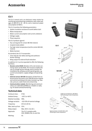
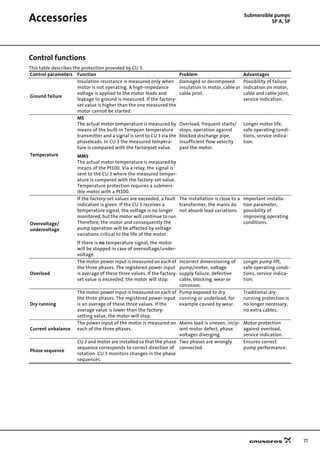
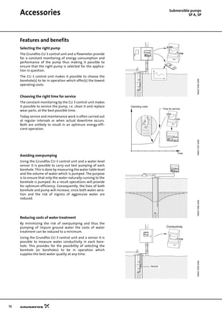
![79
Accessories Submersible pumps
SP A, SP
Motor protection via CU 3
Monitoring parameters (Diodes)
• Power on
• Motor on
• Motor temperature
• Ground failure
• Overload/dry running
• Overvoltage/undervoltage
• Current unbalance
• Direction of rotation.
Control unit CU 3 with R100
remote control and printer
Monitoring parameters (Diodes)
• Power on
• Motor on
• Motor temperature
• Ground failure
• Overload/dry running
• Overvoltage/undervoltage
• Current unbalance
• Direction of rotation.
TM0079771702
CU 3
Netz ein
Massefehler
Motortemperatur Phasenfolge
Stromasymmetrie
Reset
Motor læuft
Trockenlauf (blinkt) / !berlast (leuchtet)
Unterspannung (blinkt) / !berspannung (leuchtet)
Signal converter
1-12 [A], 10-120 [A]
or single transformers
100-400 A
3 x 400 V, 50 Hz
3 x 500 V, 50 Hz
Control cabinet
Ground level
Water level
Riser pipe
Submersible pump
Submersible motor with Tempcon or Pt100
Connection to pump
No extra cable required
High-frequency signals
CU 3
TM0079781702
CU 3
R 100
Netz ein
Massefehler
Motortemperatur Phasenfolge
Stromasymmetrie
Reset
Motor læuft
Trockenlauf (blinkt) / !berlast (leuchtet)
Unterspannung (blinkt) / !berspannung (leuchtet)
SignalSignal
Submersible motor with Tempcon or Pt100
Submersible pump
Riser pipe
Water level
Inductive flowmeter
Ground level
Control cabinet
Connection to pump
No extra cable required
High-frequency signals
Wireless infra-red
communication
Signal converter
1-12 [A], 10-120 [A]
or single transformers
100-400 A
3 x 400 V, 50 Hz
3 x 500 V, 50 Hz
CU 3
R 100](https://image.slidesharecdn.com/submersiblepump-grundfos-180406163941/85/Submersible-pump-GRUNDFOS-79-320.jpg)
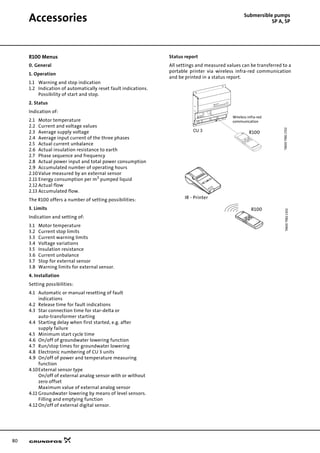
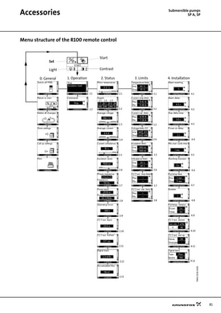
![82
Accessories Submersible pumps
SP A, SP
Complete borehole monitoring
system with CU 3 and SM 100
Monitoring parameters (Diodes)
• Power on
• Motor on
• Motor temperature
• Ground failure
• Overload/dry running
• Overvoltage/undervoltage
• Current unbalance
• Direction of rotation
SM 100
The SM 100 sensor module can be connected to eight
analog sensors and have eight digital inputs for sensors,
e.g. monitoring
- pH value
- conductivity
- O2
- pressure
- etc.
Maximum connection to the GENIbus:
• 28 CU 3 units, or
• 14 CU 3 units and 14 SM 100 units, or
• 27 CU 3 and 1 SM 100.
Product numbers
TM0079791702
PC
CU 3 SM 100
RS-485
(not supplied with the unit)
Gateway
(not supplied with
the unit)Communication
module
Digital inputs
For analog sensors
Control cabinet
Ground level
Inductive flowmeter
Water level
Riser pipe
Submersible pump
Submersible motor with Tempcon or Pt100
Signal converter
1-12 [A], 10-120 [A]
or single-turn
transformers
100-400 A
3 x 400 V, 50 Hz
3 x 500 V, 50 Hz
Connection to pump
No extra cable required
High-frequency signals
TM0079801702
CU 3 - 3 x 400 V
Product number
Current range for signal converter [A]
1-12 10-120 100-400
62 50 02 93
62 50 02 94
62 50 02 95
CU 3 expansion possibilities
Product Range
Product
number
Sensor module SM 100 3 x 400 [V] 00 62 61 91
Communication module RS 485 - 00 62 61 59
Remote control R100
HP printer for R100
-
-
00 62 53 33
00 62 04 80
Signal converter
1 - 12 [A] 00 62 04 97
10 - 120 [A] 00 62 04 98
100 - 400 [A] 00 62 61 48
Single-turn transformers
PC
CU3 CU3 CU3 SM100
GRUNDFOS-GENIbus
Protokoll-
umsetzer
(bauseits)
max. 1200 m
Gateway
(not supplied
with the unit)
GRUNDFOS-GENIbus](https://image.slidesharecdn.com/submersiblepump-grundfos-180406163941/85/Submersible-pump-GRUNDFOS-82-320.jpg)
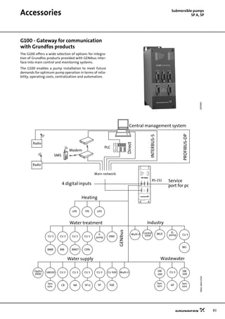
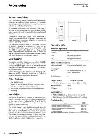
![85
Accessories Submersible pumps
SP A, SP
MTP 75 motor protection
Long motor life
The MTP 75 protects against too high motor tempera-
ture. This is the most simple and the cheapest way of
ensuring long motor life. The customer is certain that
operating conditions are observed and is given indica-
tion of the time when a service check should be made.
Too high motor temperature may be caused by:
• Overload
• Frequent starting/stopping (hunting)
• Operation against closed valve/frozen discharge pipe
• Insufficient flow of liquid past the motor
• Pumping of too hot water
• Deposits on the motor
• Overvoltage
• Undervoltage
• Current unbalance
• Dry running (Note that the pump is not protected if
the water table is below the pump inlet. For example
this may occur if several boreholes are located close
to each other).
Application and installation
The MTP 75 can be used only for motors with built-in
temperature transmitter and should be installed for
instance in a control cabinet. The MTP 75 may be
installed in any type of control cabinet containing a
thermal relay with differential release and contactor.
The thermal relay is necessary to protect against
blocking or phase failure, since this will cause the
temperature to rise much faster than the MTP 75 is able
to register.
The MTP 75 is supplied with base for mounting on DIN
rail.
Operation
The temperature transmitter will send a high-frequency
signal indicating the motor temperature through the
motor supply cable. The MTP 75 will stop the motor via
the contactor if the temperature rises above 75°C. The
temperature limit is factory-set and cannot be changed.
Display:
No light: Motor stopped. No supply voltage or electrical
fault at temperature measuring.
Green light: Motor in operation and motor temperature
OK, i.e. below 75°C.
Red light: Motor stopped and motor temperature too
high, i.e. above 75°C.
The MTP 75 is reset manually by pressing the reset
button on the front cover or by switching off the voltage
supply to the MTP 75.
No unnecessary downtime
Since the MTP 75 measures only the temperature and no
other parameters causing a temperature rise, the motor
and thus the pump will stop only when the motor
temperature is too high.
Reliability
The MTP 75 is reliable due to its simple construction and
because it requires no extra cables in the borehole.
Technical data of MTP 75
Supply voltage: 2 variants:
1 x 200-240 V ±10%, 50/60 Hz
3 x 380-415 V ±10%, 50/60 Hz
A transformer is required for
voltages over 415 V.
Control voltage: Contact load:
Maximum 415 V/3 A
Minimum 12 V/20 mA.
Enclosure class: IP 20
Operating conditions: Min. temperature: –20°C
Max. temperature: +60°C
Relative humidity: 99%.
Storage: Min. temperature: –20°C
Max. temperature: +60°C
Relative humidity: 99%.
Approvals: Complying with the regulations
of VDE and DEMKO.
Product numbers
MTP 75 without plug-in base, capacitor and signal trans-
former:
MTP 75 complete with plug-in base, capacitor and signal
transformer:
GR1915
TM0078741102
Voltage range [V] Product number
1 x 200-240 00 62 51 78
3 x 380-415 00 62 51 79
Voltage range [V] Product number
1 x 200-240 00 62 58 04
3 x 380-415 00 62 58 05
35 mm
78 mm
104 mm](https://image.slidesharecdn.com/submersiblepump-grundfos-180406163941/85/Submersible-pump-GRUNDFOS-85-320.jpg)
![86
Accessories Submersible pumps
SP A, SP
Connecting pieces
The tables below show the range of connecting pieces
for connection of thread to flange and thread to thread.
Thread - Flange Thread - Thread
TM0123961698
L
A
B
F
D
C
v1
v2
E
x
n
TM0123971698
L
B
A
Type Pump outlet Connecting piece
Thread - Flange
Product number
A
Dimensions [mm]
v1 v2 n
B C D E F L
DIN W.-Nr.
1.4301
DIN W.-Nr.
1.4401
SP 17 Rp 2.5
R 2½ → JIS 2 R 2½ 100 50.5 30 ø11 125 200 30 120 6 00 12 51 22 00 12 56 18
R 2½ → JIS 2.5 R 2½ 115 57 30 ø11 140 200 22.5 90 8 00 12 51 23 00 12 56 19
R 2½ → DN 50 PN 16 R 2½ 125 62.5 22 ø18 165 95 45 180 4 ID 81 42
R 2½ → DN 50 PN 40 R 2½ 125 62.5 22 ø18 165 97 45 180 4 ID 81 43
R 2½ → DN 65 PN 16 R 2½ 145 72.5 22 ø18 185 100 45 180 4 ID 81 44
R 2½ → DN 65 PN 40 R 2½ 145 72.5 25 ø18 185 110 22.5 180 8 ID 81 45
R 2½ → DN 80 PN 16 R 2½ 160 80 25 ø18 200 95 22.5 180 8 ID 81 46
R 2½ → DN 80 PN 40 R 2½ 160 80 25 ø18 200 99 22.5 180 8 ID 81 47
SP 30 Rp 3
R 3 → JIS 3 R 3 136 66 35 ø15 165 200 22.5 90 8 00 13 51 21 00 13 56 17
R 3 → DN 65 PN 16 R 3 145 72.5 22 ø18 185 105 45 180 4 ID 81 52
R 3 → DN 65 PN 40 R 3 145 72.5 25 ø18 185 109 22.5 180 8 ID 81 53
R 3 → DN 80 PN 16 R 3 160 80 25 ø18 200 110 22.5 180 8 ID 81 54
R 3 → DN 80 PN 40 R 3 160 80 25 ø18 200 120 22.5 180 8 ID 81 55
R 3 → DN 100 PN 16 R 3 180 90 25 ø18 220 107 22.5 180 8 ID 81 56
R 3 → DN 100 PN 40 R 3 190 95 25 ø22 220 109 22.5 180 8 ID 81 57
SP 46
SP 60
Rp 3
Rp 4
R 4 → JIS 4 R 4 155 72 35 ø15 180 200 22.5 90 8 00 15 51 24 00 15 56 22
R 3 → DN 65 PN 16 R 3 145 72.5 22 ø18 185 105 45 180 4 ID 81 52
R 3 → DN 65 PN 40 R 3 145 72.5 25 ø18 185 109 22.5 180 4 ID 81 53
R 3 → DN 80 PN 16 R 3 160 80 25 ø18 200 110 22.5 180 8 ID 81 54
R 3 → DN 80 PN 40 R 3 160 80 25 ø18 200 120 22.5 180 8 ID 81 55
R 3 → DN 100 PN 16 R 3 180 90 25 ø18 220 107 22.5 180 8 ID 81 56
R 3 → DN 100 PN 40 R 3 190 95 25 ø22 220 109 22.5 180 8 ID 81 57
R 4 → DN 100 PN 16 R 4 180 90 25 ø18 220 120 22.5 180 8 ID 81 58
R 4 → DN 100 PN 40 R 4 190 95 25 ø22 235 130 22.5 180 8 ID 81 59
SP 77
SP 95
Rp 5
R 5 → JIS 4 R 5 155 75 35 ø15 180 313 22.5 90 8 00 19 50 42 00 19 55 45
R 5 → JIS 5 R 5 190 97 45 ø19 225 315 22.5 90 8 00 19 50 43 00 19 55 46
R 5 → DN 100 PN 16 R 5 180 95 45 ø18 225 315 22.5 90 8 00 19 89 26 00 19 89 76
R 5 → DN 100 PN 40 R 5 190 102.5 45 ø22 240 314 22.5 90 8 00 19 89 27 00 19 89 77
R 5 → DN 125 PN 16 R 5 210 110 45 ø18 250 317 22.5 90 8 00 19 89 14 00 19 89 64
R 5 → DN 125 PN 40 R 5 220 120 45 ø26 270 317 22.5 90 8 00 19 89 15 00 19 89 65
R 5 → DN 150 PN 16 R 5 240 127.5 45 ø22 285 317 22.5 90 8 00 19 89 04 00 19 89 54
R 5 → DN 150 PN 40 R 5 250 135 45 ø26 300 323 22.5 90 8 00 19 89 05 00 19 89 55
SP 125
SP 160
SP 215
Rp 6
R 6 → JIS 5 R 6 190 97 45 ø19 225 316 22.5 90 8 00 20 51 28 00 20 56 28
R 6 → JIS 6 R 6 224 111 45 ø19 252 317 22.5 90 8 00 20 51 29 00 20 56 29
R 6 → DN 125 PN 16 R 6 210 110 45 ø18 250 317 22.5 90 8 00 19 89 28 00 19 89 78
R 6 → DN 125 PN 40 R 6 220 120 45 ø26 270 321 22.5 90 8 00 19 89 29 00 19 89 79
R 6 → DN 150 PN 16 R 6 240 127.5 45 ø22 285 317 22.5 90 8 00 19 89 16 00 19 89 66
R 6 → DN 150 PN 40 R 6 250 135 45 ø26 300 323 22.5 90 8 00 19 89 17 00 19 89 67
R 6 → DN 200 PN 16 R 6 295 155 45 ø22 340 317 15 90 12 00 19 89 06 00 19 89 56
R 6 → DN 200 PN 40 R 6 320 172.5 45 ø30 375 327 15 90 12 00 19 89 07 00 19 89 57
Type Pump outlet Connecting piece
Thread - Thread
Product number
A
Dimensions
Length [mm] DIN W.-Nr. 1.4301 DIN W.-Nr. 1.4401
SP 77
SP 95
Rp 5
R 5 → Rp 4 R 5 121 19 00 63 19 05 85
R 5 → Rp 6 R 5 150 19 00 69 19 05 91
NPT 5
NPT 5 → NPT 4 NPT 5 121 19 00 64 19 05 86
NPT 5 → NPT 6 NPT 5 150 19 00 70 19 05 92
SP 125
SP 160
SP 215
Rp 6 R 6 → Rp 5 R 5 150 20 01 30 20 06 40
NPT 6 NPT 6 → NPT 5 NPT 6 150 20 01 35 20 06 45](https://image.slidesharecdn.com/submersiblepump-grundfos-180406163941/85/Submersible-pump-GRUNDFOS-86-320.jpg)
![87
Accessories Submersible pumps
SP A, SP
Cable termination kit with plug
Cable termination kit type KM
Zinc anodes
Application
Cathodic protection by means of zinc can be used for
corrosion protection of SP pumps in chloride-containing
liquids such as brackish water and sea water.
Sacrificial anodes are placed on the outside of the pump
and motor as protection against corrosion.
The number of anodes required depends on the pump
and motor in question.
Please contact Grundfos for further details.
Liquid temperatures
Sea water: Up to 35°C
Brackish water
(min. 1500 g/m3
chloride): Up to 35°C.
Anode life
The zinc anodes have a life of one to four years,
depending on operating conditions (temperature, flow
and chloride content).
Product numbers of zinc anodes
TM0078832296
Description Version Prod. no.
For watertight joining of motor cable and
submersible drop cable in an acrylic tube
filled with resin. Used for both single and
multi-core cables during installation of
submersible pumps.
24 hours of hardening is required.
MS 402 and MS 4000 up to 7.5 kW:
For cables up to 4 x 2.5 mm2 79 99 01
For cables up to 4 x 6 mm2 79 99 02
TM0078852296
Description Version
Prod. no.
For watertight shrink-joining of motor
cable and submersible drop cable.
Enables the joining of:
- cables of equal size.
- cables of different sizes.
- a cable lead and a single-lead.
The joint is ready for use after a few min-
utes and requires no long hardening time as
do resin joints.
The joint cannot be separated.
Motor cable [mm2
]
Number
of leads
Flat cable
1.5 - 6.0
1.5 - 4.0
3
4
00 11 62 51
Flat cable
6 - 10
10 - 16
4
3
00 11 62 52
Flat cable 16 - 25
3
4
00 11 62 55
3 single leads 1.5 - 6.0 3 00 11 62 53
3 single leads 10 - 25 3 00 11 62 54
4 single leads 1.5 - 4.0 4 00 11 62 57
4 single leads 6 - 16 4 00 11 62 58
Zinc anodes for pumps
Product
number
Used for pump type
SP17
SP30
SP46
SP60
SP77
SP95
SP125
SP160
SP215
96 42 14 45
96 42 14 47
96 42 14 48
96 42 14 49
96 42 14 50
Zinc anodes for motors
4" Motors 6" Motors 8" Motors 12" Motors
96 42 14 44 96 42 14 46 96 42 14 50 96 42 14 51](https://image.slidesharecdn.com/submersiblepump-grundfos-180406163941/85/Submersible-pump-GRUNDFOS-87-320.jpg)
![88
Accessories Submersible pumps
SP A, SP
Flow sleeves
Grundfos offers a complete range of stainless steel flow
sleeves for both vertical and horizontal operation. Flow
sleeves are recommended for all applications in which
motor cooling is insufficient. The result is a general
extension of motor life. Flow sleeves are to be fitted:
• if the submersible pump is exposed to high thermal
load like current unbalance, dry running, overload,
high ambient temperature, bad cooling conditions.
• if aggressive liquids are pumped, since corrosion is
doubled for every 10°C the temperature rises.
• If sedimentation or deposits occur around and/or on
the motor.
Note: More information about accessories is available
on request.
SA-SPM control boxes
Application
SA-SPM control boxes are used as starting units for
single-phase, 3-wire motors, types MS 402B and MS
4000.
SA-SPM 2 is used for single-phase MS 402B motors with
a power input lower than or equal to 0.75 kW.
SA-SPM 3 is used for single-phase MS 402B and MS 4000
motors with a power input higher than or equal to 1.1
kW. SA-SPM 3 incorporates a motor starter and thus
protects the motor against overload.
Technical data
Enclosure class: IP 42.
Ambient temperature: –20°C to 60°C.
Relative humidity: Maximum 95%, normal non-
aggressive atmosphere.
Product numbers
Capacitors for MS 402B PSC
MS 402B PSC motors must be connected to the mains via
a run capacitor that is permanently connected during
operation.
Product numbers
SA-SPM control box
Product number
50 Hz
1x220-230V
1x240V
SA-SPM2
SA-SPM3
MS 402B MS 4000
0.37kW
0.55kW
0.75kW
1.1kW
1.5kW
2.2kW
82 21 95 12
82 21 95 13
82 21 95 14
82 21 93 15
82 21 93 06
82 21 93 07
82 24 95 12
82 24 95 13
82 24 9514
82 24 93 15
82 24 93 06
82 24 93 07
TM0107512197-TM0107502197
Capacitors for MS 402B PSC
Capacitor
size
Power
[kW]
Capacitor part
no.
Control box part
no.
16 µF, 400 V, 50 Hz 0.37 ID 29 70 96 02 37 91
20 µF, 400 V, 50 Hz 0.55 ID 29 71 96 02 37 92
30 µF, 400 V, 50 Hz 0.75 ID 29 73 96 02 37 93
40 µF, 400 V, 50 Hz 1.1 ID 29 74 96 02 37 94](https://image.slidesharecdn.com/submersiblepump-grundfos-180406163941/85/Submersible-pump-GRUNDFOS-88-320.jpg)
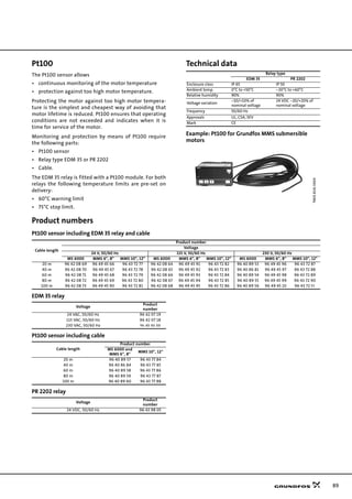
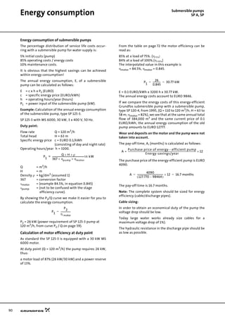
![91
Submersible pumps
SP A, SPCable sizing
Cables
Grundfos offers submersible drop cables for all applica-
tions: 3-core cable, 4-core cable, single leads.
Cables for Grundfos 4" submersible motors are available
with or without plugs. The submersible drop cable is
chosen according to application and type of installation.
Standard version: Max. liquid temperature +60°C.
Hot water version: Max. liquid temperature +70°C, for
short periods up to +90°C
(For MS only).
Tables indicating cable dimension in borehole
The tables indicate the maximum length of drop cables
in metres from motor starter to pump at direct-on-line
starting at different cable dimensions.
If star/delta starting is used the current will be reduced
by (I x 0.58), meaning that the cable length may be
longer (L x 1.73) than indicated in the tables.
If for example the operating current is 10% lower than
the full-load current, the cable must be 10% longer than
indicated in the tables.
The calculation of the cable length is based on a
maximum voltage drop of 1% and 3% of the nominal
voltage and a water temperature of maximum 30°C.
In order to minimize operating losses the cable cross
section may be increased compared to what is indicated
in the tables. This is economical only if the borehole
provides the necessary space, and if the operational time
of the pump is long, especially if the operating voltage is
below the rated voltage.
The table values are calculated on the basis of the
formula:
Max. cable length of a single-phase submersible pump:
Max. cable length of a three-phase submersible pump:
where
U = Rated voltage [V]
∆U = Voltage drop [%]
I = Rated current of the motor [A]
q = Cross-section of submersible drop
cable [mm2
]
XL = Inductive resistance: 0.078 x 10⁻³
[Ω/m]
cosϕ = Power factor
sinϕ =
ρ = Specific resistance: 0.02 [Ω mm2
/m]
Example:
Motor size: 30 kW, MMS 8000
Rated current: 64.0 A
Rated voltage: 3 x 400 V, 50 Hz
Starting method: Direct-on-line
Power factor: cosϕ = 0.85
Voltage drop: 3%
Cross-section: 25 mm2
sinϕ: 0.54
L = 150 m
Cable dimensions at 1 x 230 V, 50 Hz
3
3
L
U ∆U×
I 2× 100 ϕcos
ρ
q
--- ϕsin X
L
×+×
⎝ ⎠
⎛ ⎞××
-------------------------------------------------------------------------------------------- m[ ]=
L
U ∆U×
I 1.73 100× ϕcos
ρ
q
--- ϕsin X
L
×+×
⎝ ⎠
⎛ ⎞××
--------------------------------------------------------------------------------------------------- m[ ]=
Motor kW In [A] 1.5 mm2
2.5 mm2
4 mm2
6 mm2
10 mm2
4"
0.37 4.0 111 185 295 440 723
0.55 5.8 80 133 211 315 518
0.75 7.5 58 96 153 229 377
1.1 7.3 48 79 127 190 316
1.5 10.2 34 57 92 137 228
2.2 14 43 68 102 169
Maximum cable length in metres from motor starter to pump.
1 ϕcos2–
L
400 3×
64.0 1.73× 100× 0.85
0.02
25
-----------× 0.54 0.078× 10
-3
×+
⎝ ⎠
⎛ ⎞×
-------------------------------------------------------------------------------------------------------------------------------------------=](https://image.slidesharecdn.com/submersiblepump-grundfos-180406163941/85/Submersible-pump-GRUNDFOS-91-320.jpg)
![92
Cable sizing Submersible pumps
SP A, SP
Cable dimensions at 3 x 400 V, 50 Hz
Voltage drop: 1%.
Motor kW In [A] Cos ϕ 100%
Dimensions [mm2
]
1.5 2.5 4 6 10 16 25 35 50 70 95 120 150 185 240 300
4" 0.37 1.4 0.64 192 318 506 752
4" 0.55 2.2 0.64 122 203 322 479 783
4" 0.75 2.3 0.72 104 173 275 409 672
4" 1.1 3.4 0.72 70 117 186 277 455 712
4" 1.5 4.2 0.75 55 91 145 215 354 556 844
4" 2.2 5.5 0.82 38 64 101 151 249 393 599 818
4" 3.0 7.85 0.77 29 47 75 112 185 291 442 601 822
4" 4.0 9.6 0.8 22 37 59 89 146 230 350 477 656 874
4" 5.5 13 0.81 16 27 43 65 107 168 256 349 480 641 821 983
4" 7.5 18.8 0.78 20 31 46 76 120 183 248 340 452 577 687 804 923
6" 5.5 13.6 0.77 16 27 44 65 107 168 255 347 475 629 801 953
6" 7.5 17.6 0.8 12 20 32 48 80 125 191 260 358 477 610 728 855 984
6" 9.2 21.8 0.81 16 26 39 64 100 153 208 287 382 490 586 689 795 935
6" 11 24.8 0.83 14 22 33 55 86 132 180 248 332 427 512 604 699 826 942
6" 13 30 0.81 19 28 46 73 111 151 208 278 356 426 501 577 680 772
6" 15 34 0.82 24 40 64 97 132 182 244 313 375 441 510 601 684
6" 18.5 42 0.81 20 33 52 79 108 149 198 254 304 358 412 486 551
6" 22 48 0.84 28 44 67 92 127 170 220 264 312 361 428 489
6" 26 57 0.84 24 37 57 78 107 144 185 222 263 304 361 412
6" 30 66.5 0.83 32 49 67 92 124 159 191 225 261 308 351
6" 37 85.5 0.79 40 54 74 99 126 150 176 203 238 269
8" 22 48 0.84 28 44 67 92 127 170 220 264 312 361 428 489
8 26 56.5 0.85 23 37 57 78 107 144 186 224 265 307 365 418
8" 30 64 0.85 33 50 68 95 127 164 197 234 271 322 369
8" 37 78.5 0.85 27 41 56 77 104 134 161 191 221 263 301
8" 45 96.5 0.82 34 47 64 86 110 132 155 180 212 241
8" 55 114 0.85 38 53 71 92 111 131 152 181 207
8" 63 132 0.83 47 62 80 96 113 131 155 177
8" 75 152 0.86 40 53 69 83 98 114 136 156
8" 92 186 0.86 43 56 68 80 94 111 128
8" 110 224 0.87 47 56 67 78 93 107
10" 75 156 0.84 52 68 81 96 111 132 151
10" 92 194 0.82 43 55 66 77 89 105 120
10" 110 228 0.84 46 56 66 76 90 103
10" 132 270 0.84 47 55 64 76 87
10" 147 315 0.81 48 55 65 74
10" 170 365 0.81 56 63
10" 190 425 0.79 48 54
12" 147 305 0.83 49 57 67 77
12" 170 345 0.85 50 60 68
12" 190 390 0.84 53 60
12" 220 445 0.85 53
12" 250 505 0.85
Max. current for cable [A] 18.5 25 34 43 60 80 101 126 153 196 238 276 319 364 430 497
At particularly favourable heat dissipation conditions.
Maximum cable length in metres from motor starter to pump.](https://image.slidesharecdn.com/submersiblepump-grundfos-180406163941/85/Submersible-pump-GRUNDFOS-92-320.jpg)
![93
Cable sizing Submersible pumps
SP A, SP
Cable dimensions at 3 x 400 V, 50 Hz
Voltage drop: 3%
Motor kW In [A] Cos ϕ 100%
Dimensions [mm2
]
1.5 2.5 4 6 10 16 25 35 50 70 95 120 150 185 240 300
4" 0.37 1.4 0.64 576 955
4" 0.55 2.2 0.64 366 608 966
4" 0.75 2.3 0.72 312 518 824
4" 1.1 3.4 0.72 211 350 558 830
4" 1.5 4.2 0.75 164 273 434 646
4" 2.2 5.5 0.82 115 191 304 453 748
4" 3.0 7.85 0.77 86 142 226 337 555 872
4" 4.0 9.6 0.8 67 112 178 266 438 689
4" 5.5 13 0.81 49 82 130 194 320 504 768
4" 7.5 18.8 0.78 59 93 139 229 360 548 745
6" 5.5 13.6 0.77 49 82 131 195 320 503 765
6" 7.5 17.6 0.8 37 61 97 145 239 376 573 781
6" 9.2 21.8 0.81 49 78 116 191 300 458 625 860
6" 11 24.8 0.83 42 67 99 164 258 395 540 744 995
6" 13 30 0.81 56 84 139 218 333 454 625 833
6" 15 34 0.82 73 121 191 291 397 547 731 938
6" 18.5 42 0.81 60 99 156 238 324 446 595 763 913
6" 22 48 0.84 84 132 202 276 382 511 659 792 935
6" 26 57 0.84 71 111 170 233 321 431 555 667 788 913
6" 30 66.5 0.83 96 147 201 277 371 477 573 676 782 925
6" 37 85.5 0.79 119 162 223 296 378 451 529 608 713 806
8" 22 48 0.84 84 132 202 276 382 511 659 792 935
8" 26 56.5 0.85 70 111 170 233 322 432 557 671 794 922
8" 30 64 0.85 98 150 205 284 381 492 592 701 814 967
8" 37 78.5 0.85 80 122 168 232 311 401 483 572 664 789 903
8" 45 96.5 0.82 102 140 193 257 330 396 466 539 635 723
8" 55 114 0.85 115 159 214 276 333 394 457 543 622
8" 63 132 0.83 140 187 240 289 340 394 466 531
8" 75 152 0.86 119 160 206 249 295 343 409 469
8" 92 186 0.86 130 169 203 241 281 334 383
8" 110 224 0.87 140 169 200 233 279 321
10" 75 156 0.84 157 203 244 288 334 395 452
10" 92 194 0.82 128 164 197 232 268 316 360
10” 110 228 0.84 139 167 197 228 271 309
10" 132 270 0.84 141 166 193 228 261
10" 147 315 0.81 143 165 194 221
10" 170 365 0.81 168 190
10" 190 425 0.79 143 162
12" 147 305 0.83 147 170 202 230
12" 170 345 0.85 151 179 205
12" 190 390 0.84 158 181
12" 220 445 0.85 159
12" 250 505 0.85
Max. current for cable [A] 18.5 25 34 43 60 80 101 126 153 196 38 276 319 364 430 497
At particularly favourable heat dissipation conditions.
Maximum cable length in metres from motor starter to pump.](https://image.slidesharecdn.com/submersiblepump-grundfos-180406163941/85/Submersible-pump-GRUNDFOS-93-320.jpg)
![94
Cable sizing Submersible pumps
SP A, SP
Dimensioning of cable
Calculation of the cross-section of the cable
Formula designations
U = Rated voltage [V]
∆U = Voltage drop [%]
I = Rated current of the motor [A]
q = Cross-section [mm2
]
XL = Inductive resistance 0.078 x 10⁻³
[Ω/m]
cosϕ = Power factor
sinϕ =
L = Length of cable [m]
∆p = Power loss [W]
ρ = 1/χ
Materials of cable:
Cubber: χ = 52 m/Ω x mm2
Aluminium: χ = 35 m/Ω x mm2
For calculation of the cross-section of the submersible
drop cable, use the following formula:
DOL
Star-delta
The values of the rated current (I) and the power fac-
tor (cosϕ) can be read in the tables on the pages
page 71-75.
Calculation of the power loss
For calculation of the power loss in the submersible drop
cable, use the following formula:
Example:
Motor size: 45 kW, MMS 8000
Rated current: In = 96.5 A
Voltage: 3 x 400 V, 50 Hz
Starting method: Direct-on-line
Required cable length: 200 m
Water temperature: 30°C
Cable selection:
Choice A: 3 x 150 mm2
Choice B: 3 x 185 mm2
Calculation of power loss
Choice A:
Choice B:
Savings
Operating hours/year: h = 4000.
Annual saving (A):
By choosing the cable size 3 x 185 mm2
instead of 3 x 150
mm2
, an annual saving of 564 kWh is achieved.
Operating time: 10 years
Saving after 10 years (A10):
The saving in amount must be calculated in the local
currency.
1 ϕcos2–
q
l 1.73 100× L× ρ× cosϕ××
U ∆U l 1.73× 100× L× X
L
ϕsin××( )–×
--------------------------------------------------------------------------------------------------------=
q
l 100× L× ρ× cosϕ×
U ∆U l 1.73× 100× L× X
L
× ϕsin×( )–×
--------------------------------------------------------------------------------------------------------=
∆p
3 L ρ× l
2
××
q
-------------------------------=
∆pA
3 L× ρ× l
2
×
q
-------------------------------=
∆p
A
3 200× 0.02× 96.5
2
×
150
--------------------------------------------------------=
∆pA 745W=
∆pB
3 200× 0.02× 96.5
2
×
185
--------------------------------------------------------=
∆pB 604 W=
A ∆ρ
A
∆ρ
B
–( ) h× 745 W 604 W–( ) 4000× 564000 Wh 564 kWh====
A
10
A 10× 564 10× 5640 kWh== =](https://image.slidesharecdn.com/submersiblepump-grundfos-180406163941/85/Submersible-pump-GRUNDFOS-94-320.jpg)
![95
MiscellaneousTable of head losses
Head losses in ordinary water pipes
Upper figures indicate the velocity of water in m/sec.
Lower figures indicate head loss in metres per 100 metres of straight pipes.
The table is calculated in accordance with H. Lang's new
formula a = 0.02 and for a water temperature of 10°C.
The head loss in bends, slide valves, T-pieces and non-return valves is equiv-
alent to the metres of straight pipes stated in the last two lines of the table.
To find the head loss in foot valves multiply the loss in T-pieces by two.
Quantity of water Head losses in ordinary water pipes
m3/h Litres/min. Litres/sec.
Nominal pipe diameter in inches and internal diameter in [mm]
½"
15.75
¾"
21.25
1"
27.00
1¼"
35.75
1½"
41.25
2"
52.50
2½"
68.00
3"
80.25
3½"
92.50
4"
105.0
5"
130.0
6"
155.5
0.6 10 0.16
0.855
9.910
0.470
2.407
0.292
0.784
0.9 15 0.25
1.282
20.11
0.705
4.862
0.438
1.570
0.249
0.416
1.2 20 0.33
1.710
33.53
0.940
8.035
0.584
2.588
0.331
0.677
0.249
0.346
1.5 25 0.42
2.138
49.93
1.174
11.91
0.730
3.834
0.415
1.004
0.312
0.510
1.8 30 0.50
2.565
69.34
1.409
16.50
0.876
5.277
0.498
1.379
0.374
0.700
0.231
0.223
2.1 35 0.58
2.993
91.54
1.644
21.75
1.022
6.949
0.581
1.811
0.436
0.914
0.269
0.291
2.4 40 0.67
1.879
27.66
1.168
8.820
0.664
2.290
0.499
1.160
0.308
0.368
3.0 50 0.83
2.349
41.40
1.460
13.14
0.830
3.403
0.623
1.719
0.385
0.544
0.229
0.159
3.6 60 1.00
2.819
57.74
1.751
18.28
0.996
4.718
0.748
2.375
0.462
0.751
0.275
0.218
4.2 70 1.12
3.288
76.49
2.043
24.18
1.162
6.231
0.873
3.132
0.539
0.988
0.321
0.287
0.231
0.131
4.8 80 1.33
2.335
30.87
1.328
7.940
0.997
3.988
0.616
1.254
0.367
0.363
0.263
6.164
5.4 90 1.50
2.627
38.30
1.494
9.828
1.122
4.927
0.693
1.551
0.413
0.449
0.269
0.203
6.0 100 1.67
2.919
46.49
1.660
11.90
1.247
5.972
0.770
1.875
0.459
0.542
0.329
0.244
0.248
0.124
7.5 125 2.08
3.649
70.41
2.075
17.93
1.558
8.967
0.962
2.802
0.574
0.809
0.412
0.365
0.310
0.185
0.241
0.101
9.0 150 2.50
2.490
25.11
1.870
12.53
1.154
3.903
0.668
1.124
0.494
0.506
0.372
0.256
0.289
0.140
10.5 175 2.92
2.904
33.32
2.182
16.66
1.347
5.179
0.803
1.488
0.576
0.670
0.434
0.338
0.337
0.184
12 200 3.33
3.319
42.75
2.493
21.36
1.539
6.624
0.918
1.901
0.659
0.855
0.496
0.431
0.385
0.234
0.251
0.084
15 250 4.17
4.149
64.86
3.117
32.32
1.924
10.03
1.147
2.860
0.823
1.282
0.620
0.646
0.481
0.350
0.314
0.126
18 300 5.00
3.740
45.52
2.309
14.04
1.377
4.009
0.988
1.792
0.744
0.903
0.577
0.488
0.377
0.175
0.263
0.074
24 400 6.67
4.987
78.17
3.078
24.04
1.836
6.828
1.317
3.053
0.992
1.530
0.770
0.829
0.502
0.294
0.351
0.124
30 500 8.33
3.848
36.71
2.295
10.40
1.647
4.622
1.240
2.315
0.962
1.254
0.628
0.445
0.439
0.187
36 600 10.0
4.618
51.84
2.753
14.62
1.976
6.505
1.488
3.261
1.155
1.757
0.753
0.623
0.526
0.260
42 700 11.7
3.212
19.52
2.306
8.693
1.736
4.356
1.347
2.345
0.879
0.831
0.614
0.347
48 800 13.3
3.671
25.20
2.635
11.18
1.984
5.582
1.540
3.009
1.005
1.066
0.702
0.445
54 900 15.0
4.130
31.51
2.964
13.97
2.232
6.983
1.732
3.762
1.130
1.328
0.790
0.555
60 1000 16.7
4.589
38.43
3.294
17.06
2.480
8.521
1.925
4.595
1.256
1.616
0.877
0.674
75 1250 20.8
4.117
26.10
3.100
13.00
2.406
7.010
1.570
2.458
1.097
1.027
90 1500 25.0
4.941
36.97
3.720
18.42
2.887
9.892
1.883
3.468
1.316
1.444
105 1750 29.2
4.340
24.76
3.368
13.30
2.197
4.665
1.535
1.934
120 2000 33.3
4.960
31.94
3.850
17.16
2.511
5.995
1.754
2.496
150 2500 41.7
4.812
26.26
3.139
9.216
2.193
3.807
180 3000 50.0
3.767
13.05
2.632
5.417
240 4000 66.7
5.023
22.72
3.509
8.926
300 5000 83.3
4.386
14.42
90° bends. slide valves 1.0 1.0 1.1 1.2 1.3 1.4 1.5 1.6 1.6 1.7 2.0 2.5
T-pieces, non-return valves 4.0 4.0 4.0 5.0 5.0 5.0 6.0 6.0 6.0 7.0 8.0 9.0](https://image.slidesharecdn.com/submersiblepump-grundfos-180406163941/85/Submersible-pump-GRUNDFOS-95-320.jpg)
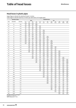
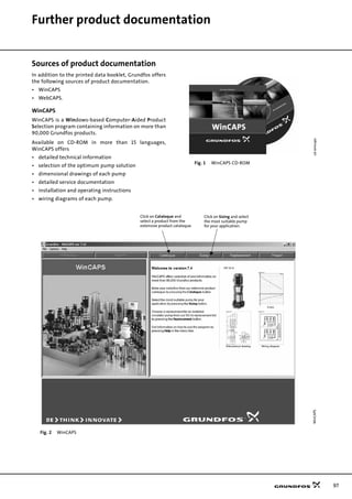
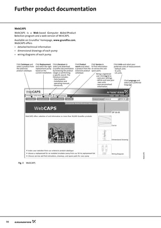
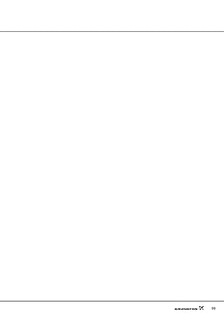
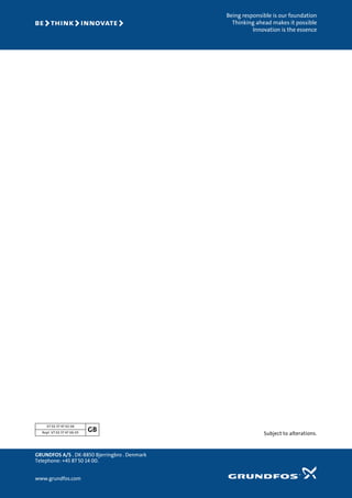

This document provides information on Grundfos submersible pumps and motors for various applications. It includes a performance range chart, applications overview, material specifications, features and benefits, and technical data. The document contains pump and motor selection information, performance curves, installation and operating guidelines to help users choose the appropriate submersible pump for their needs.


