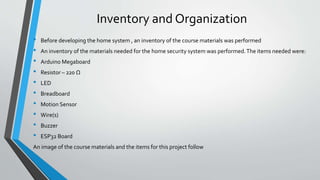
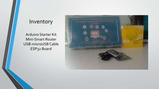
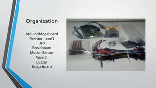
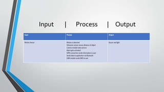
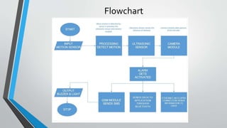
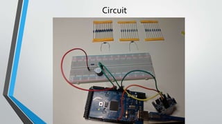
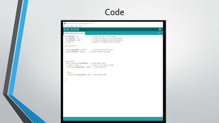
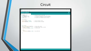
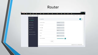
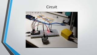
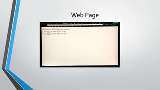
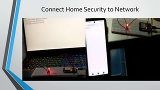
CEIS101
IoT Home Security System
By Billy Blanco
Introduction
• The Internet ofThings is growing exponentially
• This project combines all aspects of the Internet ofThings to develop a
home security system
Inventory and Organization
• Before developing the home system , an inventory of the course materials was performed
• An inventory of the materials needed for the home security system was performed.The items needed were:
• Arduino Megaboard
• Resistor – 220 Ω
• LED
• Breadboard
• Motion Sensor
• Wire(s)
• Buzzer
• ESP32 Board
An image of the course materials and the items for this project follow
Inventory
Arduino Starter Kit
Mini-Smart Router
USB-microUSB Cable
ESP32 Board
Organization
Arduino Megaboard
Resistor - 220Ω
LED
Breadboard
Motion Sensor
Wire(s)
Buzzer
Esp32 Board
Planning and Desing
• After performing an inventory of all parts of the project, a plan was created for the home
security system.
• To plan the design of the project, an IPO chart and a flowchart were generated.
• The IPO chart shows the inputs, processes, and output of the home security system.
• Planning and design of the project are crucial steps to understanding the development
process.
What are Flowcharts?
• Research was performed on types of flowcharts used and companies that
use flowcharts.
• Flowcharts are graphical representatives of processes on workflow, and the
flowchart developed illustrates the process of the home security system.
• Many companies use flowcharts as simple nerratives.
Input | Process | Output
Flowchart
Setting up the Arduino
• After planning and design, the Arduino IDE software was installed.
• This software uses Arduino sketches. Each sketch has a setup() and a loop () function in
these function code is written to run the hardware associated with the Arduino Mega.
• After the software was installed a circuit was set up.The circuit installed an LED connected
to pin 13 on the Arduino board.
• When the Arduino was connected to the computer, the port was recognized which allowed
communication between the Arduino and the computer.
• The configuration show the Arduino IDE installed and a screenshot of the circuit.
Arduino IDE
Circuit
Adding a Motion Detector and Buzzer
• I learn how to wire a motion sensor to the Mega 2560 board
• I learn how to write code that uses a motion sensor
• I learn how to integrate the motion sensor and an LED
• I learn how to integrate the motion sensor and a buzzer
• I practice writing programs using the Arduino IDE
Circuit
Code
Code Explanation
In the code, pin 7 is setup as the output based on the pinMode() function.
Pin 8 is setup as the input which is connected to the motion sensor.
The Arduino setup() function will run one time setting the input and output
pins.
Data Display
• Using the Serial Monitor on the Arduino IDE allows for data to be displayed
while the code is running.
• Simple ”motion detected” messages can be displayed on the serial monitor
along with a count of how many times motion was detected.
• Calculations can be displayed such as voltage differences. Both of these
displays are shown in the following screenshots of the code.
Circuit
Serial Monitor
Using the Serial Monitor
The code to print data to the serial monitor uses the printing() or print()
functions. For example, to print the count of the number of times motion was
detected, the Serial.printin(count)) function was used.
By viewing data on the serial monitor, information can be obtained about the
circuit that otherwise would not be known. Also it is a good debugging tool to
determine if the code is correct.
Networking and Security
• Networking can be done using the DSP32 board and breadboard rather than
the Arduino Mega board.
• To do this, the mini router was setup with a secure password and a known SSID.
• Than the ESP32 board was setupso that it can connect to the network.
• AWiFi scanwas performed using the ESP32 board for available networks.
• A web server was created and accessed via a browser or phone that allows a
user to control a light using the browser.
Router
Circuit
Web Page
Connect Home Security to Network
Challenges
• I first tested the motion sensor in a very bright room.The lights interfered
with the sensor.
• Initially the ESP32 board did not work as expected. I needed to run the get
command again so that all the files downloaded as I needed them to.
Career Skills
• Several career skills are gained in this project:
• Communication – Using flowcharts to depict the plan of the project
• Electronics (voltage, resistance, current) and working with the Arduino
• Programming using the Arduino IDE
• Networking – Setting up the router
• Security – Setting the password on the router to a secure password
Conclusion
• This project covered fundamental topics of the Internet ofThings by the
creation of a home security system.
• Building the circuit and working with the Arduino provided a hands on
learning opportunity to put into practice the topics covered in this course.

CEIS101: IoT Home Security System

  • 1.
    CEIS101 IoT Home SecuritySystem By Billy Blanco
  • 2.
    Introduction • The InternetofThings is growing exponentially • This project combines all aspects of the Internet ofThings to develop a home security system
  • 3.
    Inventory and Organization •Before developing the home system , an inventory of the course materials was performed • An inventory of the materials needed for the home security system was performed.The items needed were: • Arduino Megaboard • Resistor – 220 Ω • LED • Breadboard • Motion Sensor • Wire(s) • Buzzer • ESP32 Board An image of the course materials and the items for this project follow
  • 4.
    Inventory Arduino Starter Kit Mini-SmartRouter USB-microUSB Cable ESP32 Board
  • 5.
    Organization Arduino Megaboard Resistor -220Ω LED Breadboard Motion Sensor Wire(s) Buzzer Esp32 Board
  • 6.
    Planning and Desing •After performing an inventory of all parts of the project, a plan was created for the home security system. • To plan the design of the project, an IPO chart and a flowchart were generated. • The IPO chart shows the inputs, processes, and output of the home security system. • Planning and design of the project are crucial steps to understanding the development process.
  • 7.
    What are Flowcharts? •Research was performed on types of flowcharts used and companies that use flowcharts. • Flowcharts are graphical representatives of processes on workflow, and the flowchart developed illustrates the process of the home security system. • Many companies use flowcharts as simple nerratives.
  • 8.
  • 9.
  • 10.
    Setting up theArduino • After planning and design, the Arduino IDE software was installed. • This software uses Arduino sketches. Each sketch has a setup() and a loop () function in these function code is written to run the hardware associated with the Arduino Mega. • After the software was installed a circuit was set up.The circuit installed an LED connected to pin 13 on the Arduino board. • When the Arduino was connected to the computer, the port was recognized which allowed communication between the Arduino and the computer. • The configuration show the Arduino IDE installed and a screenshot of the circuit.
  • 11.
  • 12.
  • 13.
    Adding a MotionDetector and Buzzer • I learn how to wire a motion sensor to the Mega 2560 board • I learn how to write code that uses a motion sensor • I learn how to integrate the motion sensor and an LED • I learn how to integrate the motion sensor and a buzzer • I practice writing programs using the Arduino IDE
  • 14.
  • 15.
  • 16.
    Code Explanation In thecode, pin 7 is setup as the output based on the pinMode() function. Pin 8 is setup as the input which is connected to the motion sensor. The Arduino setup() function will run one time setting the input and output pins.
  • 17.
    Data Display • Usingthe Serial Monitor on the Arduino IDE allows for data to be displayed while the code is running. • Simple ”motion detected” messages can be displayed on the serial monitor along with a count of how many times motion was detected. • Calculations can be displayed such as voltage differences. Both of these displays are shown in the following screenshots of the code.
  • 18.
  • 19.
  • 20.
    Using the SerialMonitor The code to print data to the serial monitor uses the printing() or print() functions. For example, to print the count of the number of times motion was detected, the Serial.printin(count)) function was used. By viewing data on the serial monitor, information can be obtained about the circuit that otherwise would not be known. Also it is a good debugging tool to determine if the code is correct.
  • 21.
    Networking and Security •Networking can be done using the DSP32 board and breadboard rather than the Arduino Mega board. • To do this, the mini router was setup with a secure password and a known SSID. • Than the ESP32 board was setupso that it can connect to the network. • AWiFi scanwas performed using the ESP32 board for available networks. • A web server was created and accessed via a browser or phone that allows a user to control a light using the browser.
  • 22.
  • 23.
  • 24.
  • 25.
  • 26.
    Challenges • I firsttested the motion sensor in a very bright room.The lights interfered with the sensor. • Initially the ESP32 board did not work as expected. I needed to run the get command again so that all the files downloaded as I needed them to.
  • 27.
    Career Skills • Severalcareer skills are gained in this project: • Communication – Using flowcharts to depict the plan of the project • Electronics (voltage, resistance, current) and working with the Arduino • Programming using the Arduino IDE • Networking – Setting up the router • Security – Setting the password on the router to a secure password
  • 28.
    Conclusion • This projectcovered fundamental topics of the Internet ofThings by the creation of a home security system. • Building the circuit and working with the Arduino provided a hands on learning opportunity to put into practice the topics covered in this course.