Download to read offline


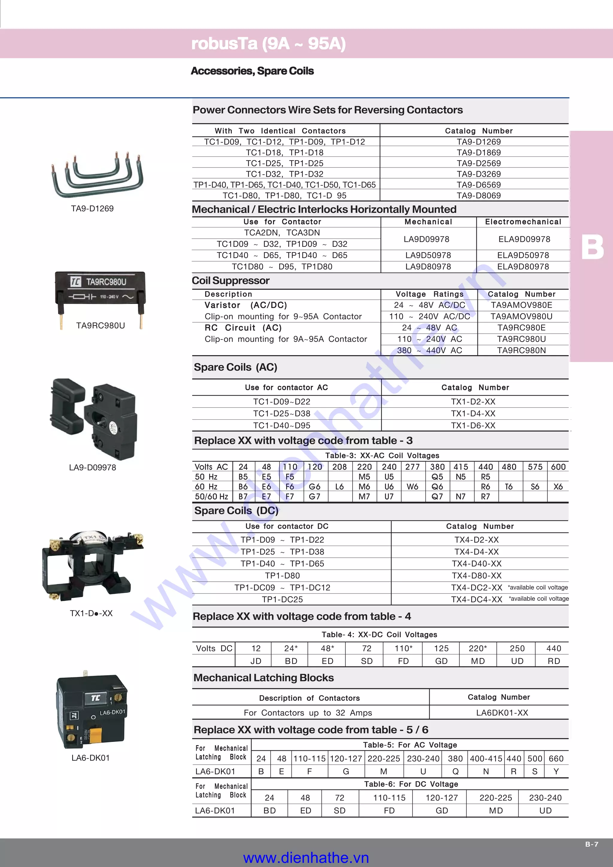


The document provides detailed specifications for 3 and 4 pole contactors with AC and DC operating coils, including insulation voltage, operational limits, and thermal currents. It lists various technical characteristics such as control voltage, average operating times, mechanical life, and breaking capacities, conforming to several international standards. Additional sections cover selection guidelines for contactors based on required electrical life and application categories.