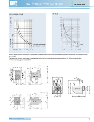
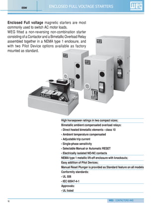
The document provides information about WEG contactors and starters. It includes:
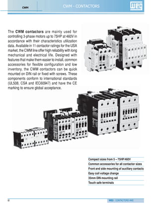
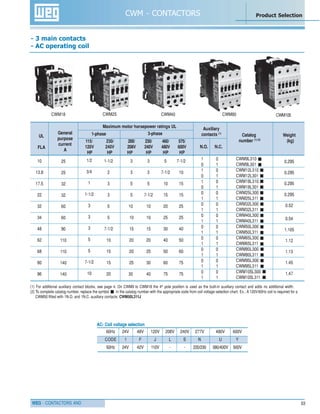
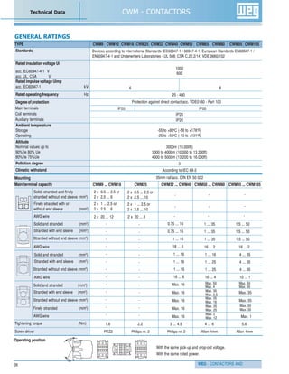
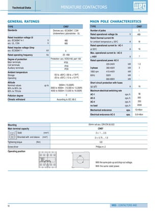
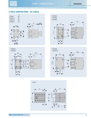
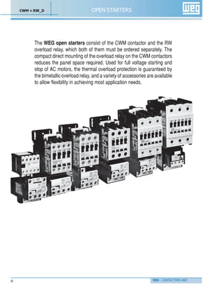
- An overview of the CWM line of contactors for controlling 3-phase motors up to 75HP at 460V, available in 11 sizes from 5-75HP.
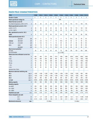
- Tables listing technical specifications for each CWM contactor size, including rated current, horsepower ratings, auxiliary contact configurations, and coil voltage options.
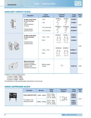
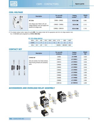
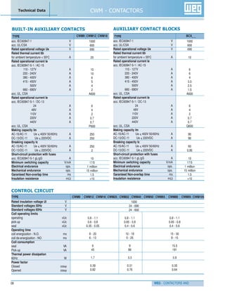
- Descriptions and part numbers for common accessories like auxiliary contact blocks, overload relays, and spare parts.

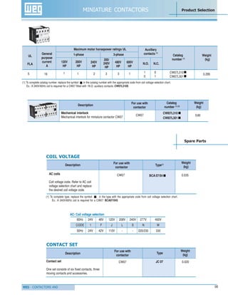
![WEG - CONTACTORS AND 19
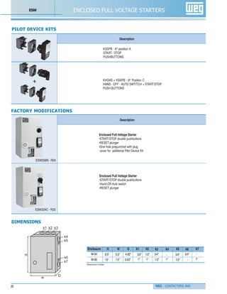
ENCLOSED FULL VOLTAGE STARTERS Product Selection
START/STOP pushbuttons KSSPB A
START/STOP pushbuttons + KSSPB +
HAND-OFF-AUTO switch KHOAS
No Pilot Device - E
ULMax Enclosure Catalog
Amps Size Number(1)
460V
115V 230V 200V 230V 460V 575V
10 1/2 1-1/2 3 3 5 7-1/2 M-04 ESW9xx-
13.8 3/4 2 3 3 7-1/2 10 M-04 ESW12xx-
17.5 1 3 5 5 10 15 M-04 ESW18xx-
22 1-1/2 3 5 7-1/2 15 15 M-04 ESW25xx-
32 2 5 10 10 20 25 M-04 ESW32xx-
34 3 5 10 10 25 25 M-06 ESW40xx-
48 3 7-1/2 15 15 30 40 M-06 ESW50xx-
62 5 10 20 20 40 50 M-06 ESW65xx-
68 5 15 20 25 50 60 M-06 ESW80xx-
E
Table 1 - Enclosed Full Voltage Non-Reversing Non-Combination Starters
Coil voltages - 60Hz
Vac 5th
position
120 A
240 B
480 C
Suffix Overload Suffix Overload
range [A] range [A]
R11 0.28-0.4 R22 10-15
R12 0.43-0.63 R23 11-17
R13 0.56-0.8 R24 15-23
R14 0.8-1.2 R25 22-32
R15 1.2-1.8 R26 25-40
R16 1.8-2.8 R27 32-50
R17 2.8-4 R28 40-57
R18 4-6.3 R29 50-63
R19 5.6-8 R30 57-70
R20 7-10 R31 63-80
R21 8-12.5
Enclosed
NEMA 1
Non-Reversing
Non-Combination
Starter
Coil Voltage
Code
CWM
ContactorWEG
Pilot Device
Code
Overload
Relay Suffix
KIT
Factory installed Pilot Device
Table 4 - Pilot Device for Non-Reversing Non-Combination Starter
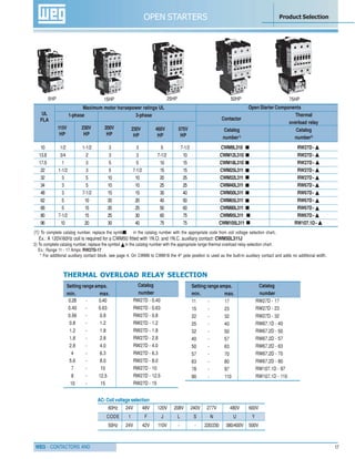
Table 2 - Coil Voltages Table 3 - Bimetallic Overload Relay selection
Other coil voltages/frequencies are available
on request.
Maximum Horsepower - 60Hz
Single-phase Three-phase
CODE
6th
position
S W 25 B A R24-
1 2 43 5 6 7
Note: Bimetallic Overload Relay mounting
R11-R25 mounting on ESW9 - ESW32
R26-R31 mounting on ESW40 - ESW80
Important: In the case that you do not know the
full-load motor-running current of the motor,
we are able to ship your ESW with the most typical
overload relay for the horsepower requested.
(1) To Complete the Starter Selection:
Select the appropriate coil voltage from table 2, and insert the coil code in the 5th position of Catalog Number.
Select the appropriate Pilot Device combination from table 4 and insert the Pilot Device code in the 6th position of Catalog Number
Select the Overload Relay from table 3 and add the suffix as the final three digits of the Catalog Number.
Ex.: A ESW 3-phase 5HP-230V with START/STOP Pushbutton and 240V ac coil voltage is required: ESW18BA-R23
Note: A ESW9-ESW32 are supplied with 1N.O. front mounted auxiliary contact and ESW40-ESW80 are supplied with 2N.O. side mounted auxiliary contact.
C](https://image.slidesharecdn.com/1-422-170825104909/85/WEG-Contactors-Oveload-Relays-21-320.jpg)