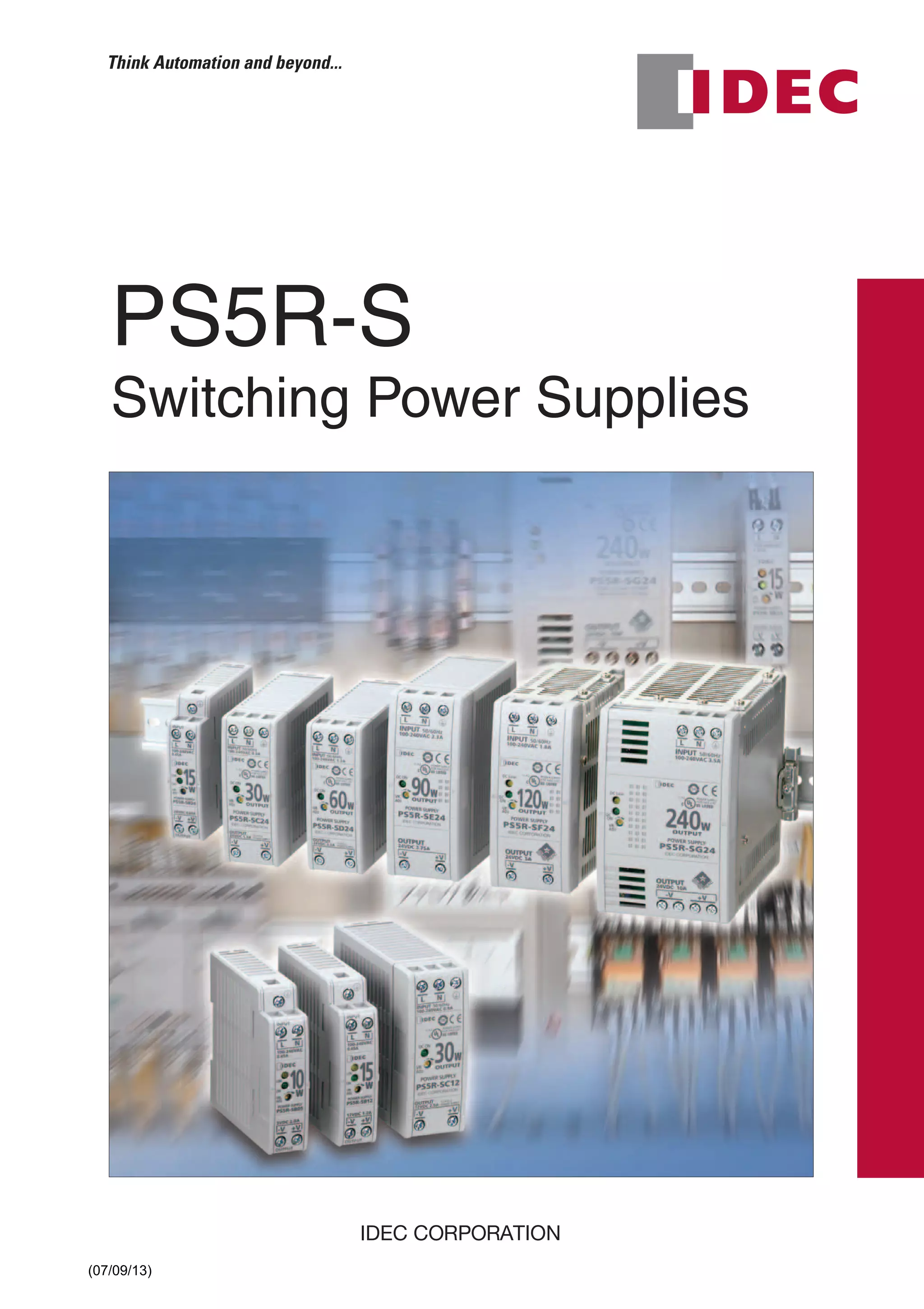
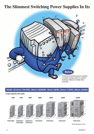
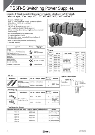
PS5R-S
Switching Power Supplies
(07/09/13)
Tư vấn chọn sản phẩm
Giao hàng tận nơi
Hỗ trợ kỹ thuật
Chính sách hậu mãi đa dạng
DỊCH VỤ CHĂM SÓC KHÁCH HÀNG TOÀN DIỆN
Nhà cung cấp thiết bị điện chuyên nghiệp
Email: contact@beeteco.com
Hotline: 0909 41 61 43
CÔNG TY TNHH THƯƠNG MẠI KỸ THUẬT ASTER
Số 7/31 KDC Thương Mại Sóng Thần, Kp. Nhị Đồng 1, P. Dĩ An, Tx. Dĩ An, Bình Dương
Tel: (0650) 3617 012
Fax: (0650) 3617 011
2
Before
The Slimmest Switching Power Supplies In Its
22.5
95
90
22.5 36
90
95
95
108
36
95
108
46
115
121
50
115
129
80
125
149.5
A cluster of switching power supplies
occupied a large space in a panel,
making it difficult to install other
products.
Width: 22.5mm (10/15W), 36mm (30/60W), 46mm (90W), 50mm (120W), 80mm (240W)
10W 15W 30W 60W 90W 120W 240W
PS5R-SB05 PS5R-SB12
PS5R-SB24
PS5R-SC12
PS5R-SC24
PS5R-SD24 PS5R-SE24 PS5R-SF24 PS5R-SG24
Large capacity slim style.
All dimensions in mm.
(07/09/13)
3
20mm minimum
After
Class Creates More Space in Your Panel.
The slim switching power supplies
provide you with more space and also
enable efficient product layout.
IDEC’s Spring-up, Fingersafe Terminal SEMI-F47 Compliant (PS5R-SF/SG)
Safety and High Quality
Panel Mounting Possible
Separate Input and Output Terminals
Spring-up, fingersafe terminals
reduce wiring time and provide
enhanced safety.
Less wiring time
• Spring-up screws are captive,
therefore screws will not be lost.
• Ring terminals can be connected.
Finger-safe
• Terminals cannot be touched,
preventing electric shocks.
Upper terminals: Input
Lower terminals: Output
Universal AC Voltage (100 to 240V AC)
3-Year Warranty
The PS5R-S switching power supplies are certified
by EPRI PEAC, and “PQ Star” is marked on the
product. SEMI-F47 “Specification for Semiconduc-
tor Processing Equipment Voltage Sag Immunity”
defines voltage sag ride-through capability design
requirements for semiconductor processing,
metrology, and automated test equipment.
Refer to operating instructions
when mounting two or more
switching power supplies in close
proximity.
Compliant with UL1604, the PS5R-S
switching power supplies can be used
in hazardous locations—Class 1 Divi-
sion 2, Groups A, B, C, and D.
UL508, UL1310 Class 2 (PS5R-SB/SC/SD), UL1604, CSA
No. 14, No. 213, No. 223, EN 60950-1, EN50178, EN61204-3
(Class B) compliant.
The PS5R-S switching power supplies can
be installed on a panel using a mounting
bracket.
Installation Example
(07/09/13)
4
PS5R-S Switching Power Supplies
Slim size DIN rail mount switching power supplies with finger-safe terminals
Universal input; Wide range 10W, 15W, 30W, 60W, 90W, 120W, and 240W
• Compact and light-weight
Width: 22.5 mm (10W/15W), 36 mm (30W/60W), 46 mm
(90W), 50 mm (120W), 80 mm (240W)
• Universal input:
10W to 90W: 85-264V AC/100-370V DC
120W and 240W: 85-264V AC/100-350V DC
• DIN rail mounting. Optional mounting bracket is available for
panel mounting.
• IP20 fingersafe spring-up screw terminals
• CE marked (LVD and EMCD)
• EN61204-3 (DC power supply EMC Directive Class B)
VCCI Class B compliant
• Meets SEMI F47 Sag Immunity (PS5R-SF/SG)
• Three-year Warranty
Approvals Marking
Organization/
File No.
UL508
UL1604
UL1310 Class 2 (PS5R-SB/SC/SD)
CSA C22.2 No. 14/213
CSA C22.2 No. 223 (PS5R-SB/SC/SD)
UL/c-UL
File No. E234997
EN50178
EN60950-1
TÜV SÜD
EN50178 (LVD)
EN60950-1 (LVD)
EN61204-3 (EMCD)
EU LVD and EMCD
SEMI F47 (PS5R-SF/SG) Semiconductor
• DIN Rail
• Mounting Clip
• Panel Mounting Bracket
Appearance Specifications Type No. Ordering Type No.
Package
Quantity
Remarks
Aluminum
Weight: Approx. 200g
BAA1000 BAA1000PN10 10
Length: 1m
Width: 35 mmSteel
Weight: Approx. 320g
BAP1000 BAP1000PN10 10
Appearance Specifications Type No. Ordering Type No.
Package
Quantity
Remarks
Zinc-plated steel
Weight: Approx. 15g
BNL5 BNL5PN10 10 Used on a DIN
rail to prevent
power sup-
plies from slid-
ing off the end.BNL6 BNL6PN10 10
Applicable Switching Power Supply Ordering Type No. Package Quantity Remarks
PS5R-SB
PS9Z-5R1B 1 For upright mounting
PS9Z-5R2B 1 For flat mounting
PS5R-SC
PS5R-SD
PS9Z-5R1C 1 For upright mounting
PS5R-SE PS9Z-5R1E 1 For upright mounting
PS5R-SF
PS5R-SG
PS9Z-5R1G 1 For upright mounting
Type No. Development
PS5R - S
Switching
Power Supply
Slim Line
Output Voltage Code
05: 5V (PS5R-SB)
12: 12V (PS5R-SB/SC)
24: 24V
Output Voltage Code
B: 10W/15W
C: 30W
D: 60W
E: 90W
F: 120W
G: 240W
Types
Output
Capacity
Type No. Input Voltage
Output
Voltage
Output
Current
10W PS5R-SB05
100 to 240V AC
(Voltage range:
85 to 264V AC
100 to 370V DC)
5V 2.0A
15W
PS5R-SB12 12V 1.2A
PS5R-SB24 24V 0.65A
30W
PS5R-SC12 12V 2.5A
PS5R-SC24 24V 1.3A
60W PS5R-SD24 24V 2.5A
90W PS5R-SE24 24V 3.75A
120W PS5R-SF24 100 to 240V AC
(Voltage range:
85 to 264V AC
100 to 350V DC)
24V 5.0A
240W PS5R-SG24 24V 10.0A
(07/09/13)
5
PS5R-S Switching Power Supplies
Specifications
Note 1: DC input voltage is not subjected to safety standards. The input voltage range approved by safety standards is 100 to 240V AC. When using on DC input,
connect a fuse to the input terminal for DC input protection.
Note 2: One minute after the output has been turned off, turn on the input again.
Reference Value
Calculation of the expected life is based on the life of the aluminum electrolytic capacitor. The expected life is subjected to operating conditions.
Type
PS5R-SB05 (10W)
PS5R-SB12 (15W)
PS5R-SB24 (15W)
PS5R-SC12
PS5R-SC24
(30W)
PS5R-SD24
(60W)
PS5R-SE24
(90W)
PS5R-SF24
(120W)
PS5R-SG24
(240W)
Input
Input Voltage
(Single-phase two-wire)
(Note 1)
100 to 240V AC
(Voltage range: 85 to 264V AC/100 to 370V DC)
(Duty ratio ≤ 80% at 100-105V DC)
100 to 240V AC
(Voltage range: 85 to 264V AC/100
to 350V DC) (Duty ratio ≤ 80% at
100-110V DC)
Frequency 50/60 Hz
Input Current
100V AC 0.45A max. 0.9A max. 1.7A max. 2.3A max. 1.8A max. 3.5A max.
200V AC 0.3A max. 0.6A max. 1.0A max. 1.4A max. 1.0A max. 1.7A max.
Inrush Current 50A max. (Ta = 25°C, 200V AC cold start)
Leakage
Current
132V AC 0.38 mA max. 0.5 mA max.
264V AC 0.75 mA max. 1.0 mA max.
Efficiency
(Typical)
5V DC 69% — — — — —
12V DC 75% 70% — — — —
24V DC 79% 80% 83% 82% 84% 84%
PowerFactor
(Typical)
100V AC — — — — 0.99 0.99
230V AC — — — — 0.90 0.92
Output
Rated Voltage/Current
5V/2.0A (PS5R-SB05)
12V/1.2A (PS5R-SB12)
24V/0.65A (PS5R-SB24)
12V/2.5A (PS5R-SC12)
24V/1.3A (PS5R-SC24)
24V/2.5A 24V/3.75A 24V/5A 24V/10A
Adjustable Voltage
Range
±10%
Output Holding Time 20 ms min.
Start Time 200 ms max. 650 ms max. 500 ms max.
Rise Time 100 ms max. 200 ms max.
Regulation
Input Fluctuation 0.4% max.
Load Fluctuation 1.5% max.
Temperature
Change
0.05%/°C max.
(–10 to +65°C)
0.05%/°C max.
(–10 to +55°C)
0.05%/°C max. (–10 to +40°C)
Ripple
(including noise)
2% p-p max.
(–10 to +65°C)
2% p-p max.
(–10 to +55°C)
2% p-p max. (–10 to +40°C) 1% p-p max. (–10 to +40°C)
Supplementary
Functions
Overcurrent Protection 105% min. (auto reset)
103 to 110%
(auto reset)
105 to 130% (auto reset)
Overvoltage Protection Output off at 120% (Note 2)
Operation Indicator LED (green)
Voltage Low Indication LED (amber) No LED (amber)
Dielectric Strength
Between input and output terminals: 3,000V AC, 1 minute
Between input and ground terminals: 2,000V AC, 1 minute
Between output and ground terminals: 500V AC, 1 minute
Insulation Resistance
Between input and output terminals: 100MΩ min. (500V DC megger)
Between input and ground terminals: 100MΩ min. (500V DC megger)
Operating Temperature
–10 to +65°C (no
freezing)
–10 to +60°C (no freezing, see the Output Derating Curves)
Storage Temperature –25 to +75°C (no freezing)
Operating Humidity 20 to 90% RH (no condensation)
Vibration Resistance 10 to 55 Hz, amplitude 0.375 m, 2 hours each in 3 axes
Shock Resistance 300 m/s2
(30G) (150 m/s2
when using panel mounting bracket, except for PS5R-SB with 300 m/s2
), 3 shocks each in 6 axes
EMC
EMI EN61204-3 (Class B)
EMS EN61204-3 (industrial)
Applicable Standards
UL508 (Listing), UL1604, UL1310 Class 2
CSA C22.2 No. 14
CSA C22.2 No. 213
CSA C22.2 No. 223
EN50178, EN60950-1
UL508 (Listing), UL1604
CSA C22.2 No. 14
CSA C22.2 No. 213,
EN50178, EN60950-1
Other Standard — SEMI F47
Dimensions (mm) 90H × 22.5W × 90D 95H × 36W × 108D
115H × 46W ×
121D
115H × 50W ×
129D
125H × 80W ×
149.5D
Weight (approx.) 160g 250g 285g 440g 630g 1000g
Terminal Screw M3.5 slotted-Phillips head screw
Expected Life 8 years minimum (at the rated input, duty ratio 50%, operating temperature +40°C, standard mounting direction)
(07/09/13)
6
PS5R-S Switching Power Supplies
Block Diagrams
• PS5R-SB/SC
• PS5R-SD/SE
• PS5R-SF/SG
V.ADJ
Fuse
L
N
Input
+V
–V
LineFilter
Rectifying
Circuit
Overcurrent
Detection
Switching
Circuit
Control
Circuit
Rectifying
Circuit
Overvoltage
Detection
Output Voltage
Detection
V.ADJ
L
N
Input
Fuse
+V
–V
LineFilter
Rectifying
Circuit
Rectifying
Circuit
Overcurrent
Detection
Switching
Circuit
Control
Circuit
Overvoltage
Detection
Output Voltage
Detection
L
N
Input
V.ADJ
+V
–V
Fuse
LineFilter
ActiveFilter
Rectifying
Circuit
Overcurrent
Detection
Switching
Circuit
Smoothing
Circuit
Control
Circuit
Control
Circuit
Rectifying
Circuit
Overvoltage
Detection
Output Voltage
Detection
(07/09/13)
7
PS5R-S Switching Power Supplies
Characteristics
• Operating Temperature vs. Output Current (Derating Curves)
Conditions: Natural air cooling
• Mounting Style
• Overcurrent Protection Characteristics
–10 0 10 20 30 40 50 60 70
0
10
20
30
40
50
60
70
80
90
100
Operating Temperature (°C)
OutputCurrent(%)
Mounting A
–10 0 10 20 30 40 50 60 6555 70
0
10
20
30
40
50
60
70
80
90
100
OutputCurrent(%)
Operating Temperature (°C)
Mounting A
Mounting B, C, D
–10 0 10 20 30 40 50 55 60 70
0
10
20
30
40
50
60
70
80
90
100
Operating Temperature (°C)
OutputCurrent(%)
Mounting A
–10 0 10 20 30 40 45 50 60 70
0
10
20
30
40
50
60
70
80
90
100
Operating Temperature (°C)
OutputCurrent(%)
Mounting A
PS5R-SC PS5R-SD/SE/SF
PS5R-SG
PS5R-SB
• Operating Temperature Approved by Safety Standards UL 508,
EN 60950-1, and EN 50178
Type No.
UL 508 EN 60950-1, EN 50178
Mounting A
Mounting
B, C, and D
Mounting A
Mounting
B, C, and D
PS5R-SB05, -SB12, -SB24 55 55 60 55
PS5R-SC12, -SC24 55 Impossible 55 Impossible
PS5R-SD24, -SE24, -SF24 40 Impossible 55 Impossible
PS5R-SG24 45 Impossible 55 Impossible
Mounting A
(Vertical)
Mounting B
(Upright)
Mounting C
(Left side up)
Up
Mounting D
(Right side up)
PSR5-SB onlyAll models
PS5R-SC
0
0
100
105%
100
Intermittent Operation
Output Current (%)
OutputVoltage(%)
0 100
0
100
105%
Intermittent Operation
Output Current (%)
OutputVoltage(%)
0 100
0
100
103% 110%
Intermittent Operation
Output Current (%)
OutputVoltage(%)
PS5R-SD
PS5R-SE PS5R-SF/SG
0 100
0
100
105% 130%
Output Current (%)
OutputVoltage(%)
PS5R-SB
100
0
100 105
Output Current (%)
OutputVoltage(%)
(07/09/13)
8
PS5R-S Switching Power Supplies
Dimensions
• PS5R-SB
• PS5R-SC/SD
• PS5R-SE
3.8
95
4.435.327.3
61.612.28.2
90
9.5
22.5
12
24.7
120
112
102
110
62.9
44
5-M3.5
Screw Terminal
2-M4 Tapped Holes or 2-ø4.5 Drilled Holes
PS9Z-5R2B
Panel Mounting Bracket
PS9Z-5R1B
Panel Mounting Bracket
108
3.8
4.524.935.3
36
95
798
20
10 10
115
105
26
38
2-M4 Tapped Holes or
2-ø4.5 Drilled Holes
5-M3.5 Terminal Screws
PS9Z-5R1C
Panel Mounting Bracket
4.544.935.3
3.8
121
115
988.5
46
23
11.5 11.5 5-M3.5 Terminal Screws
36
48
135
125
2-M4 Tapped Holes or
2-ø4.5 Drilled Holes
PS9Z-5R1E
Panel Mounting Bracket
All dimensions in mm.
(07/09/13)
9
PS5R-S Switching Power Supplies
• PS5R-SF
• PS5R-SG
135
145
48
36
3.8
4.544.935.3
12911.511.5
115
50.0
23.0
9.196.8
5-M3.5 Terminal Screws
4-M4 Tapped Holes or
4-ø4.5 Drilled Holes
PS9Z-5R1G
Panel Mounting Bracket
All dimensions in mm.
135
145
48
363.8
4.535.354.9
149.5
1010
80
10 10
10 10
9.4106.3
125
7-M3.5 Terminal Screws
4-M4 Tapped Holes or
4-ø4.5 Drilled Holes
PS9Z-5R1G
Panel Mounting Bracket
(07/09/13)
10
PS5R-S Switching Power Supplies
Parts Description
Safety Precautions
L
INPUT 50/60Hz
VR.
ADJ
DC ON
N
-V
OUTPUT
+V
-V +V
100-240VAC
INPUT
VR.
ADJ
ON
LOW
OUTPUT
• PS5R-SC/SD/SE • PS5R-SF/SG
• DC ON and DC Low Indicators
When the output voltage drops below approx. 80% of the rated value, the DC Low
LED goes on.
The status can be seen by the DC ON and DC Low indicators.
∗ The LEDs go on when the input voltage drops below 57V AC at full load.
Marking Name Description
VR.ADJ
Output Voltage
Adjustment
• Allows adjustment within ±10%.
Turning clockwise increases the output voltage.
DC ON
Operation Indicator
(Green)
• Lights when the output voltage is on.
DC Low
Output Low Indicator
(Amber)
• Lights when the output voltage drops below approx.
80% of the rated value (PS5R-SB/SF/SG only).
+V
–V
DC Output Terminals
• +V: Positive output terminal
• –V: Negative output terminal
Ground Terminal • Be sure to connect this terminal to a proper ground.
L
N
Input Terminal
• Accepts a wide range of voltage and frequency. Polar-
ity does not matter when using DC input.
Status Normal
Overload or
Input Voltage Low∗∗∗∗
Output
Short-circuit
Output OFF
DC ON LED
(Green)
ON ON OFF OFF
DC Low LED
(Amber)
OFF ON ON OFF
• PS5R-SB
• Do not use switching power supplies with electric equipment
whose malfunction or inadvertent operation may damage the
human body or life directly.
• Make sure that the input voltage and output current do not ex-
ceed the ratings. If the input voltage and output current exceed
the ratings, electric shock, fire, or malfunction may occur.
• Do not touch the terminals of the switching power supply while
input voltage is applied, otherwise electric shock may occur.
• Provide the final product with protection against malfunction or
damage that may be caused by malfunction of the switching
power supply.
• Operating temperatures should not exceed the ratings. Be sure
to note the derating characteristics. If the operating temperature
exceeds the ratings, electric shock, fire, or malfunction may oc-
cur.
• Blown fuses indicate that the internal circuits are damaged.
Contact IDEC for repair. Do not just replace the fuse and reop-
erate, otherwise electric shock, fire, or malfunction may occur.
• Do not use the switching power supplies to charge recharge-
able batteries.
• Do not overload or short-circuit the switching power supply for
a long period of time, otherwise the internal elements may be
damaged.
• Do not disassemble, repair, or modify the power supplies, oth-
erwise the high voltage internal part may cause electric shock,
fire, or malfunction.
• The fuse inside the PS5R-S switching power supply is for AC in-
put. Use DC fuse for DC input.
(07/09/13)
11
PS5R-S Switching Power Supplies
• Notes for Installation
1. When mounting the PS5R-S switching power supply, be sure
to prevent heat built-up around the PS5R-S, taking the fol-
lowing precautions into consideration.
(1) Do not close the top and bottom openings of the PS5R-S.
(2) Maintain a minimum of 20 mm clearance around the PS5R-
S, except for the top and bottom openings.
(3) When derating of the output does not work, provide forced
air-cooling.
(4) For wiring, use wires with heat resistance of 60°C or higher.
(5) Recommended tightening torque of the input and output ter-
minals is 0.8 N·m (UL listed torque value). Do not tighten to
1.8 N·m or higher.
(6) Use copper core wires of the following sizes.
Recommended wire size: AWG14 to 18
(cross section: 0.9 to 2 mm2
)
2. When mounting multiple PS5R-S switching power supplies
side by side, maintain a minimum of 20 mm clearance.
Observe the derating curves in consideration of the ambient
temperature.
3. Mounting on 35-mm-wide DIN rails
Mounting
Fasten the DIN rail to a mounting plate using screws firmly.
When mounting the PS5R-S on a DIN rail, place the PS5R-S as
shown. With the clamp inserted, press the PS5R-S towards the
DIN rail.
Removal
Insert a flat screwdriver into the slot in the clamp, and pull out
the clamp until it clicks. Turn the PS5R-S bottom out.
4. Installing the Panel Mounting Bracket
• Adjustment of Output Voltage
The output voltage can be adjusted within ±10% of the rated
output voltage by using the VR.ADJ control on the front. Turning
the VR.ADJ clockwise increases the output voltage. When
using a higher output voltage, reduce the output current to
make sure that the output capacity is within the rating. Note that
overvoltage protection may work when increasing the output
voltage.
• Overcurrent Protection
The output voltage drops automatically when an overcurrent
flows due to an overload or short circuit. Normal voltage is auto-
matically restored when the load returns to normal conditions.
• Overvoltage Protection (OVP)
The output is turned off by overvoltage protection when an overvolt-
age is applied to the input. When the output voltage has dropped
due to an overvoltage, turn the input off, and after one minute, turn
the input on again.
Instructions
Air
20 mm minimum
Mounting Removal
Clamp
<Installing PS9Z-5R2B Panel Mounting Bracket>
Latch
Panel Mounting Bracket (PS9Z-5R1)
Power
Supply
Tab
Slot
LOCK
LOCK
UNLOCK
LOCK
UNLOCK
Panel Mounting Bracket (PS9Z-5R2B)
Power
Supply
Latch
Tab
LOCK
<Installing PS9Z-5R1 Panel Mounting Bracket>
Ç Insert the tab on the panel
mounting bracket into the
slot on the power supply.
É Install the bracket as
shown on the left.
Å Push in the latch to LOCK
position.
Å Pull out the latch to
UNLOCK position.
Ç Insert the tab on the panel
mounting bracket into the
slot on the power supply.
É Push in the latch to LOCK
position.
Ñ Ensure that the panel
mounting bracket is locked
by the latch.
Ñ Ensure that the panel
mounting bracket is locked
by the latch.Ñ
É
É
(07/09/13)
PS5R-S Switching Power Supplies
• When ordering, specify the Type No. and quantity.
Ordering Information
Warranty
• Insulation/Dielectric Test
When performing an insulation/dielectric test, short-circuit the input
(between L and N) and output (between +V and –V). Do not apply or
interrupt the voltage quickly, otherwise surge voltages may be gen-
erated and the PS5R-S may be damaged.
• Series Operation
The following series operation is allowed. (When UL1310 Class 2 is
applied, series operation is not allowed.)
Connect Schottky diodes D as shown above. Select Schottky diodes
in consideration of the rated current.
• Parallel Operation
Parallel operation is not possible to increase the output capacity,
because the internal elements and load may be damaged. Redun-
dant operation is possible using the following connection.
• Redundant Operation
Redundant operation is a connection method of two switching power
supplies in parallel for emergency. Normally one switching power
supply has a sufficient output. If one switching power supply fails,
another one operates to continue the output. Make sure that the sum
of power consumption by load and diode is not greater than the
rated wattage (rated voltage × rated current) of one switching power
supply.
• Notes for Operation
1. Output interruption may indicate blown fuses. Contact IDEC.
2. The PS5R-S switching power supply contains an internal fuse for
AC input. When using with DC input, install an external fuse for
DC input. To avoid blown fuses, select a fuse in consideration of
the rated current of the internal fuse.
Rated Current of Internal Fuses
3. Avoid overload and short-circuit for a long period of time, other-
wise the internal elements may be damaged.
4. DC input operation is not subject to safety standards.
• Rust and Scratches on Housing, Frame, and Metal
Parts
Bonded steel plates and hot-dip galvanized steel plates are used for
the PS5R-S switching power supplies, and may develop scratches
on the surface or rust on the edge depending on the storage condi-
tion.
+
–
INAC OUT
+
–
IN OUT
Load
D
D
+
–
IN OUT
+
–
IN OUT
D
D
Load
Type No. Internal Fuse Rated Current
PS5R-SB 2A
PS5R-SC, PS5R-SD 3.15A
PS5R-SE, PS5R-SF 4A
PS5R-SG 6.3A
• Period
IDEC warrants the PS5R-S switching power supply for a period of
three years from the date of shipment.
• Scope
IDEC agrees to free repair or replacement of the PS5R-S switching
power supply if the product has been operated under the following
conditions.
1. Average operating temperature (ambient temperature of switch-
ing power supply) is 40°C at maximum.
2. Average load factor is 80% at maximum.
3. Input voltage is the rated input voltage.
4. Standard mounting style
• IDEC shall not be liable for other damages including consequen-
tial, contingent or incidental damages.
Warranty does not apply if the PS5R-S switching power supply
was subject to:
1. Inappropriate handling, or operation beyond the specifications.
2. Modification or repair by other than IDEC.
3. Failure caused by other than the PS5R-S switching power sup-
ply.
4. Failure caused by natural disasters.
IDEC CORPORATION (USA)
1175 Elko Drive, Sunnyvale, CA 94089-2209, USA
Tel: +1-408-747-0550 / (800) 262-IDEC (4332)
Fax: +1-408-744-9055 / (800) 635-6246
E-mail: opencontact@idec.com
IDEC CANADA LIMITED
Unit 22-151, Brunel Road, Mississauga, Ontario,
L4Z 1X3, Canada
Tel: +1-905-890-8561, Toll Free: (888) 317-4332
Fax: +1-905-890-8562
E-mail: sales@ca.idec.com
IDEC AUSTRALIA PTY. LTD.
2/3 Macro Court, Rowville, Victoria 3178, Australia
Tel: +61-3-9763-3244, Toll Free: 1800-68-4332
Fax: +61-3-9763-3255
E-mail: sales@au.idec.com
IDEC ELECTRONICS LIMITED
Unit 2, Beechwood, Chineham Business Park,
Basingstoke, Hampshire RG24 8WA, UK
Tel: +44-1256-321000, Fax: +44-1256-327755
E-mail: sales@uk.idec.com
7-31, Nishi-Miyahara 1-Chome, Yodogawa-ku, Osaka 532-8550, Japan
Tel: +81-6-6398-2571, Fax: +81-6-6392-9731
E-mail: products@idec.co.jp
Specifications and other descriptions in this catalog are subject to change without notice.
Cat. No. EP1196-0 SEPTEMBER 2007 14.1T PRINTED IN JAPAN
IDEC ELEKTROTECHNIK GmbH
Wendenstrasse 331, 20537 Hamburg, Germany
Tel: +49-40-25 30 54 - 0, Fax: +49-40-25 30 54 - 24
E-mail: service@idec.de
IDEC (SHANGHAI) CORPORATION
Room 608-609, 6F, Gangtai Plaza, No. 700,
Yan'an East Road, Shanghai 200001, PRC
Tel: +86-21-5353-1000, Fax: +86-21-5353-1263
E-mail: idec@cn.idec.com
IDEC (BEIJING) CORPORATION
Room 211B, Tower B, The Grand Pacific Building,
8A Guanghua Road, Chaoyang District,
Beijing 100026, PRC
Tel: +86-10-6581-6131, Fax: +86-10-6581-5119
IDEC (SHENZHEN) CORPORATION
Unit AB-3B2, Tian Xiang Building, Tian’an Cyber Park,
Fu Tian District, Shenzhen, Guang Dong 518040, PRC
Tel: +86-755-8356-2977, Fax: +86-755-8356-2944
IDEC IZUMI (H.K.) CO., LTD.
Units 11-15, Level 27, Tower 1,
Millennium City 1, 388 Kwun Tong Road,
Kwun Tong, Kowloon, Hong Kong
Tel: +852-2803-8989, Fax: +852-2565-0171
E-mail: info@hk.idec.com
IDEC TAIWAN CORPORATION
8F-1, No. 79, Hsin Tai Wu Road, Sec. 1,
Hsi-Chih, Taipei County, Taiwan
Tel: +886-2-2698-3929, Fax: +886-2-2698-3931
E-mail: service@tw.idec.com
IDEC IZUMI ASIA PTE. LTD.
No. 31, Tannery Lane #05-01,
HB Centre 2, Singapore 347788
Tel: +65-6746-1155, Fax: +65-6844-5995
E-mail: info@sg.idec.com
www.idec.com
(07/09/13)

Catalog bộ nguồn IDEC PS5R-S Power Supply

  • 1.
  • 2.
    Tư vấn chọnsản phẩm Giao hàng tận nơi Hỗ trợ kỹ thuật Chính sách hậu mãi đa dạng DỊCH VỤ CHĂM SÓC KHÁCH HÀNG TOÀN DIỆN Nhà cung cấp thiết bị điện chuyên nghiệp Email: contact@beeteco.com Hotline: 0909 41 61 43 CÔNG TY TNHH THƯƠNG MẠI KỸ THUẬT ASTER Số 7/31 KDC Thương Mại Sóng Thần, Kp. Nhị Đồng 1, P. Dĩ An, Tx. Dĩ An, Bình Dương Tel: (0650) 3617 012 Fax: (0650) 3617 011
  • 3.
    2 Before The Slimmest SwitchingPower Supplies In Its 22.5 95 90 22.5 36 90 95 95 108 36 95 108 46 115 121 50 115 129 80 125 149.5 A cluster of switching power supplies occupied a large space in a panel, making it difficult to install other products. Width: 22.5mm (10/15W), 36mm (30/60W), 46mm (90W), 50mm (120W), 80mm (240W) 10W 15W 30W 60W 90W 120W 240W PS5R-SB05 PS5R-SB12 PS5R-SB24 PS5R-SC12 PS5R-SC24 PS5R-SD24 PS5R-SE24 PS5R-SF24 PS5R-SG24 Large capacity slim style. All dimensions in mm. (07/09/13)
  • 4.
    3 20mm minimum After Class CreatesMore Space in Your Panel. The slim switching power supplies provide you with more space and also enable efficient product layout. IDEC’s Spring-up, Fingersafe Terminal SEMI-F47 Compliant (PS5R-SF/SG) Safety and High Quality Panel Mounting Possible Separate Input and Output Terminals Spring-up, fingersafe terminals reduce wiring time and provide enhanced safety. Less wiring time • Spring-up screws are captive, therefore screws will not be lost. • Ring terminals can be connected. Finger-safe • Terminals cannot be touched, preventing electric shocks. Upper terminals: Input Lower terminals: Output Universal AC Voltage (100 to 240V AC) 3-Year Warranty The PS5R-S switching power supplies are certified by EPRI PEAC, and “PQ Star” is marked on the product. SEMI-F47 “Specification for Semiconduc- tor Processing Equipment Voltage Sag Immunity” defines voltage sag ride-through capability design requirements for semiconductor processing, metrology, and automated test equipment. Refer to operating instructions when mounting two or more switching power supplies in close proximity. Compliant with UL1604, the PS5R-S switching power supplies can be used in hazardous locations—Class 1 Divi- sion 2, Groups A, B, C, and D. UL508, UL1310 Class 2 (PS5R-SB/SC/SD), UL1604, CSA No. 14, No. 213, No. 223, EN 60950-1, EN50178, EN61204-3 (Class B) compliant. The PS5R-S switching power supplies can be installed on a panel using a mounting bracket. Installation Example (07/09/13)
  • 5.
    4 PS5R-S Switching PowerSupplies Slim size DIN rail mount switching power supplies with finger-safe terminals Universal input; Wide range 10W, 15W, 30W, 60W, 90W, 120W, and 240W • Compact and light-weight Width: 22.5 mm (10W/15W), 36 mm (30W/60W), 46 mm (90W), 50 mm (120W), 80 mm (240W) • Universal input: 10W to 90W: 85-264V AC/100-370V DC 120W and 240W: 85-264V AC/100-350V DC • DIN rail mounting. Optional mounting bracket is available for panel mounting. • IP20 fingersafe spring-up screw terminals • CE marked (LVD and EMCD) • EN61204-3 (DC power supply EMC Directive Class B) VCCI Class B compliant • Meets SEMI F47 Sag Immunity (PS5R-SF/SG) • Three-year Warranty Approvals Marking Organization/ File No. UL508 UL1604 UL1310 Class 2 (PS5R-SB/SC/SD) CSA C22.2 No. 14/213 CSA C22.2 No. 223 (PS5R-SB/SC/SD) UL/c-UL File No. E234997 EN50178 EN60950-1 TÜV SÜD EN50178 (LVD) EN60950-1 (LVD) EN61204-3 (EMCD) EU LVD and EMCD SEMI F47 (PS5R-SF/SG) Semiconductor • DIN Rail • Mounting Clip • Panel Mounting Bracket Appearance Specifications Type No. Ordering Type No. Package Quantity Remarks Aluminum Weight: Approx. 200g BAA1000 BAA1000PN10 10 Length: 1m Width: 35 mmSteel Weight: Approx. 320g BAP1000 BAP1000PN10 10 Appearance Specifications Type No. Ordering Type No. Package Quantity Remarks Zinc-plated steel Weight: Approx. 15g BNL5 BNL5PN10 10 Used on a DIN rail to prevent power sup- plies from slid- ing off the end.BNL6 BNL6PN10 10 Applicable Switching Power Supply Ordering Type No. Package Quantity Remarks PS5R-SB PS9Z-5R1B 1 For upright mounting PS9Z-5R2B 1 For flat mounting PS5R-SC PS5R-SD PS9Z-5R1C 1 For upright mounting PS5R-SE PS9Z-5R1E 1 For upright mounting PS5R-SF PS5R-SG PS9Z-5R1G 1 For upright mounting Type No. Development PS5R - S Switching Power Supply Slim Line Output Voltage Code 05: 5V (PS5R-SB) 12: 12V (PS5R-SB/SC) 24: 24V Output Voltage Code B: 10W/15W C: 30W D: 60W E: 90W F: 120W G: 240W Types Output Capacity Type No. Input Voltage Output Voltage Output Current 10W PS5R-SB05 100 to 240V AC (Voltage range: 85 to 264V AC 100 to 370V DC) 5V 2.0A 15W PS5R-SB12 12V 1.2A PS5R-SB24 24V 0.65A 30W PS5R-SC12 12V 2.5A PS5R-SC24 24V 1.3A 60W PS5R-SD24 24V 2.5A 90W PS5R-SE24 24V 3.75A 120W PS5R-SF24 100 to 240V AC (Voltage range: 85 to 264V AC 100 to 350V DC) 24V 5.0A 240W PS5R-SG24 24V 10.0A (07/09/13)
  • 6.
    5 PS5R-S Switching PowerSupplies Specifications Note 1: DC input voltage is not subjected to safety standards. The input voltage range approved by safety standards is 100 to 240V AC. When using on DC input, connect a fuse to the input terminal for DC input protection. Note 2: One minute after the output has been turned off, turn on the input again. Reference Value Calculation of the expected life is based on the life of the aluminum electrolytic capacitor. The expected life is subjected to operating conditions. Type PS5R-SB05 (10W) PS5R-SB12 (15W) PS5R-SB24 (15W) PS5R-SC12 PS5R-SC24 (30W) PS5R-SD24 (60W) PS5R-SE24 (90W) PS5R-SF24 (120W) PS5R-SG24 (240W) Input Input Voltage (Single-phase two-wire) (Note 1) 100 to 240V AC (Voltage range: 85 to 264V AC/100 to 370V DC) (Duty ratio ≤ 80% at 100-105V DC) 100 to 240V AC (Voltage range: 85 to 264V AC/100 to 350V DC) (Duty ratio ≤ 80% at 100-110V DC) Frequency 50/60 Hz Input Current 100V AC 0.45A max. 0.9A max. 1.7A max. 2.3A max. 1.8A max. 3.5A max. 200V AC 0.3A max. 0.6A max. 1.0A max. 1.4A max. 1.0A max. 1.7A max. Inrush Current 50A max. (Ta = 25°C, 200V AC cold start) Leakage Current 132V AC 0.38 mA max. 0.5 mA max. 264V AC 0.75 mA max. 1.0 mA max. Efficiency (Typical) 5V DC 69% — — — — — 12V DC 75% 70% — — — — 24V DC 79% 80% 83% 82% 84% 84% PowerFactor (Typical) 100V AC — — — — 0.99 0.99 230V AC — — — — 0.90 0.92 Output Rated Voltage/Current 5V/2.0A (PS5R-SB05) 12V/1.2A (PS5R-SB12) 24V/0.65A (PS5R-SB24) 12V/2.5A (PS5R-SC12) 24V/1.3A (PS5R-SC24) 24V/2.5A 24V/3.75A 24V/5A 24V/10A Adjustable Voltage Range ±10% Output Holding Time 20 ms min. Start Time 200 ms max. 650 ms max. 500 ms max. Rise Time 100 ms max. 200 ms max. Regulation Input Fluctuation 0.4% max. Load Fluctuation 1.5% max. Temperature Change 0.05%/°C max. (–10 to +65°C) 0.05%/°C max. (–10 to +55°C) 0.05%/°C max. (–10 to +40°C) Ripple (including noise) 2% p-p max. (–10 to +65°C) 2% p-p max. (–10 to +55°C) 2% p-p max. (–10 to +40°C) 1% p-p max. (–10 to +40°C) Supplementary Functions Overcurrent Protection 105% min. (auto reset) 103 to 110% (auto reset) 105 to 130% (auto reset) Overvoltage Protection Output off at 120% (Note 2) Operation Indicator LED (green) Voltage Low Indication LED (amber) No LED (amber) Dielectric Strength Between input and output terminals: 3,000V AC, 1 minute Between input and ground terminals: 2,000V AC, 1 minute Between output and ground terminals: 500V AC, 1 minute Insulation Resistance Between input and output terminals: 100MΩ min. (500V DC megger) Between input and ground terminals: 100MΩ min. (500V DC megger) Operating Temperature –10 to +65°C (no freezing) –10 to +60°C (no freezing, see the Output Derating Curves) Storage Temperature –25 to +75°C (no freezing) Operating Humidity 20 to 90% RH (no condensation) Vibration Resistance 10 to 55 Hz, amplitude 0.375 m, 2 hours each in 3 axes Shock Resistance 300 m/s2 (30G) (150 m/s2 when using panel mounting bracket, except for PS5R-SB with 300 m/s2 ), 3 shocks each in 6 axes EMC EMI EN61204-3 (Class B) EMS EN61204-3 (industrial) Applicable Standards UL508 (Listing), UL1604, UL1310 Class 2 CSA C22.2 No. 14 CSA C22.2 No. 213 CSA C22.2 No. 223 EN50178, EN60950-1 UL508 (Listing), UL1604 CSA C22.2 No. 14 CSA C22.2 No. 213, EN50178, EN60950-1 Other Standard — SEMI F47 Dimensions (mm) 90H × 22.5W × 90D 95H × 36W × 108D 115H × 46W × 121D 115H × 50W × 129D 125H × 80W × 149.5D Weight (approx.) 160g 250g 285g 440g 630g 1000g Terminal Screw M3.5 slotted-Phillips head screw Expected Life 8 years minimum (at the rated input, duty ratio 50%, operating temperature +40°C, standard mounting direction) (07/09/13)
  • 7.
    6 PS5R-S Switching PowerSupplies Block Diagrams • PS5R-SB/SC • PS5R-SD/SE • PS5R-SF/SG V.ADJ Fuse L N Input +V –V LineFilter Rectifying Circuit Overcurrent Detection Switching Circuit Control Circuit Rectifying Circuit Overvoltage Detection Output Voltage Detection V.ADJ L N Input Fuse +V –V LineFilter Rectifying Circuit Rectifying Circuit Overcurrent Detection Switching Circuit Control Circuit Overvoltage Detection Output Voltage Detection L N Input V.ADJ +V –V Fuse LineFilter ActiveFilter Rectifying Circuit Overcurrent Detection Switching Circuit Smoothing Circuit Control Circuit Control Circuit Rectifying Circuit Overvoltage Detection Output Voltage Detection (07/09/13)
  • 8.
    7 PS5R-S Switching PowerSupplies Characteristics • Operating Temperature vs. Output Current (Derating Curves) Conditions: Natural air cooling • Mounting Style • Overcurrent Protection Characteristics –10 0 10 20 30 40 50 60 70 0 10 20 30 40 50 60 70 80 90 100 Operating Temperature (°C) OutputCurrent(%) Mounting A –10 0 10 20 30 40 50 60 6555 70 0 10 20 30 40 50 60 70 80 90 100 OutputCurrent(%) Operating Temperature (°C) Mounting A Mounting B, C, D –10 0 10 20 30 40 50 55 60 70 0 10 20 30 40 50 60 70 80 90 100 Operating Temperature (°C) OutputCurrent(%) Mounting A –10 0 10 20 30 40 45 50 60 70 0 10 20 30 40 50 60 70 80 90 100 Operating Temperature (°C) OutputCurrent(%) Mounting A PS5R-SC PS5R-SD/SE/SF PS5R-SG PS5R-SB • Operating Temperature Approved by Safety Standards UL 508, EN 60950-1, and EN 50178 Type No. UL 508 EN 60950-1, EN 50178 Mounting A Mounting B, C, and D Mounting A Mounting B, C, and D PS5R-SB05, -SB12, -SB24 55 55 60 55 PS5R-SC12, -SC24 55 Impossible 55 Impossible PS5R-SD24, -SE24, -SF24 40 Impossible 55 Impossible PS5R-SG24 45 Impossible 55 Impossible Mounting A (Vertical) Mounting B (Upright) Mounting C (Left side up) Up Mounting D (Right side up) PSR5-SB onlyAll models PS5R-SC 0 0 100 105% 100 Intermittent Operation Output Current (%) OutputVoltage(%) 0 100 0 100 105% Intermittent Operation Output Current (%) OutputVoltage(%) 0 100 0 100 103% 110% Intermittent Operation Output Current (%) OutputVoltage(%) PS5R-SD PS5R-SE PS5R-SF/SG 0 100 0 100 105% 130% Output Current (%) OutputVoltage(%) PS5R-SB 100 0 100 105 Output Current (%) OutputVoltage(%) (07/09/13)
  • 9.
    8 PS5R-S Switching PowerSupplies Dimensions • PS5R-SB • PS5R-SC/SD • PS5R-SE 3.8 95 4.435.327.3 61.612.28.2 90 9.5 22.5 12 24.7 120 112 102 110 62.9 44 5-M3.5 Screw Terminal 2-M4 Tapped Holes or 2-ø4.5 Drilled Holes 2-M4 Tapped Holes or 2-ø4.5 Drilled Holes PS9Z-5R2B Panel Mounting Bracket PS9Z-5R1B Panel Mounting Bracket 108 3.8 4.524.935.3 36 95 798 20 10 10 115 105 26 38 2-M4 Tapped Holes or 2-ø4.5 Drilled Holes 5-M3.5 Terminal Screws PS9Z-5R1C Panel Mounting Bracket 4.544.935.3 3.8 121 115 988.5 46 23 11.5 11.5 5-M3.5 Terminal Screws 36 48 135 125 2-M4 Tapped Holes or 2-ø4.5 Drilled Holes PS9Z-5R1E Panel Mounting Bracket All dimensions in mm. (07/09/13)
  • 10.
    9 PS5R-S Switching PowerSupplies • PS5R-SF • PS5R-SG 135 145 48 36 3.8 4.544.935.3 12911.511.5 115 50.0 23.0 9.196.8 5-M3.5 Terminal Screws 4-M4 Tapped Holes or 4-ø4.5 Drilled Holes PS9Z-5R1G Panel Mounting Bracket All dimensions in mm. 135 145 48 363.8 4.535.354.9 149.5 1010 80 10 10 10 10 9.4106.3 125 7-M3.5 Terminal Screws 4-M4 Tapped Holes or 4-ø4.5 Drilled Holes PS9Z-5R1G Panel Mounting Bracket (07/09/13)
  • 11.
    10 PS5R-S Switching PowerSupplies Parts Description Safety Precautions L INPUT 50/60Hz VR. ADJ DC ON N -V OUTPUT +V -V +V 100-240VAC INPUT VR. ADJ ON LOW OUTPUT • PS5R-SC/SD/SE • PS5R-SF/SG • DC ON and DC Low Indicators When the output voltage drops below approx. 80% of the rated value, the DC Low LED goes on. The status can be seen by the DC ON and DC Low indicators. ∗ The LEDs go on when the input voltage drops below 57V AC at full load. Marking Name Description VR.ADJ Output Voltage Adjustment • Allows adjustment within ±10%. Turning clockwise increases the output voltage. DC ON Operation Indicator (Green) • Lights when the output voltage is on. DC Low Output Low Indicator (Amber) • Lights when the output voltage drops below approx. 80% of the rated value (PS5R-SB/SF/SG only). +V –V DC Output Terminals • +V: Positive output terminal • –V: Negative output terminal Ground Terminal • Be sure to connect this terminal to a proper ground. L N Input Terminal • Accepts a wide range of voltage and frequency. Polar- ity does not matter when using DC input. Status Normal Overload or Input Voltage Low∗∗∗∗ Output Short-circuit Output OFF DC ON LED (Green) ON ON OFF OFF DC Low LED (Amber) OFF ON ON OFF • PS5R-SB • Do not use switching power supplies with electric equipment whose malfunction or inadvertent operation may damage the human body or life directly. • Make sure that the input voltage and output current do not ex- ceed the ratings. If the input voltage and output current exceed the ratings, electric shock, fire, or malfunction may occur. • Do not touch the terminals of the switching power supply while input voltage is applied, otherwise electric shock may occur. • Provide the final product with protection against malfunction or damage that may be caused by malfunction of the switching power supply. • Operating temperatures should not exceed the ratings. Be sure to note the derating characteristics. If the operating temperature exceeds the ratings, electric shock, fire, or malfunction may oc- cur. • Blown fuses indicate that the internal circuits are damaged. Contact IDEC for repair. Do not just replace the fuse and reop- erate, otherwise electric shock, fire, or malfunction may occur. • Do not use the switching power supplies to charge recharge- able batteries. • Do not overload or short-circuit the switching power supply for a long period of time, otherwise the internal elements may be damaged. • Do not disassemble, repair, or modify the power supplies, oth- erwise the high voltage internal part may cause electric shock, fire, or malfunction. • The fuse inside the PS5R-S switching power supply is for AC in- put. Use DC fuse for DC input. (07/09/13)
  • 12.
    11 PS5R-S Switching PowerSupplies • Notes for Installation 1. When mounting the PS5R-S switching power supply, be sure to prevent heat built-up around the PS5R-S, taking the fol- lowing precautions into consideration. (1) Do not close the top and bottom openings of the PS5R-S. (2) Maintain a minimum of 20 mm clearance around the PS5R- S, except for the top and bottom openings. (3) When derating of the output does not work, provide forced air-cooling. (4) For wiring, use wires with heat resistance of 60°C or higher. (5) Recommended tightening torque of the input and output ter- minals is 0.8 N·m (UL listed torque value). Do not tighten to 1.8 N·m or higher. (6) Use copper core wires of the following sizes. Recommended wire size: AWG14 to 18 (cross section: 0.9 to 2 mm2 ) 2. When mounting multiple PS5R-S switching power supplies side by side, maintain a minimum of 20 mm clearance. Observe the derating curves in consideration of the ambient temperature. 3. Mounting on 35-mm-wide DIN rails Mounting Fasten the DIN rail to a mounting plate using screws firmly. When mounting the PS5R-S on a DIN rail, place the PS5R-S as shown. With the clamp inserted, press the PS5R-S towards the DIN rail. Removal Insert a flat screwdriver into the slot in the clamp, and pull out the clamp until it clicks. Turn the PS5R-S bottom out. 4. Installing the Panel Mounting Bracket • Adjustment of Output Voltage The output voltage can be adjusted within ±10% of the rated output voltage by using the VR.ADJ control on the front. Turning the VR.ADJ clockwise increases the output voltage. When using a higher output voltage, reduce the output current to make sure that the output capacity is within the rating. Note that overvoltage protection may work when increasing the output voltage. • Overcurrent Protection The output voltage drops automatically when an overcurrent flows due to an overload or short circuit. Normal voltage is auto- matically restored when the load returns to normal conditions. • Overvoltage Protection (OVP) The output is turned off by overvoltage protection when an overvolt- age is applied to the input. When the output voltage has dropped due to an overvoltage, turn the input off, and after one minute, turn the input on again. Instructions Air 20 mm minimum Mounting Removal Clamp <Installing PS9Z-5R2B Panel Mounting Bracket> Latch Panel Mounting Bracket (PS9Z-5R1) Power Supply Tab Slot LOCK LOCK UNLOCK LOCK UNLOCK Panel Mounting Bracket (PS9Z-5R2B) Power Supply Latch Tab LOCK <Installing PS9Z-5R1 Panel Mounting Bracket> Ç Insert the tab on the panel mounting bracket into the slot on the power supply. É Install the bracket as shown on the left. Å Push in the latch to LOCK position. Å Pull out the latch to UNLOCK position. Ç Insert the tab on the panel mounting bracket into the slot on the power supply. É Push in the latch to LOCK position. Ñ Ensure that the panel mounting bracket is locked by the latch. Ñ Ensure that the panel mounting bracket is locked by the latch.Ñ É É (07/09/13)
  • 13.
    PS5R-S Switching PowerSupplies • When ordering, specify the Type No. and quantity. Ordering Information Warranty • Insulation/Dielectric Test When performing an insulation/dielectric test, short-circuit the input (between L and N) and output (between +V and –V). Do not apply or interrupt the voltage quickly, otherwise surge voltages may be gen- erated and the PS5R-S may be damaged. • Series Operation The following series operation is allowed. (When UL1310 Class 2 is applied, series operation is not allowed.) Connect Schottky diodes D as shown above. Select Schottky diodes in consideration of the rated current. • Parallel Operation Parallel operation is not possible to increase the output capacity, because the internal elements and load may be damaged. Redun- dant operation is possible using the following connection. • Redundant Operation Redundant operation is a connection method of two switching power supplies in parallel for emergency. Normally one switching power supply has a sufficient output. If one switching power supply fails, another one operates to continue the output. Make sure that the sum of power consumption by load and diode is not greater than the rated wattage (rated voltage × rated current) of one switching power supply. • Notes for Operation 1. Output interruption may indicate blown fuses. Contact IDEC. 2. The PS5R-S switching power supply contains an internal fuse for AC input. When using with DC input, install an external fuse for DC input. To avoid blown fuses, select a fuse in consideration of the rated current of the internal fuse. Rated Current of Internal Fuses 3. Avoid overload and short-circuit for a long period of time, other- wise the internal elements may be damaged. 4. DC input operation is not subject to safety standards. • Rust and Scratches on Housing, Frame, and Metal Parts Bonded steel plates and hot-dip galvanized steel plates are used for the PS5R-S switching power supplies, and may develop scratches on the surface or rust on the edge depending on the storage condi- tion. + – INAC OUT + – IN OUT Load D D + – IN OUT + – IN OUT D D Load Type No. Internal Fuse Rated Current PS5R-SB 2A PS5R-SC, PS5R-SD 3.15A PS5R-SE, PS5R-SF 4A PS5R-SG 6.3A • Period IDEC warrants the PS5R-S switching power supply for a period of three years from the date of shipment. • Scope IDEC agrees to free repair or replacement of the PS5R-S switching power supply if the product has been operated under the following conditions. 1. Average operating temperature (ambient temperature of switch- ing power supply) is 40°C at maximum. 2. Average load factor is 80% at maximum. 3. Input voltage is the rated input voltage. 4. Standard mounting style • IDEC shall not be liable for other damages including consequen- tial, contingent or incidental damages. Warranty does not apply if the PS5R-S switching power supply was subject to: 1. Inappropriate handling, or operation beyond the specifications. 2. Modification or repair by other than IDEC. 3. Failure caused by other than the PS5R-S switching power sup- ply. 4. Failure caused by natural disasters. IDEC CORPORATION (USA) 1175 Elko Drive, Sunnyvale, CA 94089-2209, USA Tel: +1-408-747-0550 / (800) 262-IDEC (4332) Fax: +1-408-744-9055 / (800) 635-6246 E-mail: opencontact@idec.com IDEC CANADA LIMITED Unit 22-151, Brunel Road, Mississauga, Ontario, L4Z 1X3, Canada Tel: +1-905-890-8561, Toll Free: (888) 317-4332 Fax: +1-905-890-8562 E-mail: sales@ca.idec.com IDEC AUSTRALIA PTY. LTD. 2/3 Macro Court, Rowville, Victoria 3178, Australia Tel: +61-3-9763-3244, Toll Free: 1800-68-4332 Fax: +61-3-9763-3255 E-mail: sales@au.idec.com IDEC ELECTRONICS LIMITED Unit 2, Beechwood, Chineham Business Park, Basingstoke, Hampshire RG24 8WA, UK Tel: +44-1256-321000, Fax: +44-1256-327755 E-mail: sales@uk.idec.com 7-31, Nishi-Miyahara 1-Chome, Yodogawa-ku, Osaka 532-8550, Japan Tel: +81-6-6398-2571, Fax: +81-6-6392-9731 E-mail: products@idec.co.jp Specifications and other descriptions in this catalog are subject to change without notice. Cat. No. EP1196-0 SEPTEMBER 2007 14.1T PRINTED IN JAPAN IDEC ELEKTROTECHNIK GmbH Wendenstrasse 331, 20537 Hamburg, Germany Tel: +49-40-25 30 54 - 0, Fax: +49-40-25 30 54 - 24 E-mail: service@idec.de IDEC (SHANGHAI) CORPORATION Room 608-609, 6F, Gangtai Plaza, No. 700, Yan'an East Road, Shanghai 200001, PRC Tel: +86-21-5353-1000, Fax: +86-21-5353-1263 E-mail: idec@cn.idec.com IDEC (BEIJING) CORPORATION Room 211B, Tower B, The Grand Pacific Building, 8A Guanghua Road, Chaoyang District, Beijing 100026, PRC Tel: +86-10-6581-6131, Fax: +86-10-6581-5119 IDEC (SHENZHEN) CORPORATION Unit AB-3B2, Tian Xiang Building, Tian’an Cyber Park, Fu Tian District, Shenzhen, Guang Dong 518040, PRC Tel: +86-755-8356-2977, Fax: +86-755-8356-2944 IDEC IZUMI (H.K.) CO., LTD. Units 11-15, Level 27, Tower 1, Millennium City 1, 388 Kwun Tong Road, Kwun Tong, Kowloon, Hong Kong Tel: +852-2803-8989, Fax: +852-2565-0171 E-mail: info@hk.idec.com IDEC TAIWAN CORPORATION 8F-1, No. 79, Hsin Tai Wu Road, Sec. 1, Hsi-Chih, Taipei County, Taiwan Tel: +886-2-2698-3929, Fax: +886-2-2698-3931 E-mail: service@tw.idec.com IDEC IZUMI ASIA PTE. LTD. No. 31, Tannery Lane #05-01, HB Centre 2, Singapore 347788 Tel: +65-6746-1155, Fax: +65-6844-5995 E-mail: info@sg.idec.com www.idec.com (07/09/13)