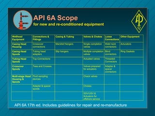
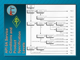
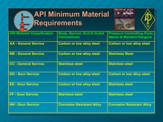
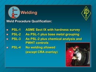
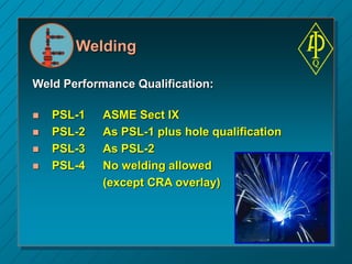
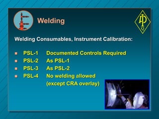
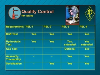
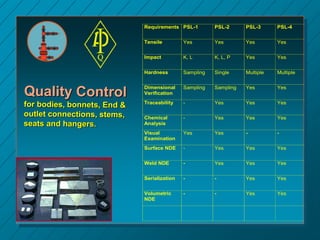
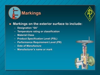
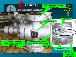
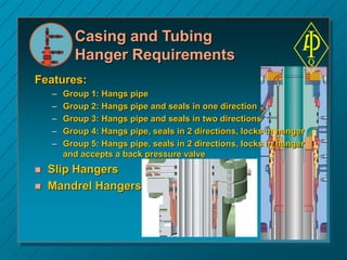
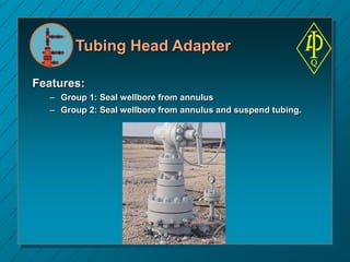
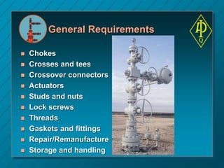
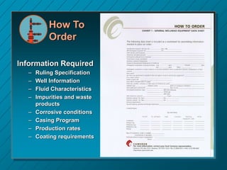
API 6A Overview
API 6A Specification for
Wellhead and Christmas Tree
Equipment
 Scope
 Service Conditions
 Product Specification Levels
 Performance Requirement Levels
 Material Class Levels
 Temperature Classes
 Specific Component Design Requirements
 Quality Control Requirements
 Valve Testing
 Casing and Tubing Hanger Requirements
 Tubing Head Adapter requirements
API 6A Scope
for new and re-conditioned equipment
Wellhead
Equipment
Connections &
Fittings
Casing & Tubing Valves & Chokes Loose
Connections
Other Equipment
Casing Head
Housing
Crossover
connections
Mandrel Hangers Single completion
valves
Weld neck
connectors
Acturators
Casing Head
Spools
Tubing head
adapters
Slip hangers Multiple completion
valves
Blind
connectors
Ring Gaskets
Tubing Head
Spools
Top Connections Actuated valves Threaded
Connectors
Crossover
Spools
Tees and Crosses Valves prepared
for actuators
Adapter &
spacer
connectors
Multi-stage Head
Housing &
Spools
Fluid sampling
devices
Check valves
Adapter & spacer
spools
Chokes
SSV/USV &
Actuators for
offshore service
API 6A 17th ed. Includes guidelines for repair and re-manufacture
API Monogram
The presence of an API monogram on wellhead
and Christmas tree equipment:
– Ensures that the materials used have been tested and
qualified to an industry accepted standard.
– Certifies a performance verification level.
– Confirms that manufacturing facilities and processes have
been audited by the recognized industry standards
organization.
– Recognizes manufacturer’s ability to produce products
suitable for the oil and gas industry.
Pressure Ratings
API Pressure Test Presure
Rating (psi) 13-3/8” 16-3/4 “
 2,000 4,000 3,000
 3,000 6,000 4,500
 5,000 10,000 10,000
 10,000 15,000 15,000
 15,000 22,500 22,500
 20,000 30,000 -
Six pressure ratings from 2,000 to 20,000 psi :
Temperature Ratings
Eight temperature ratings:
API Temp. Class’n Operating Range (° F) (°C)
K -75 to 180 -60 to 82
L -50 to 180 -46 to 82
P -20 to 180 -29 to 82
R Room Temp
S 0 to 150 -18 to 65
T 0 to 120 -18 to 50
U 0 to 250 -18 to 121
V 35 to 250 0 to 121
X 0 to 350 (app G) -18 to 180
Y 0 to 650 (app G) 18 to 345
Factors influencing the corrosivity of a well fluid:
 Temperature
 Pressure
 Production Rate
 CO2 content
 H2S content
 pH
 Sand Production
 Composition/amount of hydrocarbons
 Composition/amount of produced water/condensate
 Presence of sulfate reduction bacteria
API 6A : " choosing material classes is the
ultimate responsibility of the user "
API Material Classes
( Trim Selection )
 Use of packer/completion
fluids
 Acidizing
 Inhibition
 Chemical Injection for
hydrate control, paraffin
control, etc...
API Material Classes
( for Production Trees )
API Material
Classification
H2S partial
pressure
CO2 partial
pressure
Chlorides
content
Maximum
temperature
AA - General Service
Non-corrosive
0.05 psi < 7 psi < 20,000 ppm 350°F / 180°C
BB - General Service
Mildly corrosive
0.05 psi 7 to 30 psi < 20,000 ppm 350°F / 180°C
CC - General Service
Corrosive
0.05 psi > 30 psi < 50,000 ppm 250°F / 120°C
DD - Sour Service
Non-corrosive
> 0.05 psi < 7 psi < 20,000 ppm 350°F / 180°C
EE - Sour Service
Mildly corrosive
> 0.05 psi 7 to 30 psi < 50,000 ppm 350°F / 180°C
FF - Sour Service
Corrosive
> 0.05 psi > 30 psi < 50,000 ppm 250°F / 120°C
HH - Sour Service
Extremely corrosive
> 10 psi > 30 psi < 100,000 ppm 350°F / 180°C
API Minimum Material
Requirements
API Material Classification Body, Bonnet, End & Outlet
Connections
Pressure Controlling Parts,
Stems & Mandrel Hangers
AA - General Service Carbon or low alloy steel Carbon or low alloy steel
BB - General Service Carbon or low alloy steel Stainless Steel
CC - General Service Stainless steel Stainless steel
DD - Sour Service Carbon or low alloy steel Carbon or low alloy steel
EE - Sour Service Carbon or low alloy steel Stainless steel
FF - Sour Service Stainless steel Stainless steel
HH - Sour Service Corrosion Resistant Alloy Corrosion Resistant Alloy
Welding
Weld Procedure Qualification:
 PSL-1 ASME Sect IX with hardness survey
 PSL-2 As PSL-1 plus base metal grouping
 PSL-3 As PSL-2 plus chemical analysis and
PWHT controls
 PSL-4 No welding allowed
(except CRA overlay)
Welding
Weld Performance Qualification:
 PSL-1 ASME Sect IX
 PSL-2 As PSL-1 plus hole qualification
 PSL-3 As PSL-2
 PSL-4 No welding allowed
(except CRA overlay)
Welding
Welding Consumables, Instrument Calibration:
 PSL-1 Documented Controls Required
 PSL-2 As PSL-1
 PSL-3 As PSL-2
 PSL-4 No welding allowed
(except CRA overlay)
Welding
Visual Exam of Weld :
 PSL-1 -
 PSL-2 Required
 PSL-3 Required
 PSL-4 No welding allowed
(except CRA overlay)
Welding
Surface NDE: PT/MT:
 PSL-1 -
 PSL-2 Required
 PSL-3 Required
 PSL-4 No welding allowed
(except CRA overlay)
PT - Liquid Penetrant
MT - Magnetic
Welding
Weld Volumetric NDE: UT/RT:
 PSL-1 -
 PSL-2 Required for all fabrication welds
and repair welds > 25% wall
 PSL-3 Required for all fabrication welds
and repair welds > 20% wall
 PSL-4 No welding allowed
(except CRA overlay)
UT - Ultrasonic Testing
RT - Radiographic Testing
Welding
Weld Hardness Testing:
 PSL-1 -
 PSL-2 -
 PSL-3 Required
 PSL-4 No welding allowed
(except CRA overlay)
Quality Control
for valves
Requirements PSL-1 PSL-2 PSL-3 PSL-4
Drift Test Yes Yes Yes Yes
Hydrostatic
Test
Yes Yes Yes,
extended
Yes
extended
Gas Test - - Optional Yes
Assembly
Traceability
- - Yes Yes
Serialization - Yes Yes Yes
Requirements PSL-1 PSL-2 PSL-3 PSL-4
Tensile Yes Yes Yes Yes
Impact K, L K, L, P Yes Yes
Hardness Sampling Single Multiple Multiple
Dimensional
Verification
Sampling Sampling Yes Yes
Traceability - Yes Yes Yes
Chemical
Analysis
- Yes Yes Yes
Visual
Examination
Yes Yes - -
Surface NDE - Yes Yes Yes
Weld NDE - Yes Yes Yes
Serialization - - Yes Yes
Volumetric
NDE
- - Yes Yes
Markings
 Markings on the exterior surface to include:
– Designation “6A”
– Temperature rating or classification
– Material Class
– Product Specification Level (PSL)
– Performance Requirement Level (PR)
– Date of Manufacture
– Manufacturer’s name or mark
BODY MARKING: P/N, REV,
MFG.ID, S/N
GV ASSEMBLY MARKING:
"ASSY", P/N, REV, MFG.ID
("CCF"), S/N
GV NAMEPLATE
API 6A INFORMATION:
SIZE, WP, M/C, T/C, PSL, PR
API 6A LOGO
STAMP WITH
LICENSEE N°
ASSY S/N
ASSY P/N
CAMERON LOGO
GV Identification
Valve Testing
Hydrostatic Testing
– Body test to 1.5 or 2 times WP (depending on
size)
– Seat test to WP
– Chart recording for PSL 3 and 4
Gas Testing
– No bubbles observed, (less than 20 cm3/hour)
– All potential leak paths submerged, Nitrogen
as test medium
– Body test for 15 minute hold period
– Seat test for 60 minute hold period
– Test pressure is working pressure (WP)
– Backseat test (WP)
Requirements PSL-1 PSL-2 PSL-3 PSL-4
Hydrostatic
Body Test
1.5 to 2x
WP, 2x 3’
1.5 to 2x
WP, 2x 3’
1.5 to 2x WP,
3’ + 15’
1.5 to 2x
WP, 3’ + 15’
Hydrostatic Seat
Test
WP, 2x 3’
per seat
WP, 3x 3’
per seat
WP, 3’ + 2x 15’
per seat
WP, 3’ + 2x
15’ per seat
P opening N/A 2 per seat 2 per seat 2 per seat
Gas Body Test - - Opt., WP, 15’ WP, 15’
Gas Seat Test
(per seat)
- - Opt., 15’ at WP
+ 15’ at 300 psi
60’ at WP +
60’ at 5-
10% WP
Gas Backseat
Test
- - Opt., WP, 15’ WP, 2x 60’
Valve Testing (holding time)
Xmas tree Testing
Drift Testing
– Through main bore (vertical)
– 42'' - 1065 mm long drift
– PSL 1 to 4
Hydrostatic Testing
– Body test to WP (if with previously tested
equipment)
– Hold period per PSL (2x 3' or 3' + 15')
– No mandatory seat test if previously done on
individual valves
Valve Testing
Appendix F Performance Requirements
PR level PR-1 PR-2
Open/Close dynamic
pressure test - room temp
3 cycles 160 cycles
Low Pressure seat test -
room temp
Objective evidence I hour at 5- 10% WP
Open/Close dynamic
pressure test - max/tin temp
Objective evidence 20 cycles at each extreme
Low Pressure seat test - min
temp
Objective evidence I hour at 5- 10%
Fluid compatibility Objective evidence Yes
Operating Force Per Manufacturer's spec Yes
Press/Temp cycling Objective evidence Yes
Casing and Tubing
Hanger Requirements
Features:
– Group 1: Hangs pipe
– Group 2: Hangs pipe and seals in one direction
– Group 3: Hangs pipe and seals in two directions
– Group 4: Hangs pipe, seals in 2 directions, locks in hanger
– Group 5: Hangs pipe, seals in 2 directions, locks in hanger
and accepts a back pressure valve
 Slip Hangers
 Mandrel Hangers
Tubing Head Adapter
Features:
– Group 1: Seal wellbore from annulus
– Group 2: Seal wellbore from annulus and suspend tubing.
General Requirements
 Chokes
 Crosses and tees
 Crossover connectors
 Actuators
 Studs and nuts
 Lock screws
 Threads
 Gaskets and fittings
 Repair/Remanufacture
 Storage and handling
How To
Order
Information Required
– Ruling Specification
– Well Information
– Fluid Characteristics
– Impurities and waste
products
– Corrosive conditions
– Casing Program
– Production rates
– Coating requirements
API 6A Summary
 Standard for wellhead industry
 Covers wellheads, hangers, valves, flanges
 Use for design, material selection, manufacture,
fabrication and testing
 Deviations from standard cost money and time

API 6A Wellhead Selection.ppt

  • 1.
  • 2.
    API 6A Specificationfor Wellhead and Christmas Tree Equipment  Scope  Service Conditions  Product Specification Levels  Performance Requirement Levels  Material Class Levels  Temperature Classes  Specific Component Design Requirements  Quality Control Requirements  Valve Testing  Casing and Tubing Hanger Requirements  Tubing Head Adapter requirements
  • 3.
    API 6A Scope fornew and re-conditioned equipment Wellhead Equipment Connections & Fittings Casing & Tubing Valves & Chokes Loose Connections Other Equipment Casing Head Housing Crossover connections Mandrel Hangers Single completion valves Weld neck connectors Acturators Casing Head Spools Tubing head adapters Slip hangers Multiple completion valves Blind connectors Ring Gaskets Tubing Head Spools Top Connections Actuated valves Threaded Connectors Crossover Spools Tees and Crosses Valves prepared for actuators Adapter & spacer connectors Multi-stage Head Housing & Spools Fluid sampling devices Check valves Adapter & spacer spools Chokes SSV/USV & Actuators for offshore service API 6A 17th ed. Includes guidelines for repair and re-manufacture
  • 4.
    API Monogram The presenceof an API monogram on wellhead and Christmas tree equipment: – Ensures that the materials used have been tested and qualified to an industry accepted standard. – Certifies a performance verification level. – Confirms that manufacturing facilities and processes have been audited by the recognized industry standards organization. – Recognizes manufacturer’s ability to produce products suitable for the oil and gas industry.
  • 6.
    Pressure Ratings API PressureTest Presure Rating (psi) 13-3/8” 16-3/4 “  2,000 4,000 3,000  3,000 6,000 4,500  5,000 10,000 10,000  10,000 15,000 15,000  15,000 22,500 22,500  20,000 30,000 - Six pressure ratings from 2,000 to 20,000 psi :
  • 7.
    Temperature Ratings Eight temperatureratings: API Temp. Class’n Operating Range (° F) (°C) K -75 to 180 -60 to 82 L -50 to 180 -46 to 82 P -20 to 180 -29 to 82 R Room Temp S 0 to 150 -18 to 65 T 0 to 120 -18 to 50 U 0 to 250 -18 to 121 V 35 to 250 0 to 121 X 0 to 350 (app G) -18 to 180 Y 0 to 650 (app G) 18 to 345
  • 8.
    Factors influencing thecorrosivity of a well fluid:  Temperature  Pressure  Production Rate  CO2 content  H2S content  pH  Sand Production  Composition/amount of hydrocarbons  Composition/amount of produced water/condensate  Presence of sulfate reduction bacteria API 6A : " choosing material classes is the ultimate responsibility of the user " API Material Classes ( Trim Selection )  Use of packer/completion fluids  Acidizing  Inhibition  Chemical Injection for hydrate control, paraffin control, etc...
  • 9.
    API Material Classes (for Production Trees ) API Material Classification H2S partial pressure CO2 partial pressure Chlorides content Maximum temperature AA - General Service Non-corrosive 0.05 psi < 7 psi < 20,000 ppm 350°F / 180°C BB - General Service Mildly corrosive 0.05 psi 7 to 30 psi < 20,000 ppm 350°F / 180°C CC - General Service Corrosive 0.05 psi > 30 psi < 50,000 ppm 250°F / 120°C DD - Sour Service Non-corrosive > 0.05 psi < 7 psi < 20,000 ppm 350°F / 180°C EE - Sour Service Mildly corrosive > 0.05 psi 7 to 30 psi < 50,000 ppm 350°F / 180°C FF - Sour Service Corrosive > 0.05 psi > 30 psi < 50,000 ppm 250°F / 120°C HH - Sour Service Extremely corrosive > 10 psi > 30 psi < 100,000 ppm 350°F / 180°C
  • 10.
    API Minimum Material Requirements APIMaterial Classification Body, Bonnet, End & Outlet Connections Pressure Controlling Parts, Stems & Mandrel Hangers AA - General Service Carbon or low alloy steel Carbon or low alloy steel BB - General Service Carbon or low alloy steel Stainless Steel CC - General Service Stainless steel Stainless steel DD - Sour Service Carbon or low alloy steel Carbon or low alloy steel EE - Sour Service Carbon or low alloy steel Stainless steel FF - Sour Service Stainless steel Stainless steel HH - Sour Service Corrosion Resistant Alloy Corrosion Resistant Alloy
  • 11.
    Welding Weld Procedure Qualification: PSL-1 ASME Sect IX with hardness survey  PSL-2 As PSL-1 plus base metal grouping  PSL-3 As PSL-2 plus chemical analysis and PWHT controls  PSL-4 No welding allowed (except CRA overlay)
  • 12.
    Welding Weld Performance Qualification: PSL-1 ASME Sect IX  PSL-2 As PSL-1 plus hole qualification  PSL-3 As PSL-2  PSL-4 No welding allowed (except CRA overlay)
  • 13.
    Welding Welding Consumables, InstrumentCalibration:  PSL-1 Documented Controls Required  PSL-2 As PSL-1  PSL-3 As PSL-2  PSL-4 No welding allowed (except CRA overlay)
  • 14.
    Welding Visual Exam ofWeld :  PSL-1 -  PSL-2 Required  PSL-3 Required  PSL-4 No welding allowed (except CRA overlay)
  • 15.
    Welding Surface NDE: PT/MT: PSL-1 -  PSL-2 Required  PSL-3 Required  PSL-4 No welding allowed (except CRA overlay) PT - Liquid Penetrant MT - Magnetic
  • 16.
    Welding Weld Volumetric NDE:UT/RT:  PSL-1 -  PSL-2 Required for all fabrication welds and repair welds > 25% wall  PSL-3 Required for all fabrication welds and repair welds > 20% wall  PSL-4 No welding allowed (except CRA overlay) UT - Ultrasonic Testing RT - Radiographic Testing
  • 17.
    Welding Weld Hardness Testing: PSL-1 -  PSL-2 -  PSL-3 Required  PSL-4 No welding allowed (except CRA overlay)
  • 18.
    Quality Control for valves RequirementsPSL-1 PSL-2 PSL-3 PSL-4 Drift Test Yes Yes Yes Yes Hydrostatic Test Yes Yes Yes, extended Yes extended Gas Test - - Optional Yes Assembly Traceability - - Yes Yes Serialization - Yes Yes Yes
  • 19.
    Requirements PSL-1 PSL-2PSL-3 PSL-4 Tensile Yes Yes Yes Yes Impact K, L K, L, P Yes Yes Hardness Sampling Single Multiple Multiple Dimensional Verification Sampling Sampling Yes Yes Traceability - Yes Yes Yes Chemical Analysis - Yes Yes Yes Visual Examination Yes Yes - - Surface NDE - Yes Yes Yes Weld NDE - Yes Yes Yes Serialization - - Yes Yes Volumetric NDE - - Yes Yes
  • 20.
    Markings  Markings onthe exterior surface to include: – Designation “6A” – Temperature rating or classification – Material Class – Product Specification Level (PSL) – Performance Requirement Level (PR) – Date of Manufacture – Manufacturer’s name or mark
  • 21.
    BODY MARKING: P/N,REV, MFG.ID, S/N GV ASSEMBLY MARKING: "ASSY", P/N, REV, MFG.ID ("CCF"), S/N GV NAMEPLATE API 6A INFORMATION: SIZE, WP, M/C, T/C, PSL, PR API 6A LOGO STAMP WITH LICENSEE N° ASSY S/N ASSY P/N CAMERON LOGO GV Identification
  • 22.
    Valve Testing Hydrostatic Testing –Body test to 1.5 or 2 times WP (depending on size) – Seat test to WP – Chart recording for PSL 3 and 4 Gas Testing – No bubbles observed, (less than 20 cm3/hour) – All potential leak paths submerged, Nitrogen as test medium – Body test for 15 minute hold period – Seat test for 60 minute hold period – Test pressure is working pressure (WP) – Backseat test (WP)
  • 23.
    Requirements PSL-1 PSL-2PSL-3 PSL-4 Hydrostatic Body Test 1.5 to 2x WP, 2x 3’ 1.5 to 2x WP, 2x 3’ 1.5 to 2x WP, 3’ + 15’ 1.5 to 2x WP, 3’ + 15’ Hydrostatic Seat Test WP, 2x 3’ per seat WP, 3x 3’ per seat WP, 3’ + 2x 15’ per seat WP, 3’ + 2x 15’ per seat P opening N/A 2 per seat 2 per seat 2 per seat Gas Body Test - - Opt., WP, 15’ WP, 15’ Gas Seat Test (per seat) - - Opt., 15’ at WP + 15’ at 300 psi 60’ at WP + 60’ at 5- 10% WP Gas Backseat Test - - Opt., WP, 15’ WP, 2x 60’ Valve Testing (holding time)
  • 24.
    Xmas tree Testing DriftTesting – Through main bore (vertical) – 42'' - 1065 mm long drift – PSL 1 to 4 Hydrostatic Testing – Body test to WP (if with previously tested equipment) – Hold period per PSL (2x 3' or 3' + 15') – No mandatory seat test if previously done on individual valves
  • 25.
    Valve Testing Appendix FPerformance Requirements PR level PR-1 PR-2 Open/Close dynamic pressure test - room temp 3 cycles 160 cycles Low Pressure seat test - room temp Objective evidence I hour at 5- 10% WP Open/Close dynamic pressure test - max/tin temp Objective evidence 20 cycles at each extreme Low Pressure seat test - min temp Objective evidence I hour at 5- 10% Fluid compatibility Objective evidence Yes Operating Force Per Manufacturer's spec Yes Press/Temp cycling Objective evidence Yes
  • 26.
    Casing and Tubing HangerRequirements Features: – Group 1: Hangs pipe – Group 2: Hangs pipe and seals in one direction – Group 3: Hangs pipe and seals in two directions – Group 4: Hangs pipe, seals in 2 directions, locks in hanger – Group 5: Hangs pipe, seals in 2 directions, locks in hanger and accepts a back pressure valve  Slip Hangers  Mandrel Hangers
  • 27.
    Tubing Head Adapter Features: –Group 1: Seal wellbore from annulus – Group 2: Seal wellbore from annulus and suspend tubing.
  • 28.
    General Requirements  Chokes Crosses and tees  Crossover connectors  Actuators  Studs and nuts  Lock screws  Threads  Gaskets and fittings  Repair/Remanufacture  Storage and handling
  • 29.
    How To Order Information Required –Ruling Specification – Well Information – Fluid Characteristics – Impurities and waste products – Corrosive conditions – Casing Program – Production rates – Coating requirements
  • 30.
    API 6A Summary Standard for wellhead industry  Covers wellheads, hangers, valves, flanges  Use for design, material selection, manufacture, fabrication and testing  Deviations from standard cost money and time