The Machinerefers to the procedures and
techniques used to address the three phases of
a machine’s lifecycle:
- invention, which involves the identification of a
need, development of requirements, concept
generation, prototype development, manufacturing,
and verification testing;
- performance engineering involves enhancing
manufacturing efficiency, reducing service and
maintenance demands, adding features and improving
effectiveness.
- recycle is the decommissioning and disposal phase
and includes recovery and reuse of materials and
components.
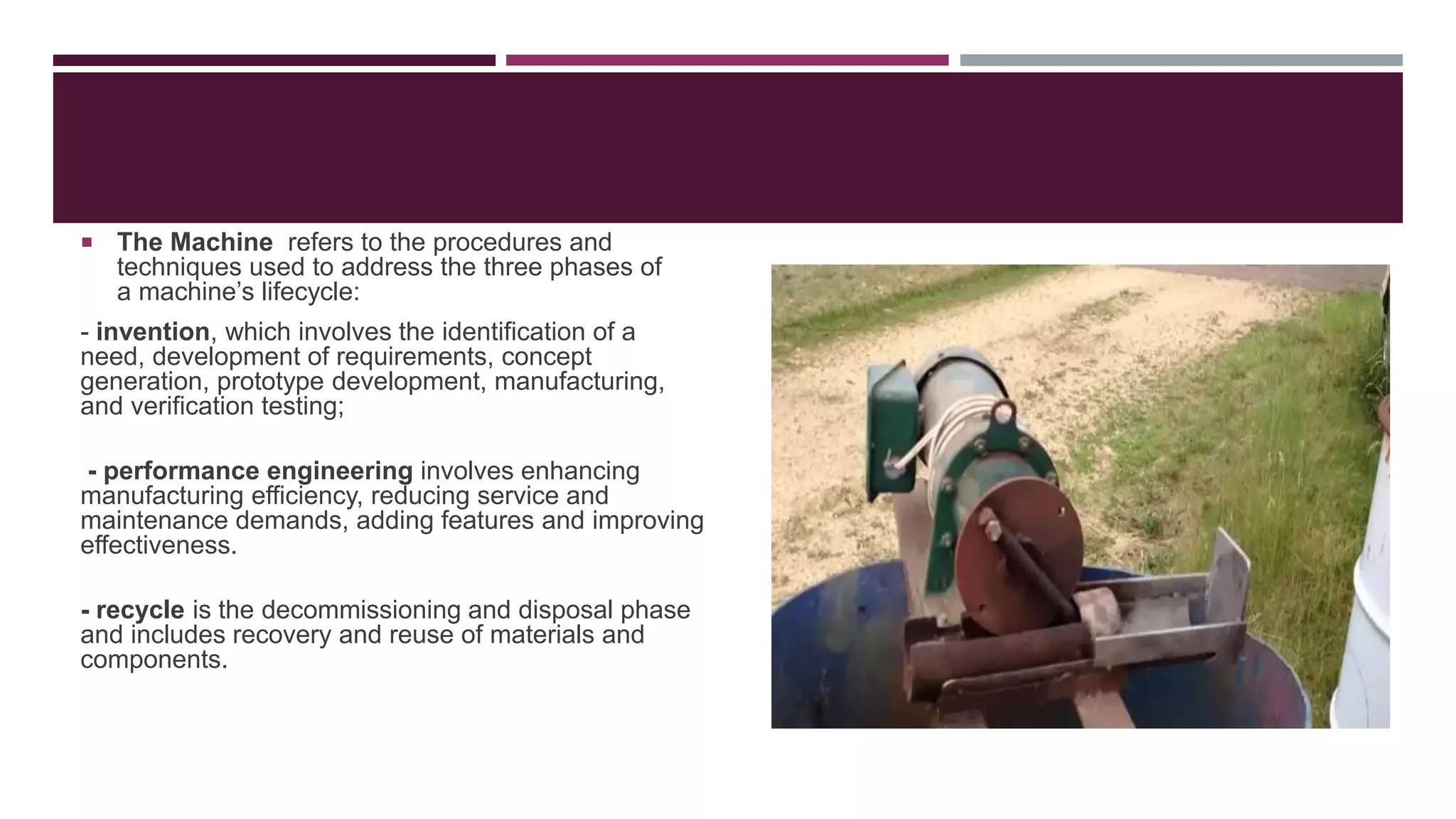
ORIGIN OF CANCRUSHER
A can crusher is an instrument used for
crushing soda cans.
This is done to make storage easier.
This provides more space in the bin.
The very first can crusher was the human
foot.
These can crushers are used in the real
world when people or companies that have
aluminum cans want to save space in the
recycling bin.
8.
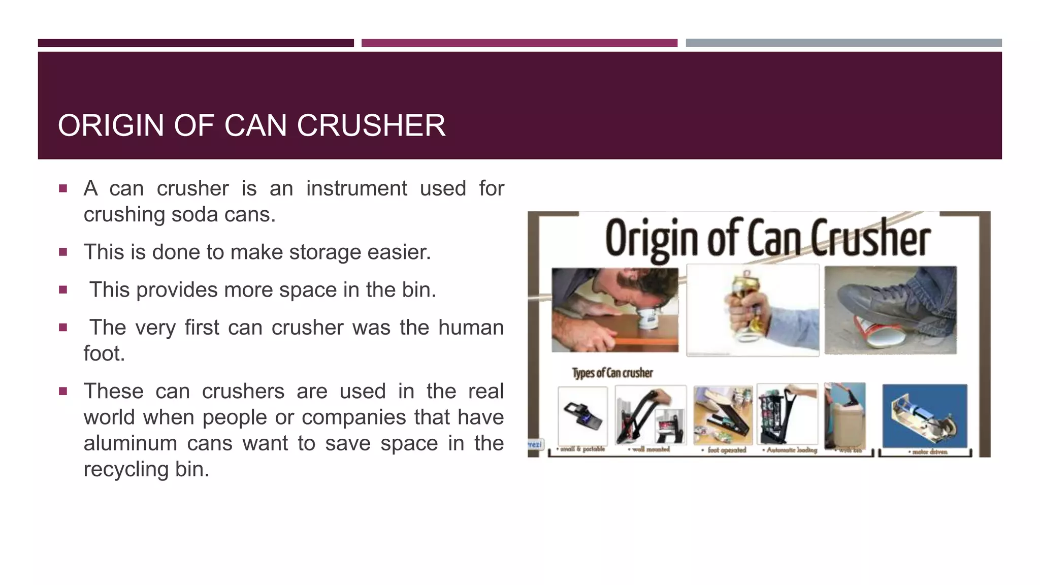
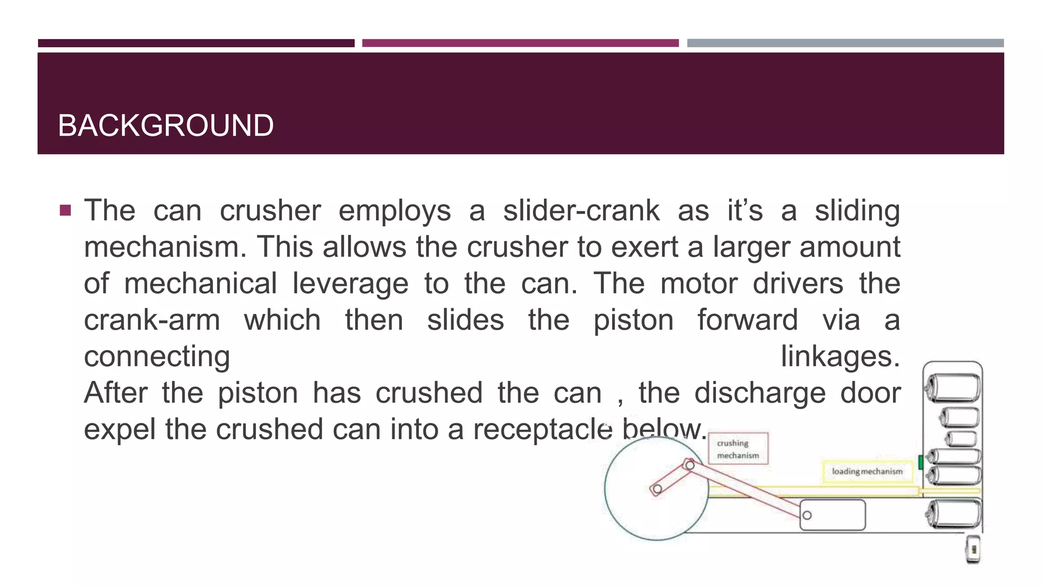
BACKGROUND
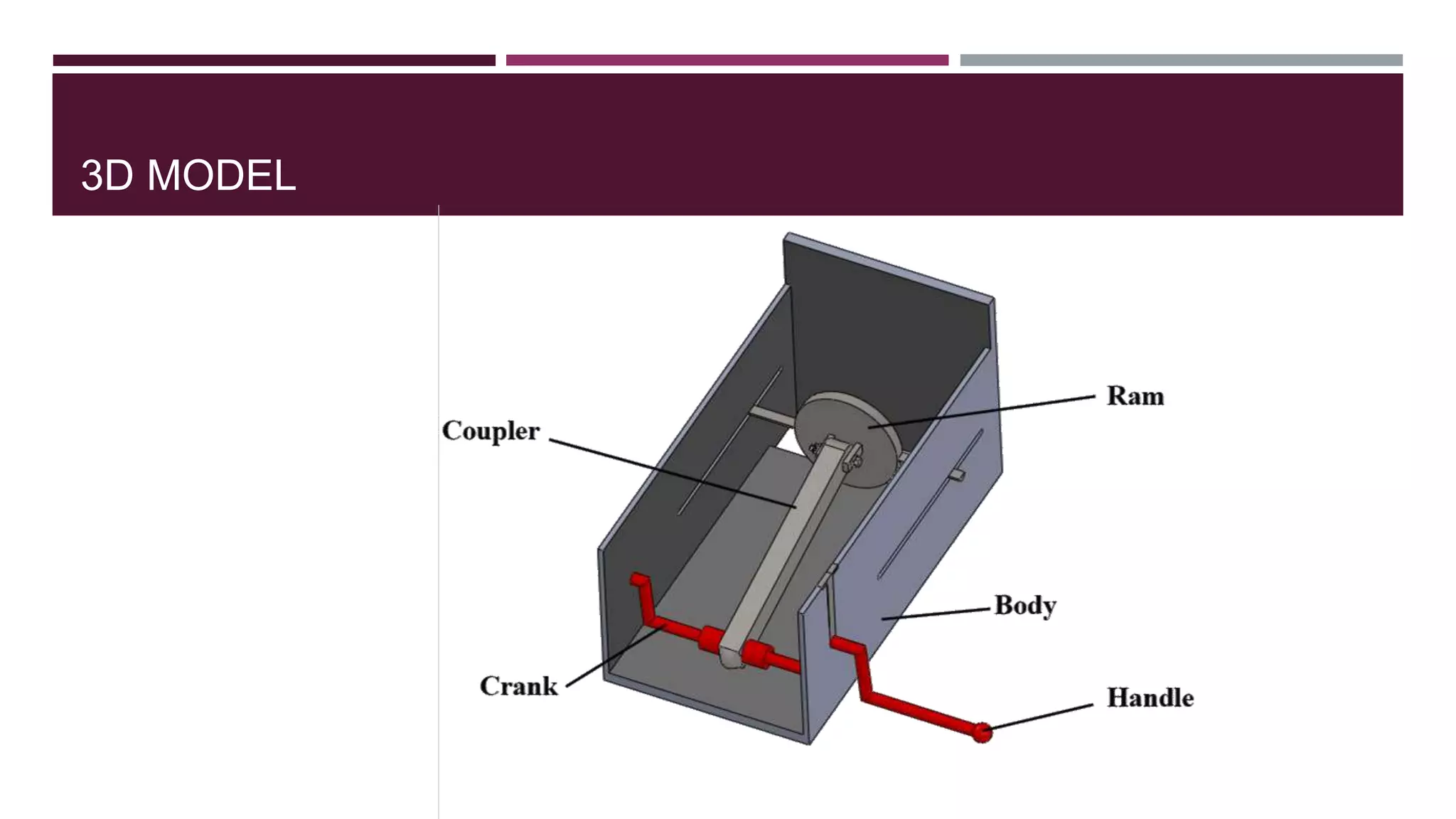
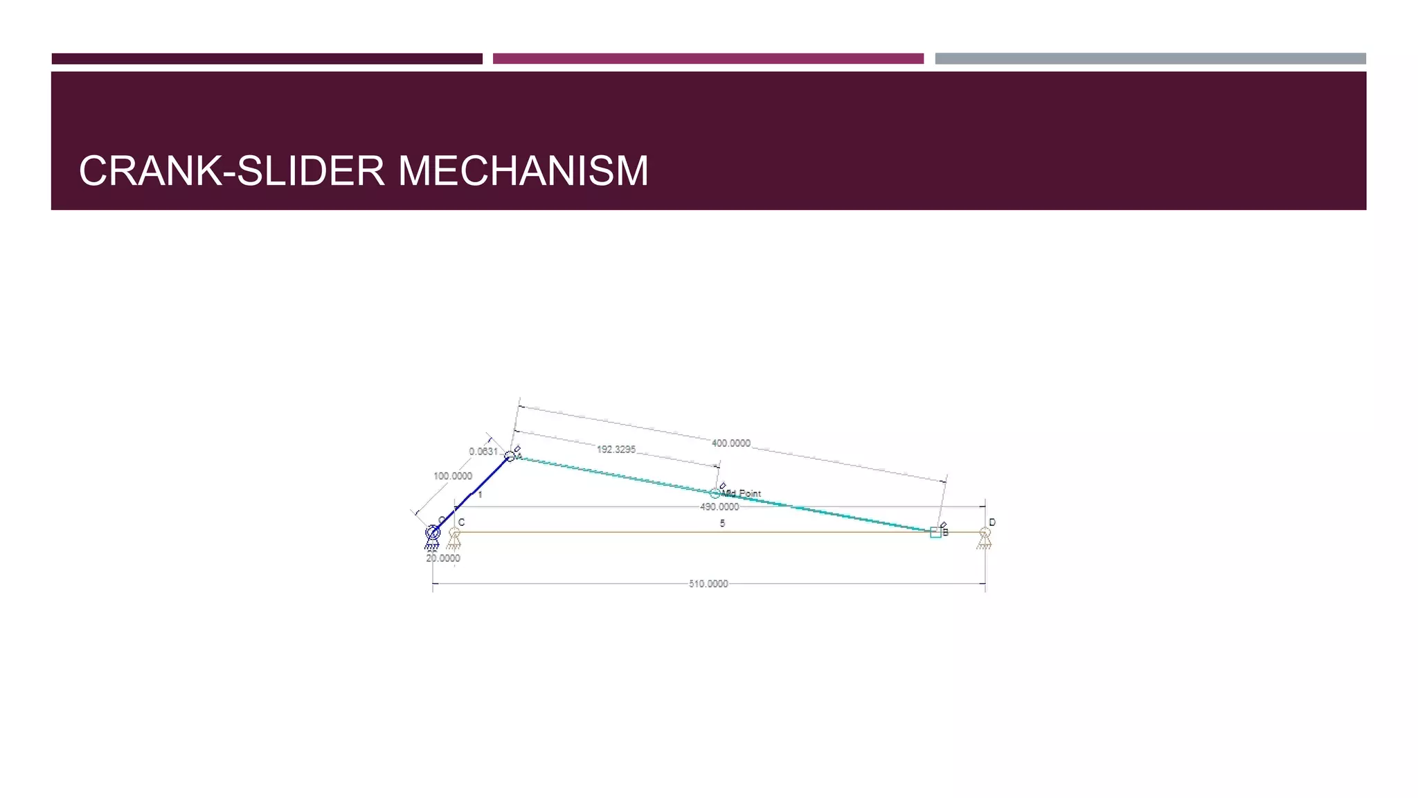
The cancrusher employs a slider-crank as it’s a sliding
mechanism. This allows the crusher to exert a larger amount
of mechanical leverage to the can. The motor drivers the
crank-arm which then slides the piston forward via a
connecting linkages.
After the piston has crushed the can , the discharge door
expel the crushed can into a receptacle below.
9.
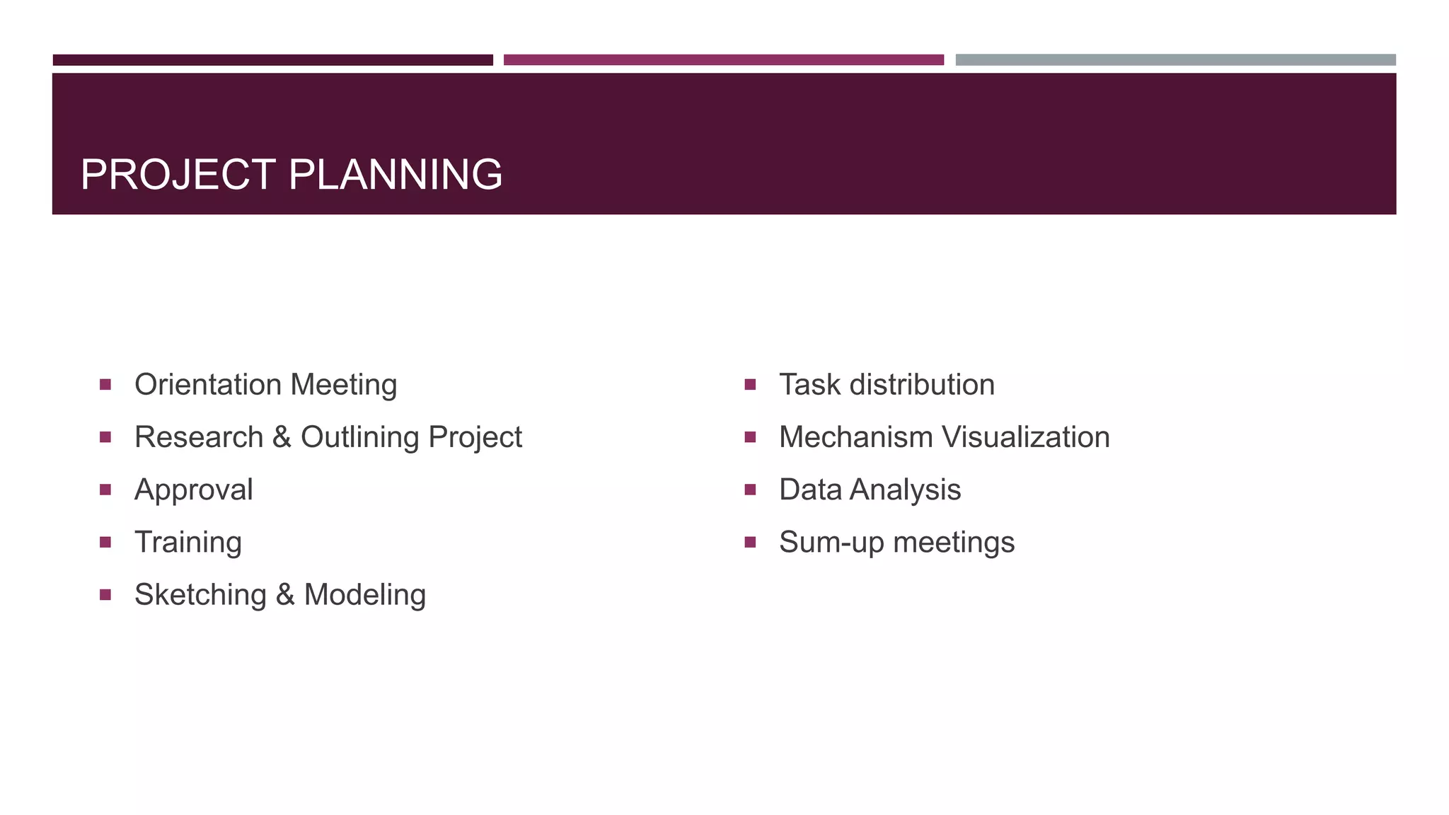
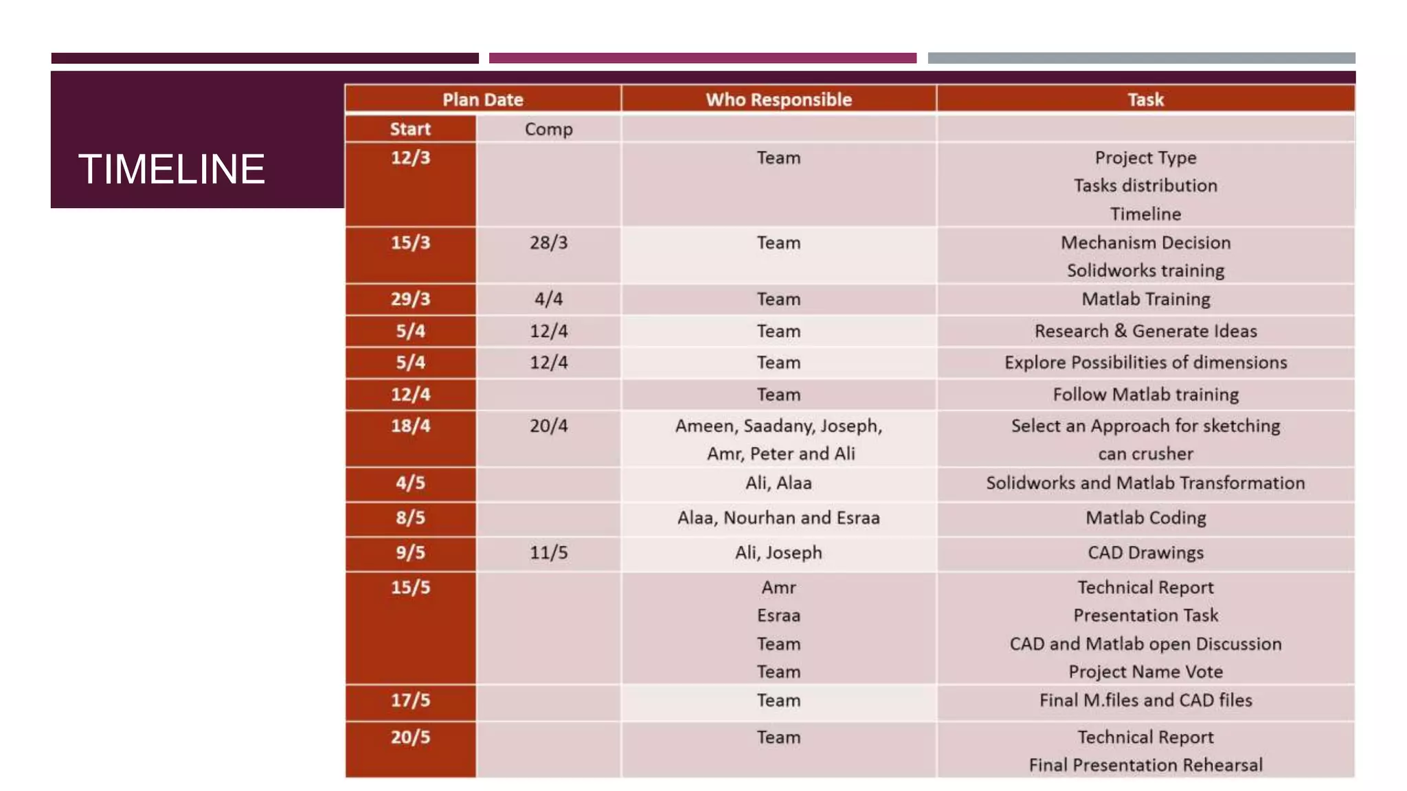
PROJECT PLANNING
OrientationMeeting
Research & Outlining Project
Approval
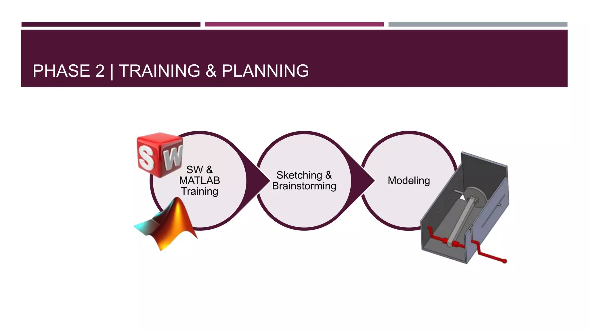
Training
Sketching & Modeling
Task distribution
Mechanism Visualization
Data Analysis
Sum-up meetings
10.
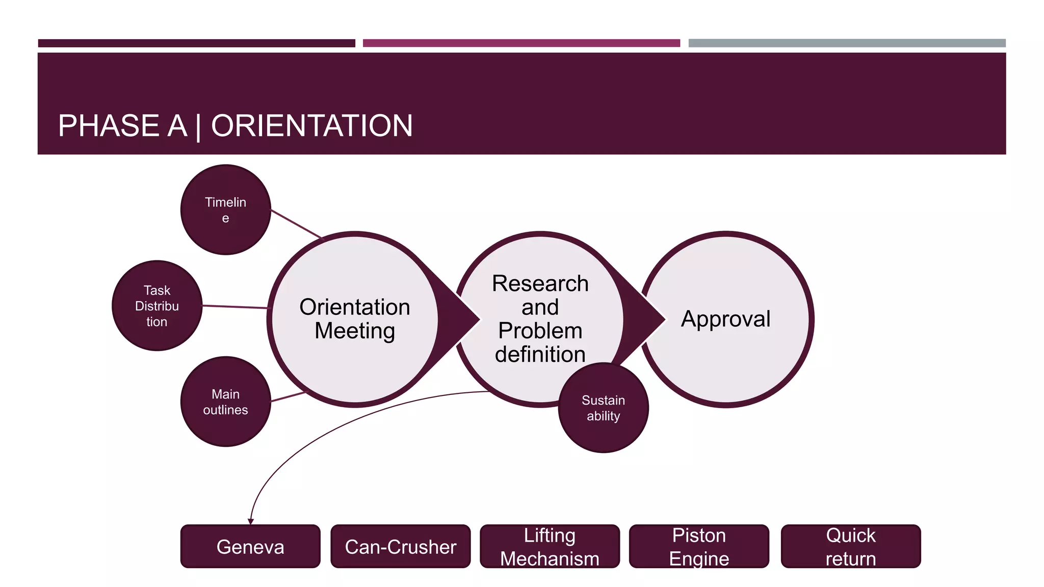
PHASE A |ORIENTATION
Approval
Research
and
Problem
definition
Orientation
Meeting
Main
outlines
Task
Distribu
tion
Timelin
e
Sustain
ability
Can-Crusher
Lifting
Mechanism
Piston
Engine
Geneva
Quick
return
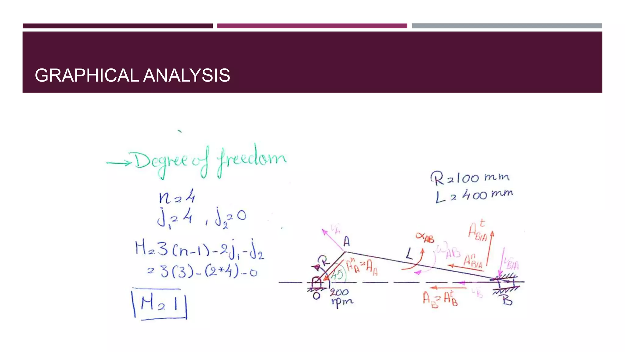
MECHANISM SYNTHESIS ANDANALYSIS
Synthesis : design a mechanism to perform a
desired function.
Analysis : given a mechanism, perform kinematics and
kinetics analysis
(Graphical techniques and Analytical methods)
16.
MECHANISM SYNTHESIS
Thedrawings are diving into two categories, which are:
1) Sketching: all the ideals for tin can crusher are sketched on the paper to
ensure that ideas selection can be made after the selected design choose.
2) Solid Works Application: The design or concept sketched is transfer to solid
modeling and drawing using Solid Work Application.
17.
1) Sketching:
all theideals for tin can crusher are sketched on the paper
to ensure that ideas selection can be made after the selected design choose.
Explore Possibilities
Select an Approach
Develop a Design Proposal
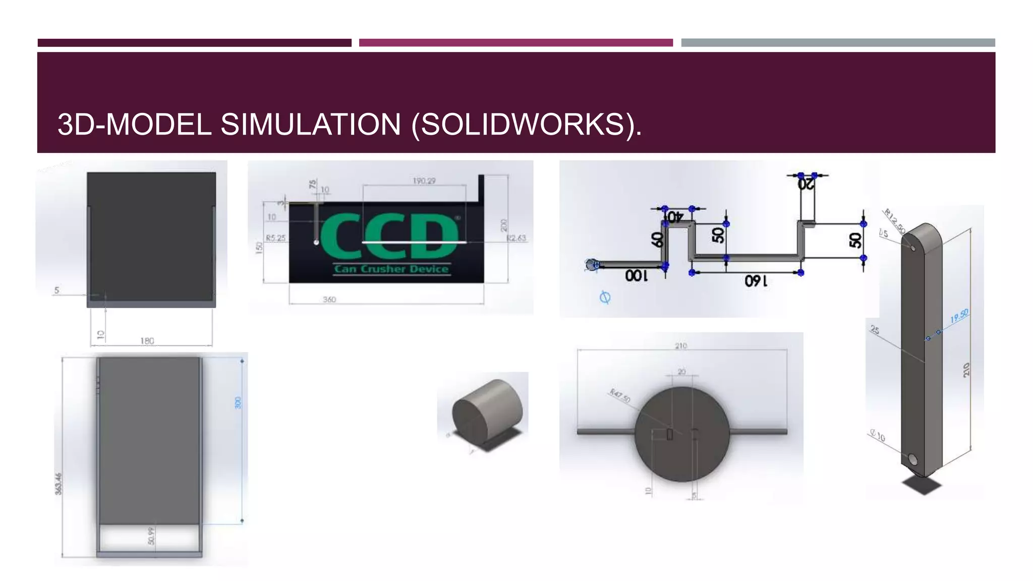
2) Simulating the 3D Model | Criteria and Constraints
Maximum space: 200x350x180 mm
Volume must be 70% less than originally
At least 1 simple machine
Manually operated
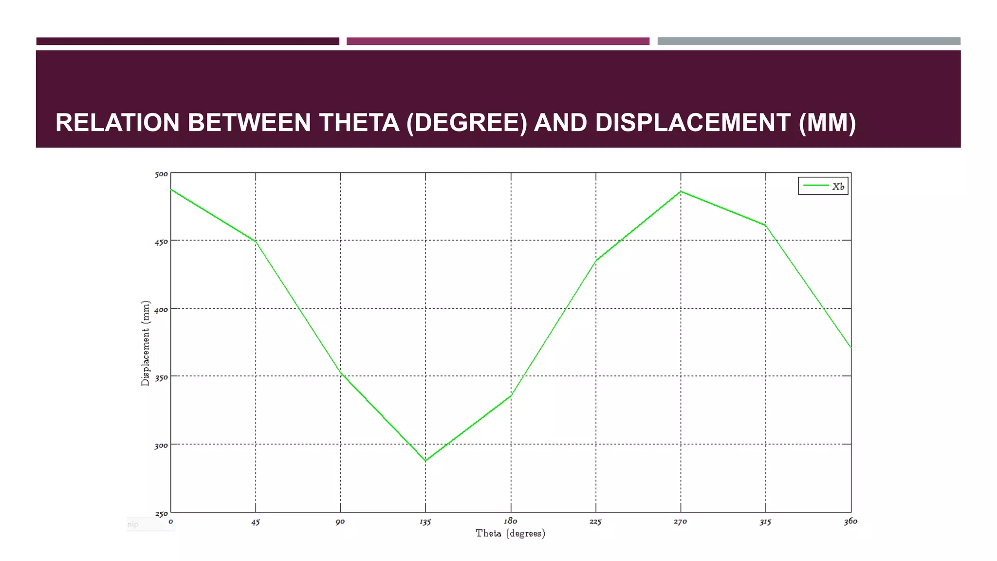
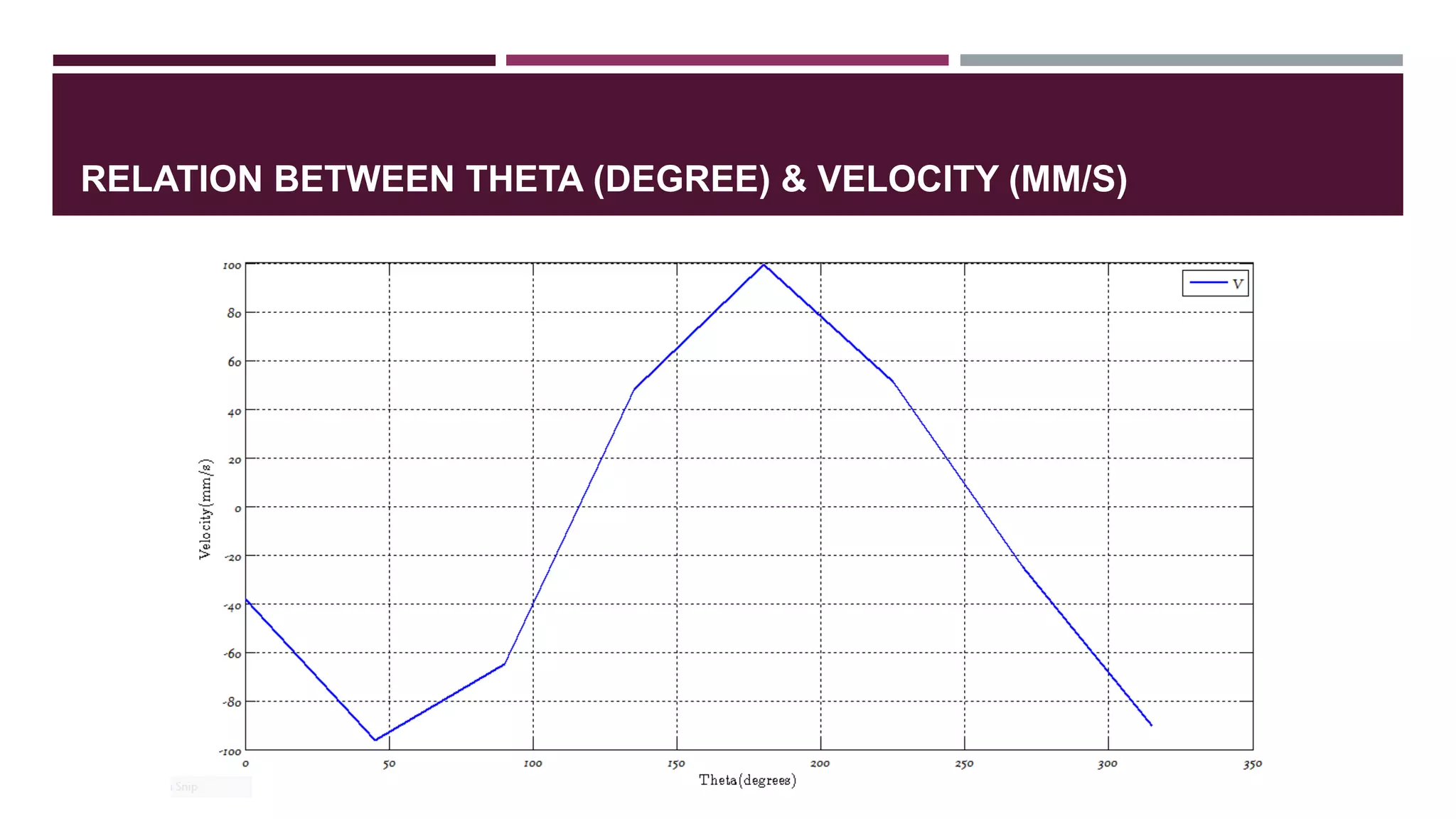
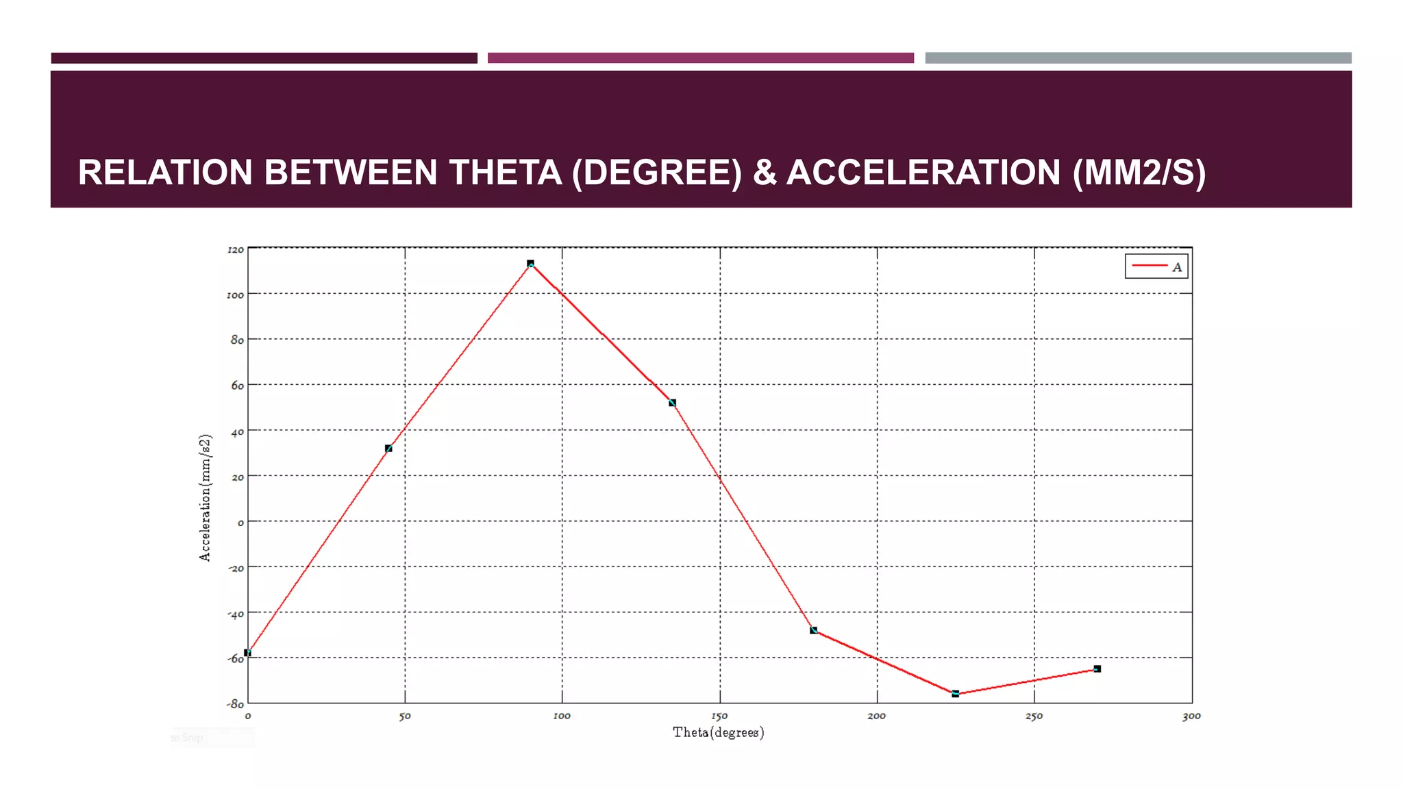
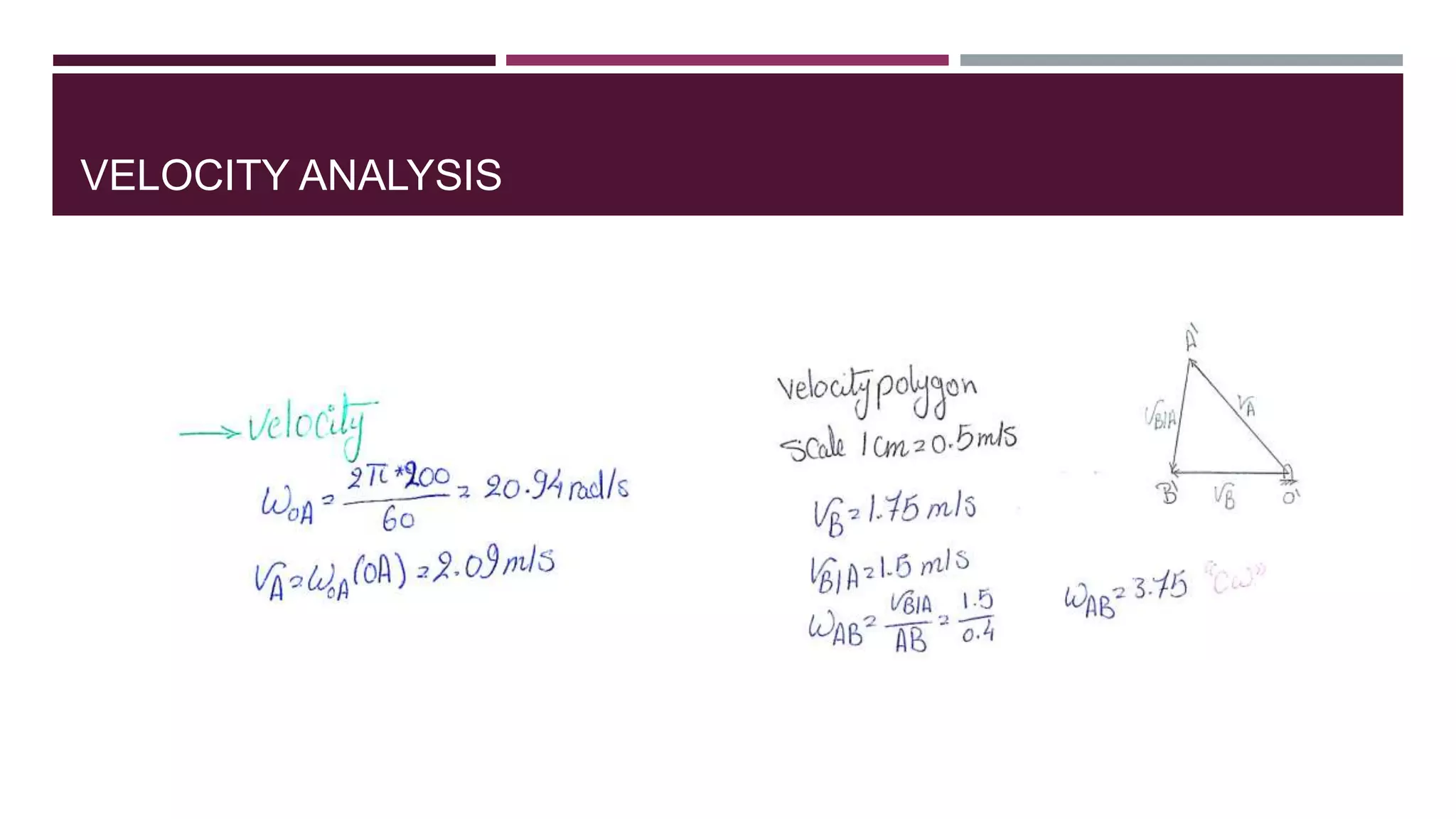
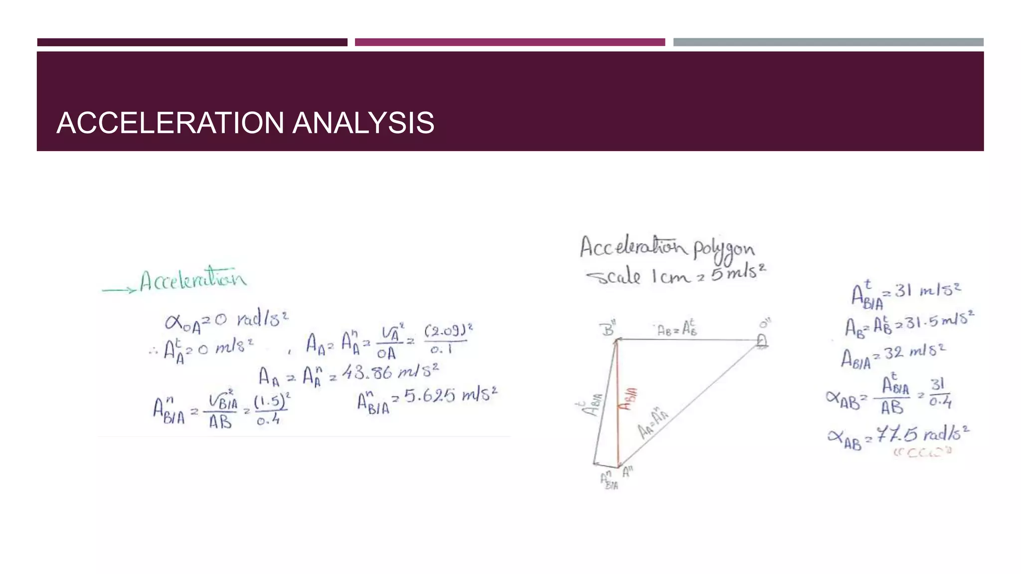
MECHANISM MOTION ANALYSIS
Itis divided into two categories, which are:
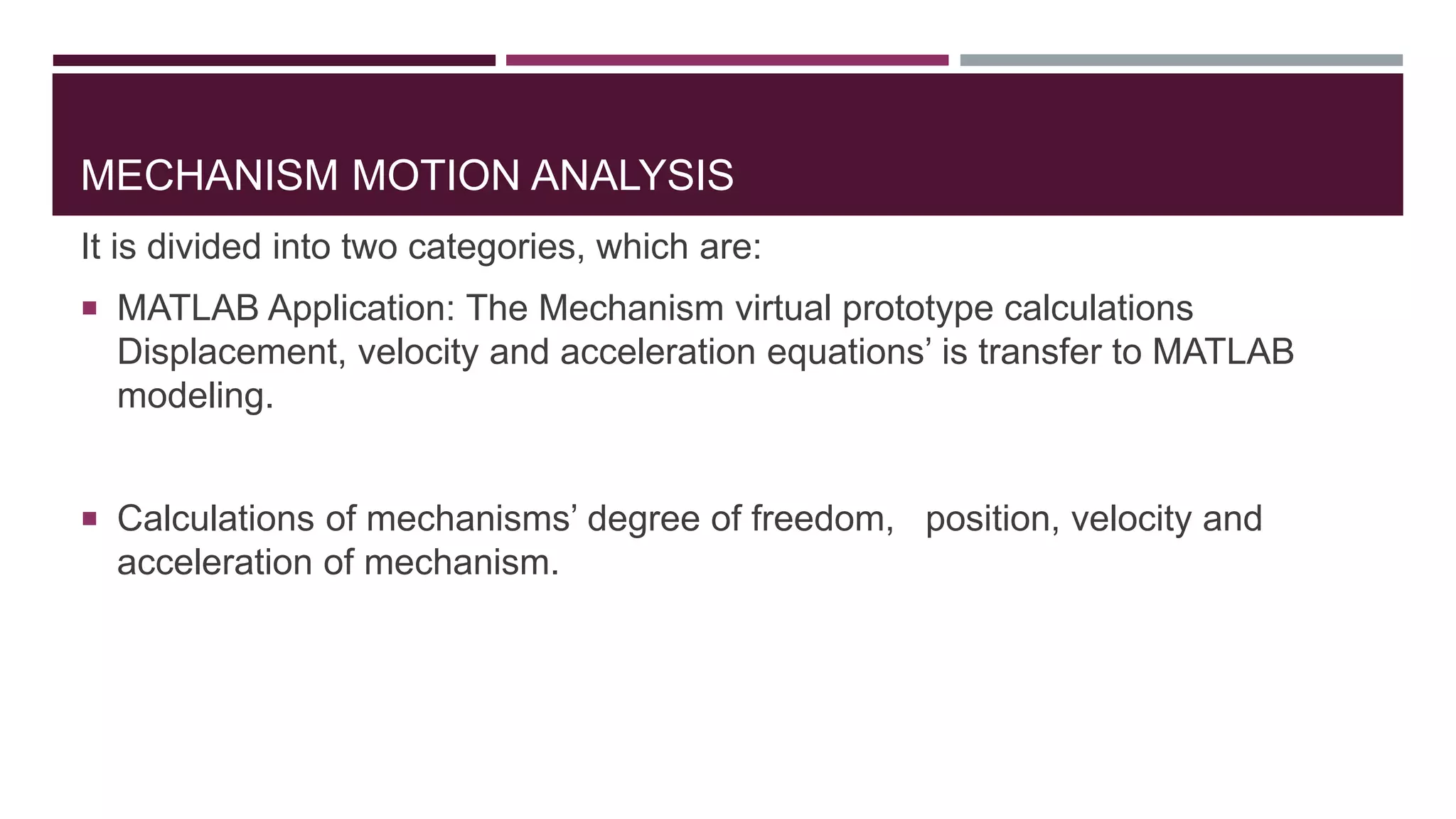
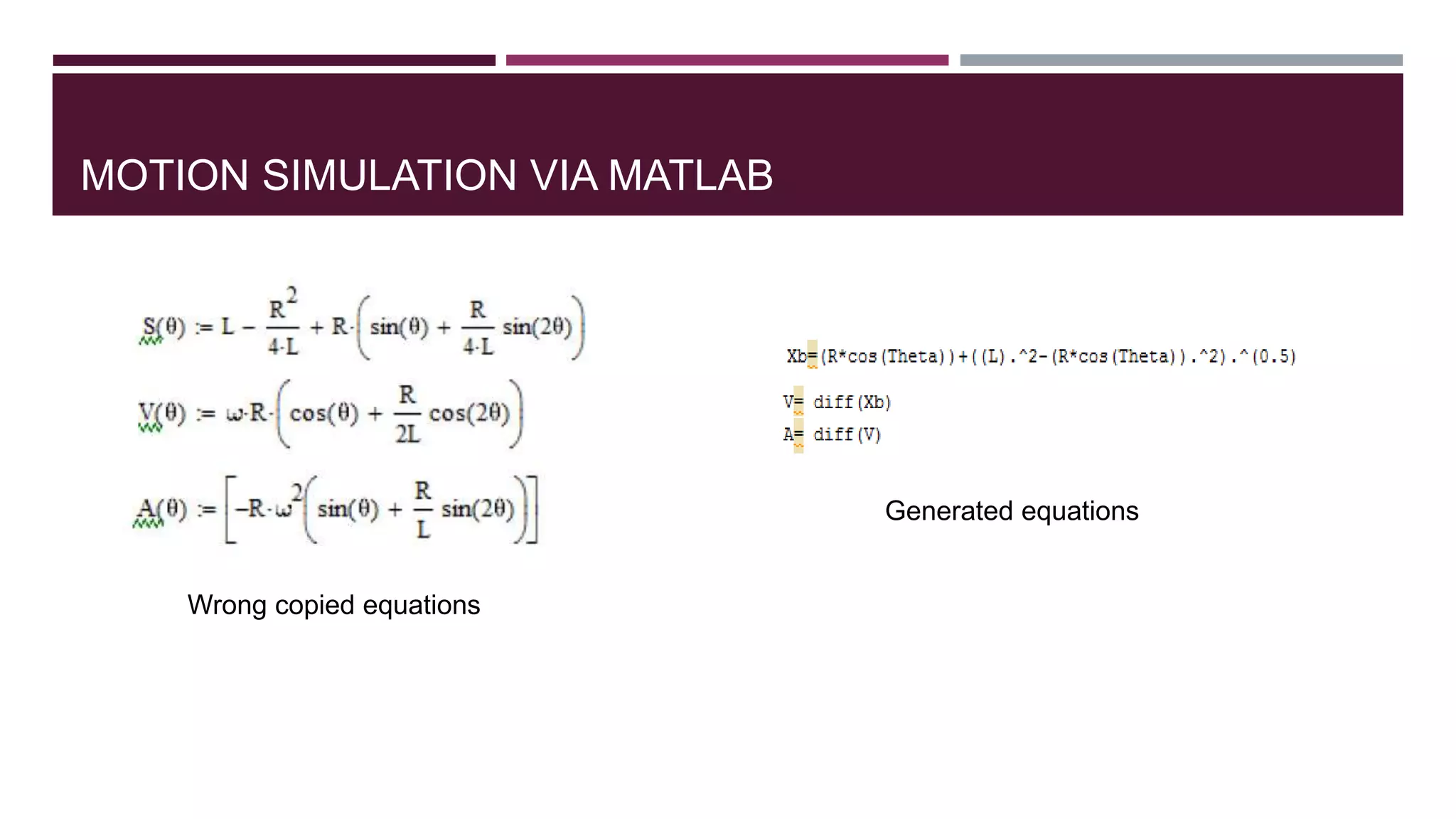
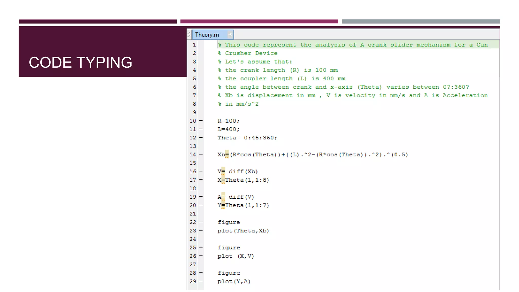
MATLAB Application: The Mechanism virtual prototype calculations
Displacement, velocity and acceleration equations’ is transfer to MATLAB
modeling.
Calculations of mechanisms’ degree of freedom, position, velocity and
acceleration of mechanism.
TEAM MEMBERS
AlaaFarag
Esraa Fathy
Joseph Maged
Ali Rawash
Ahmed Ibrahim
Ahmed Amin
Amr Elganainy
Mohamed Saadany
Nourhan Hany
Peter Adel