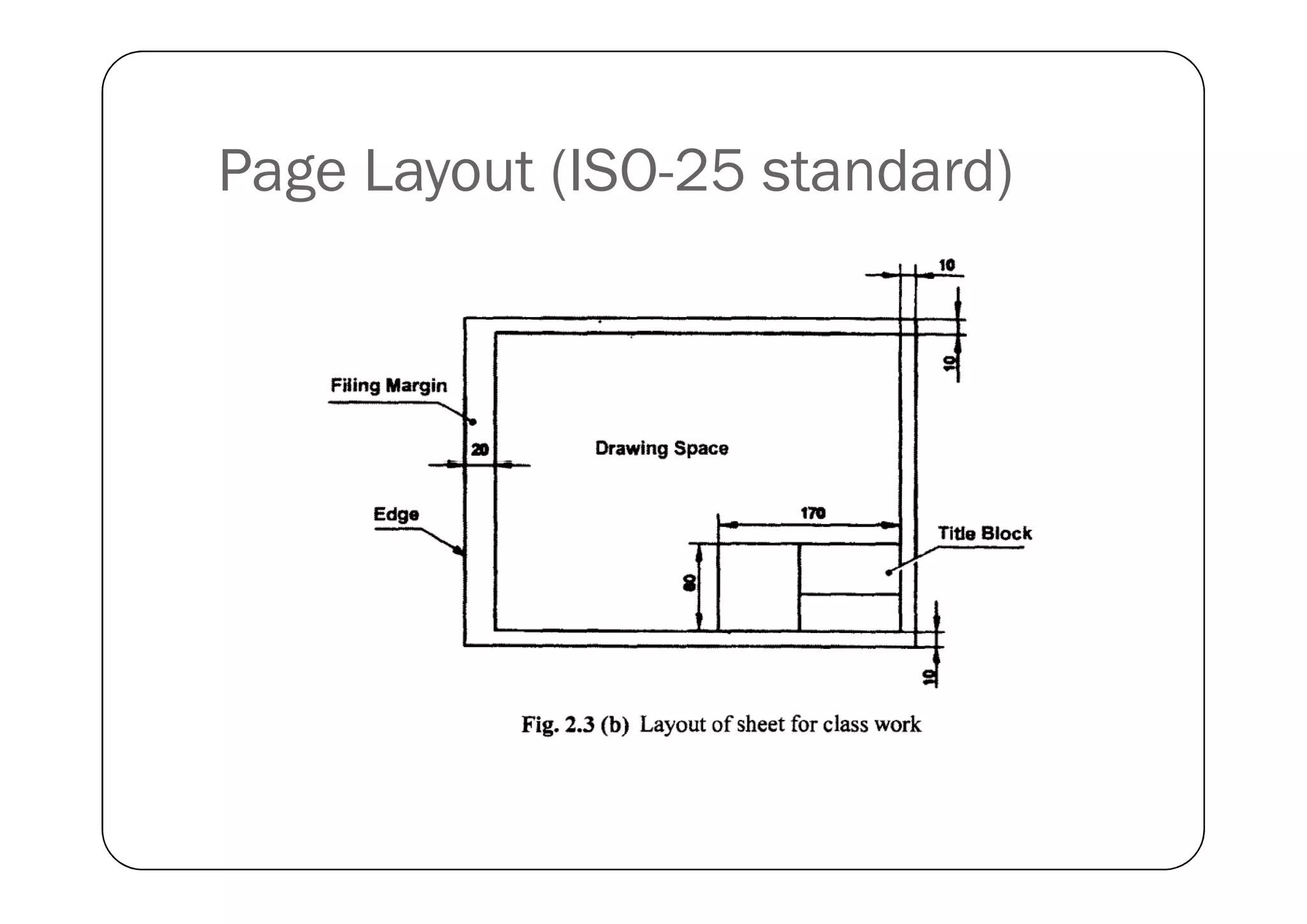
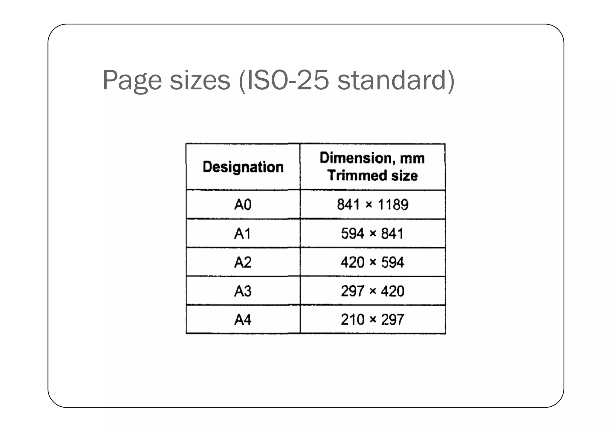
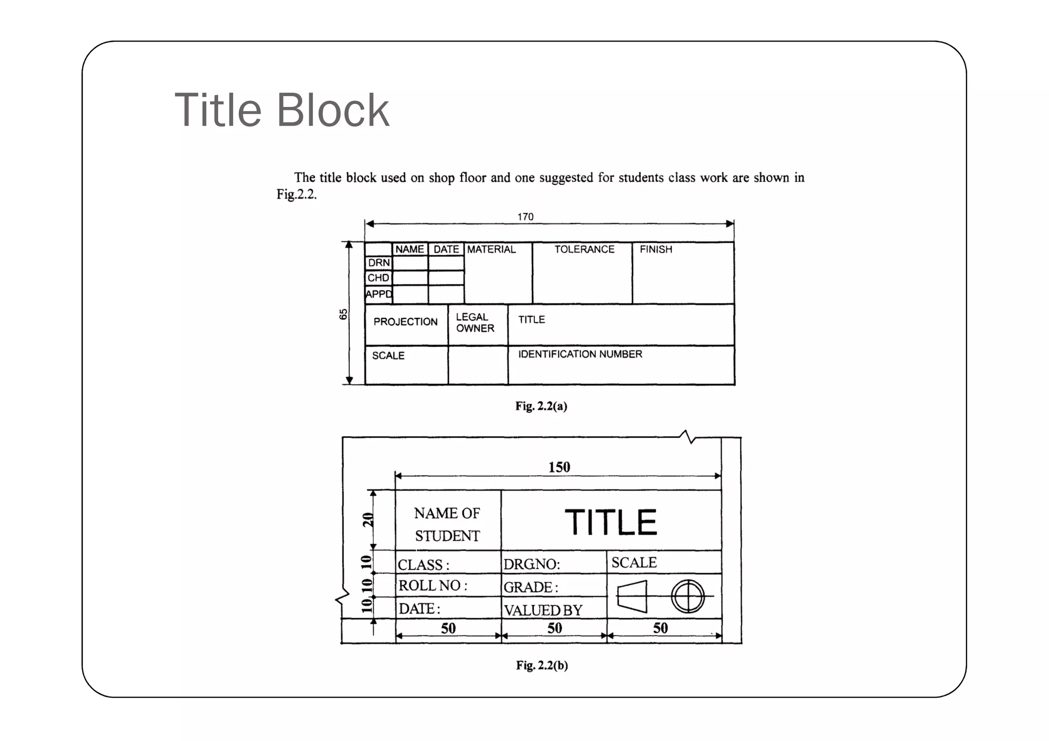
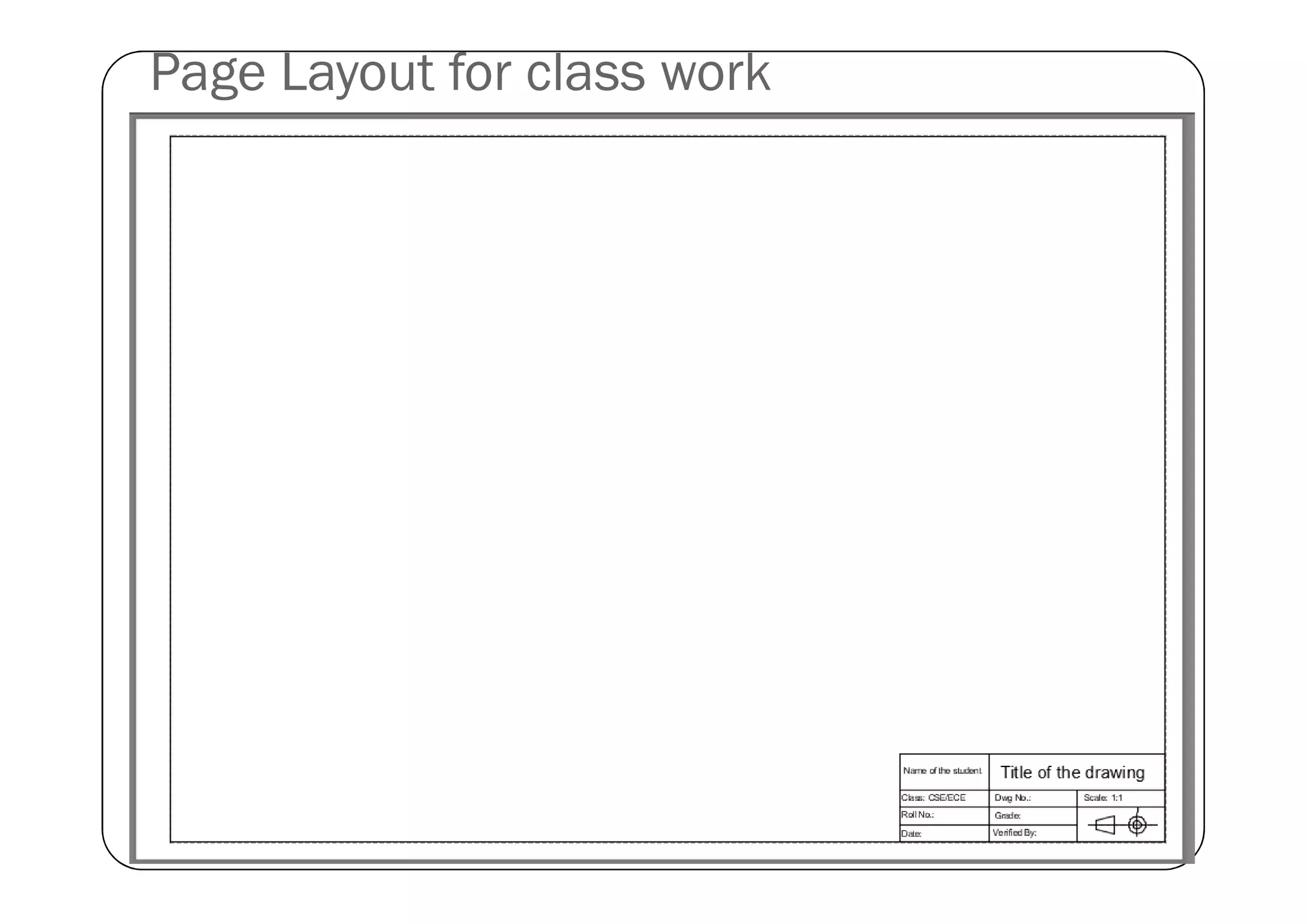
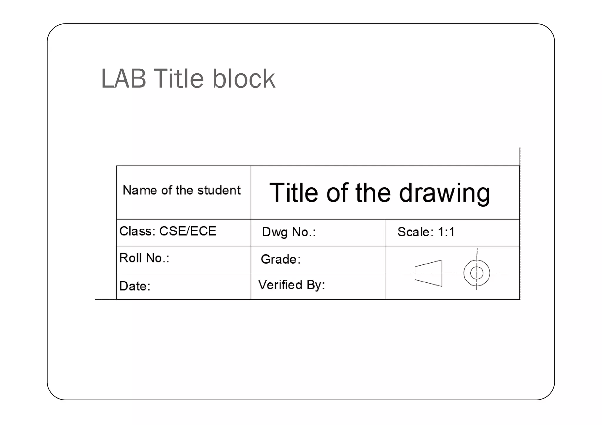
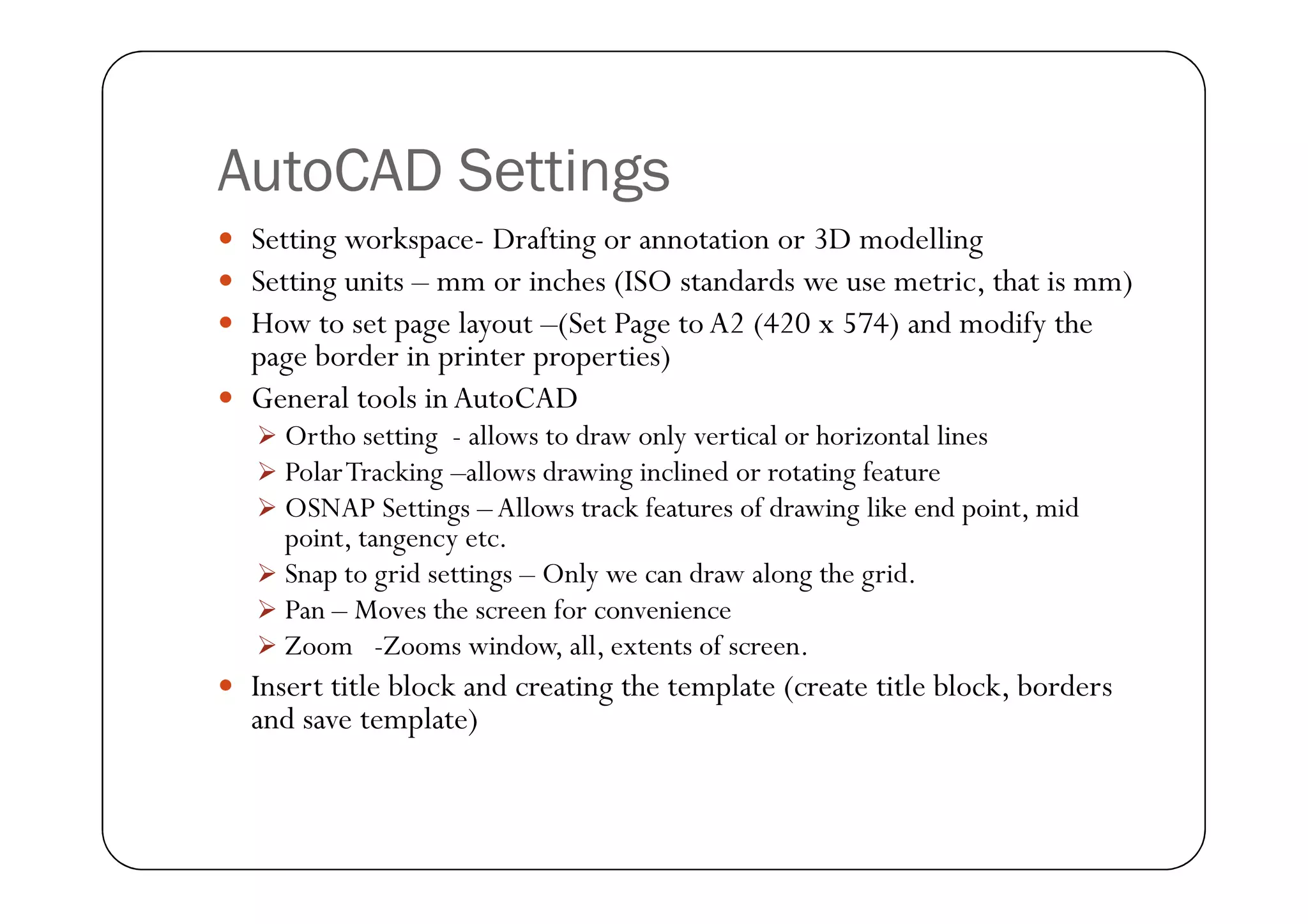
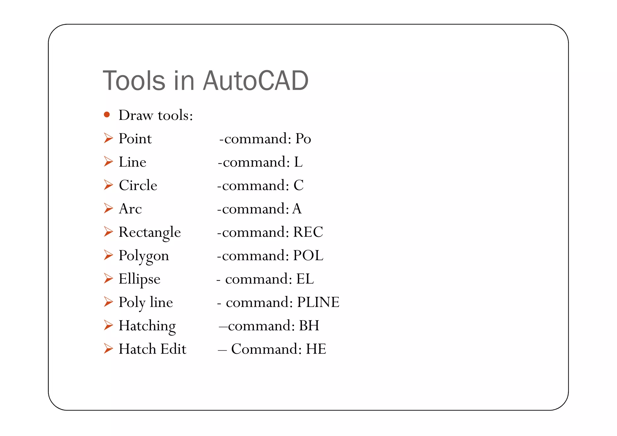
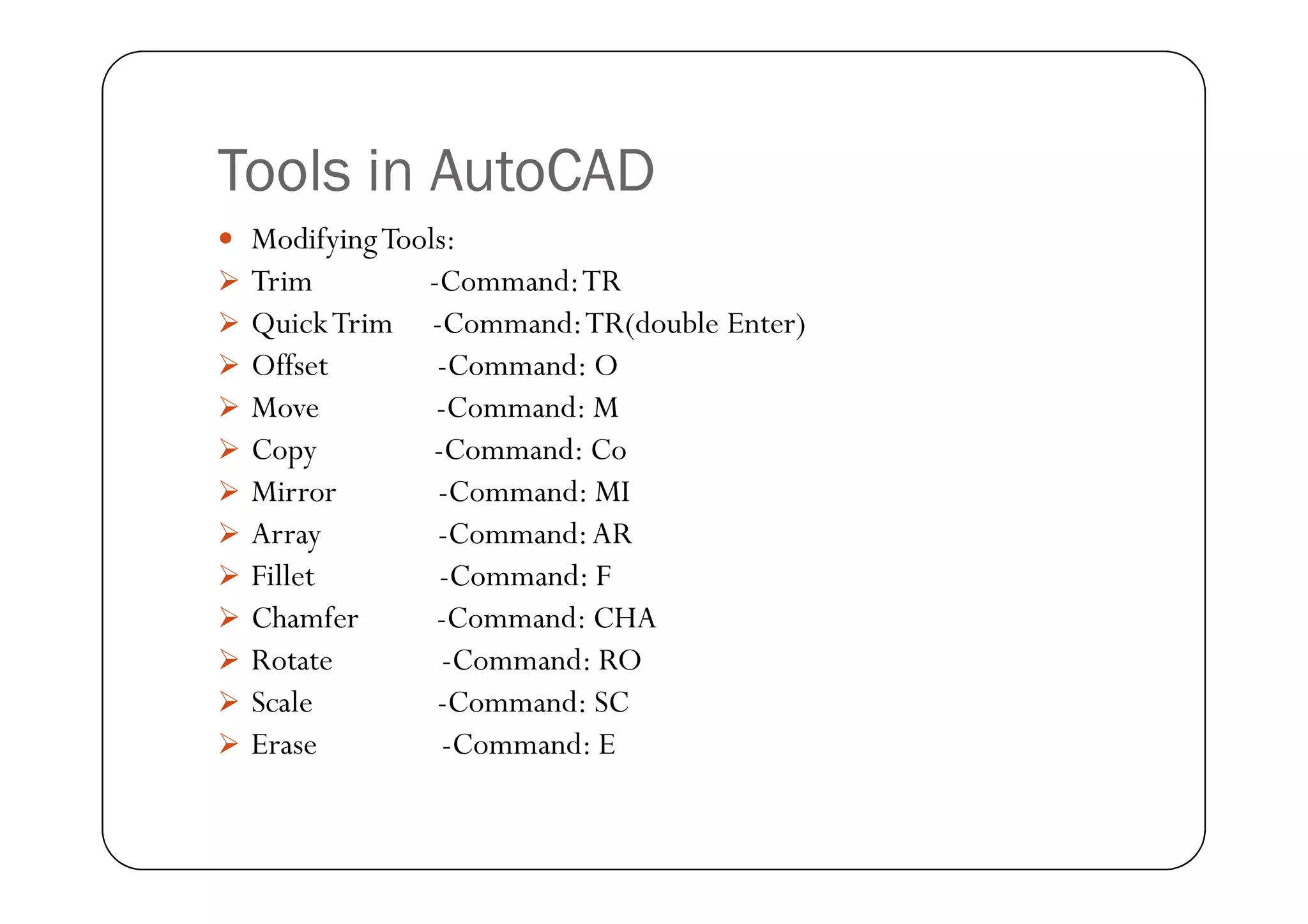
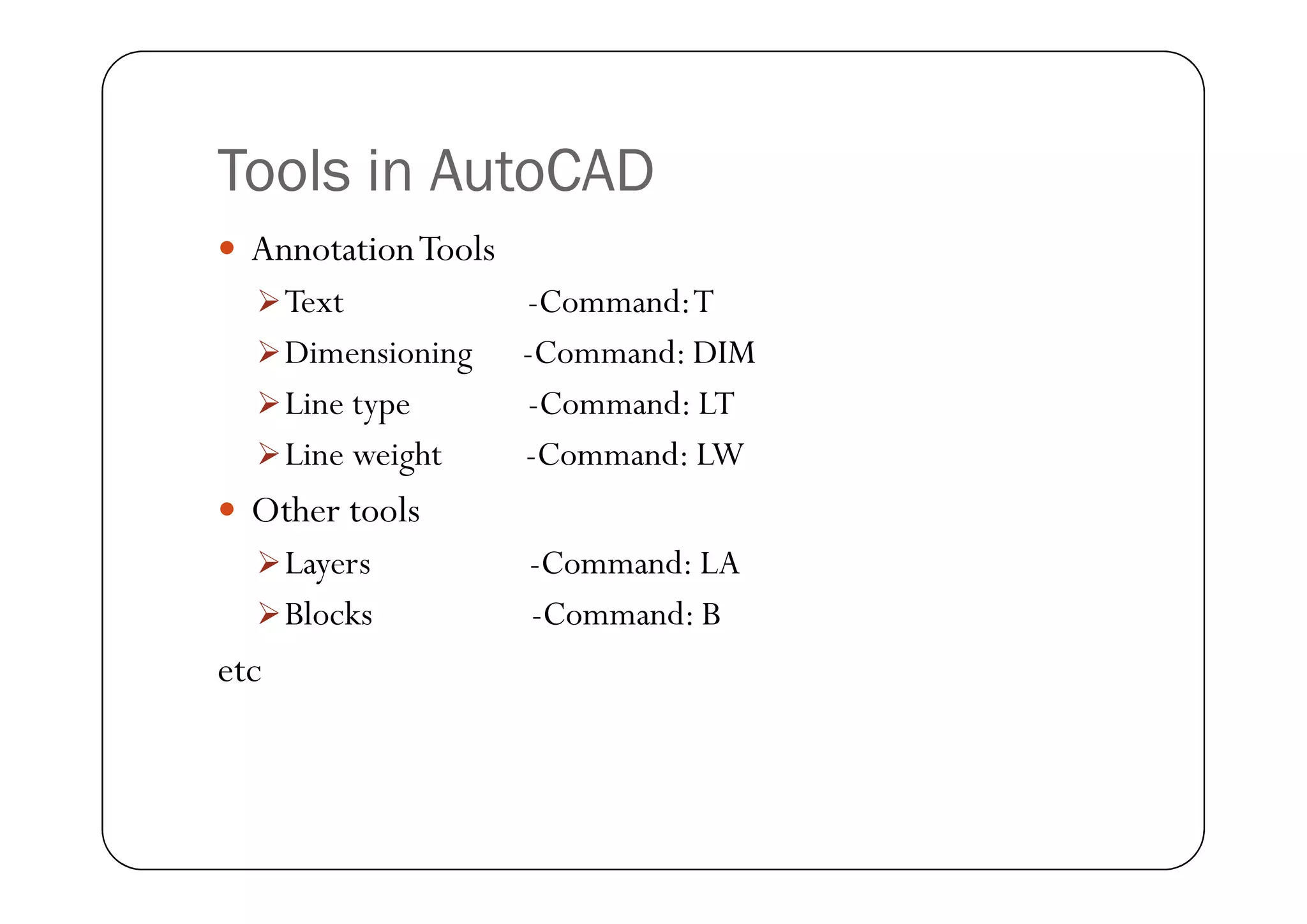
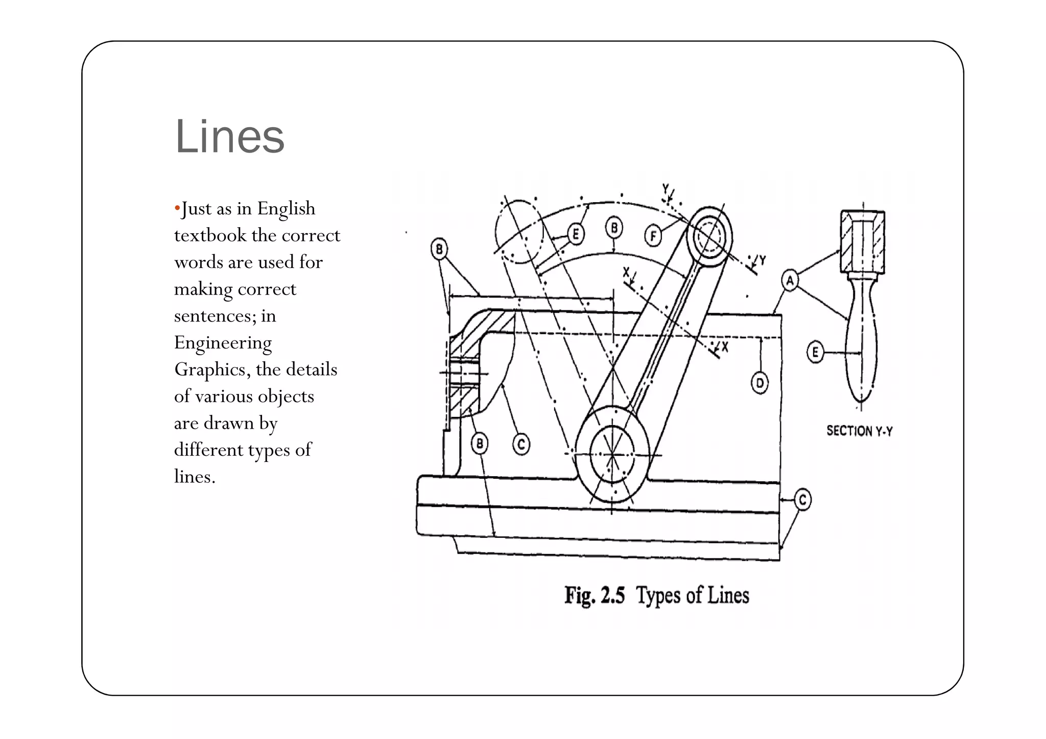
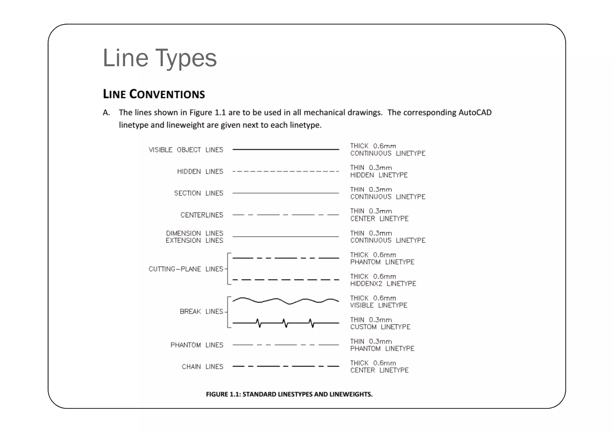
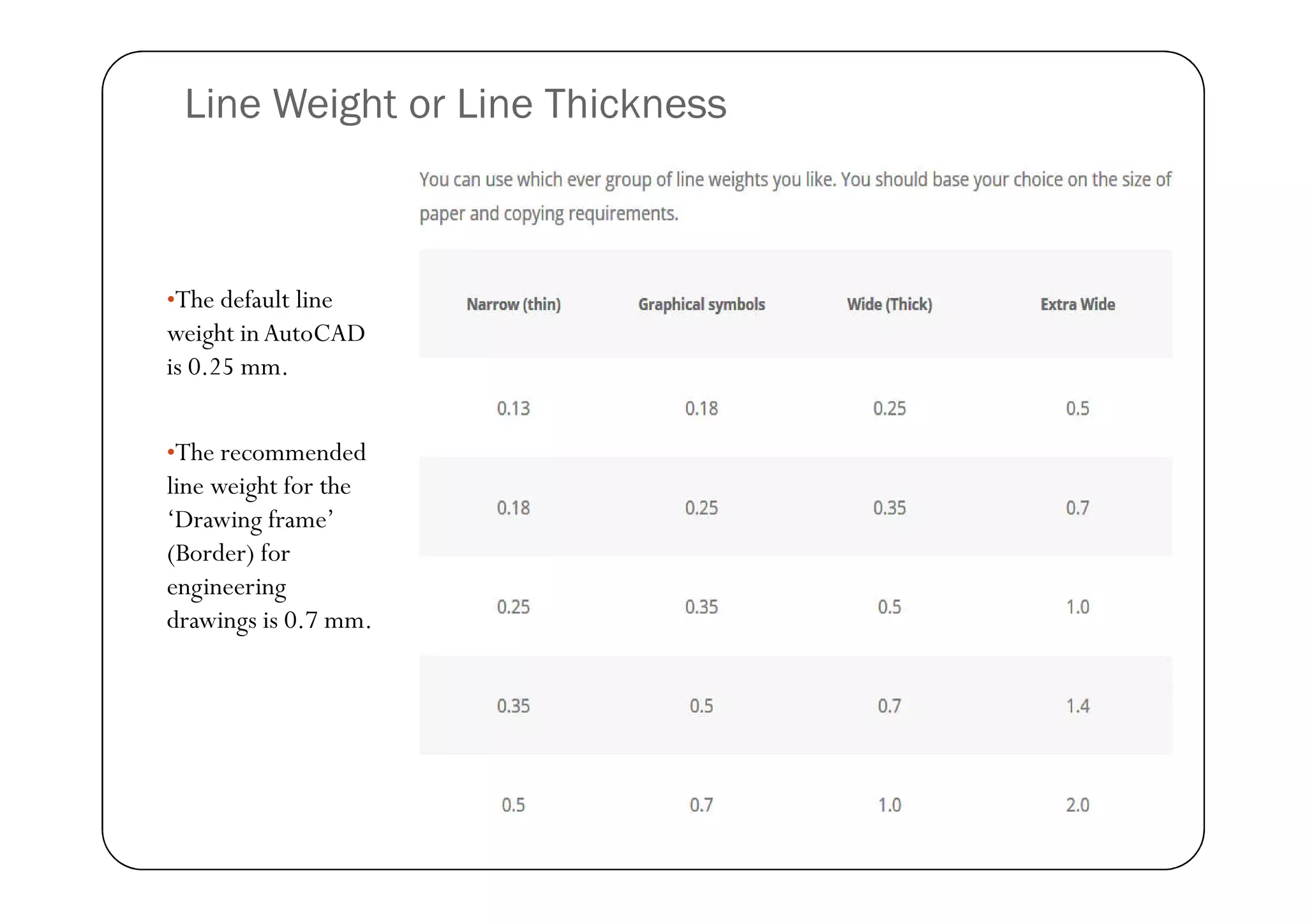
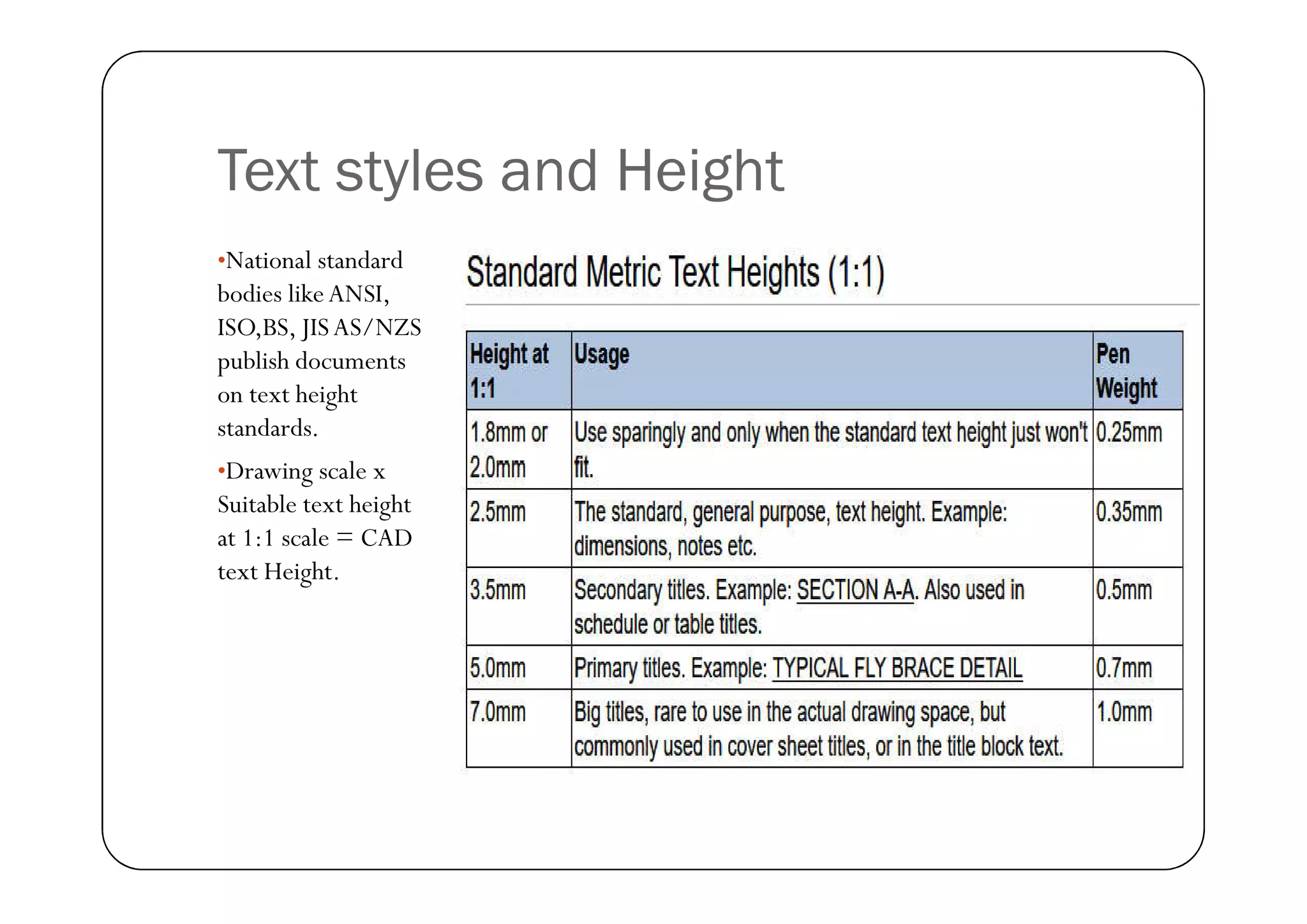
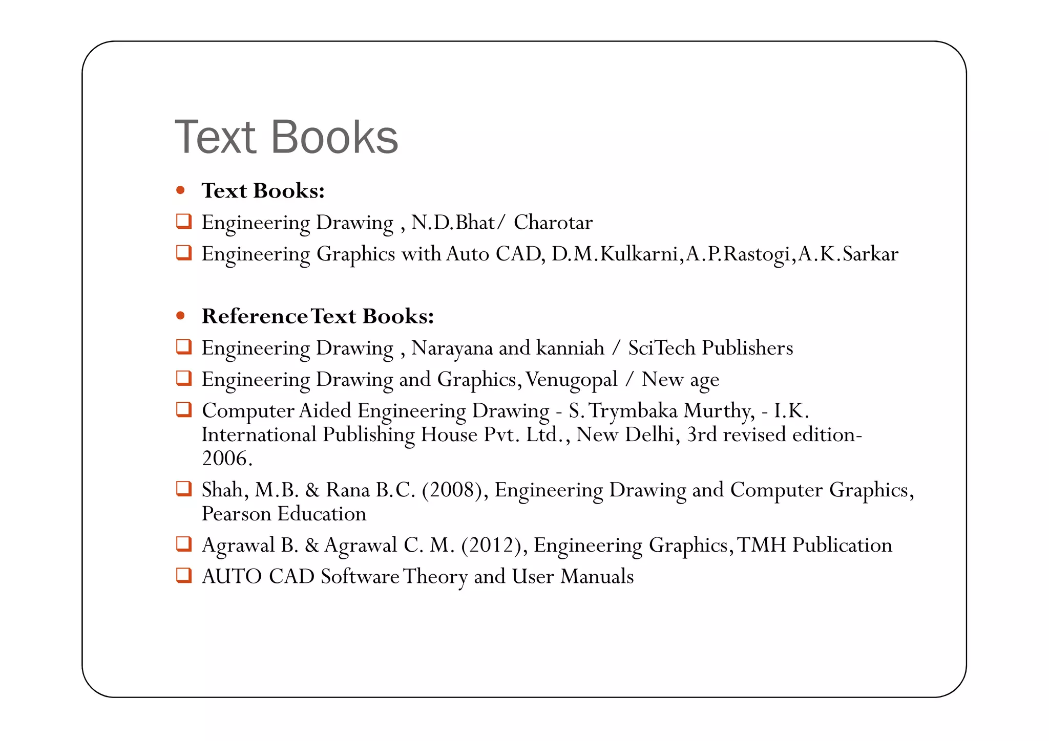
Computer Aided Engineering Drawing
Procedures and Standards in
Engineering Drawing
Engineering Drawing
Drawing Standards
 For the goal of unambiguous communication, engineering
drawings are expected to follow certain national and
international standards such as
 ISO Standards – International standards
 ASME standards-American Society of Mechanical Engineers
 BS standards- British standards
 JIS standards- Japanese standards association
 DIN- Deutsches Institute fur Normung (European Standards)
Page Layout (ISO-25 standard)
Page sizes (ISO-25 standard)
Title Block
Page Layout for class work
LAB Title block
AutoCAD Settings
 Setting workspace- Drafting or annotation or 3D modelling
 Setting units – mm or inches (ISO standards we use metric, that is mm)
 How to set page layout –(Set Page to A2 (420 x 574) and modify the
page border in printer properties)
 General tools in AutoCAD
 Ortho setting - allows to draw only vertical or horizontal lines
 PolarTracking –allows drawing inclined or rotating feature
 OSNAP Settings – Allows track features of drawing like end point, mid
point, tangency etc.
 Snap to grid settings – Only we can draw along the grid.
 Pan – Moves the screen for convenience
 Zoom -Zooms window, all, extents of screen.
 Insert title block and creating the template (create title block, borders
and save template)
Tools in AutoCAD
 Draw tools:
 Point -command: Po
 Line -command: L
 Circle -command: C
 Arc -command:A
Arc -command:A
 Rectangle -command: REC
 Polygon -command: POL
 Ellipse - command: EL
 Poly line - command: PLINE
 Hatching –command: BH
 Hatch Edit – Command: HE
Tools in AutoCAD
 ModifyingTools:
 Trim -Command:TR
 QuickTrim -Command:TR(double Enter)
 Offset -Command: O
 Move -Command: M
 Copy -Command: Co
 Copy -Command: Co
 Mirror -Command: MI
 Array -Command:AR
 Fillet -Command: F
 Chamfer -Command: CHA
 Rotate -Command: RO
 Scale -Command: SC
 Erase -Command: E
Tools in AutoCAD
 AnnotationTools
Text -Command:T
Dimensioning -Command: DIM
Line type -Command: LT
Line weight -Command: LW
 Other tools
Layers -Command: LA
Blocks -Command: B
etc
Lines
•Just as in English
textbook the correct
words are used for
making correct
sentences; in
Engineering
Graphics, the details
of various objects
are drawn by
different types of
lines.
Line Types
Line Weight or Line Thickness
•The default line
weight inAutoCAD
is 0.25 mm.
•The recommended
•The recommended
line weight for the
‘Drawing frame’
(Border) for
engineering
drawings is 0.7 mm.
Text styles and Height
•National standard
bodies likeANSI,
ISO,BS, JISAS/NZS
publish documents
on text height
standards.
•Drawing scale x
•Drawing scale x
Suitable text height
at 1:1 scale = CAD
text Height.
Examples of Text Heights
Dimensioning
•Drawing of component, in
addition to providing
complete shape description,
must also furnish
information regarding the
size description.
•The expression of the
features on a drawing, using
lines, symbols, figures and
notes is called dimensioning.
Principles of dimensioning
Placing the dimensions where
the shape is best known:
•Dimension should be placed
on the view where the shape is
best seen.
•As far as possible, dimensions
As far as possible, dimensions
should be expressed in one unit
only preferably in millimetres,
without showing the unit
symbol (mm) .
Principles of dimensioning
Placing the
dimensions outside
theView:
As far as possible
dimensions should
be placed outside
the view
the view
Principles of dimensioning
Marking the
extension lines:
No gap should be
left between the
feature and the start
of the extension line
Principles of dimensioning
Crossing of centre
lines should be done
by a long dash and
not a short dash
Methods of indicating dimensions-
Aligned method.
•Dimensions should
be placed parallel to
and above their
dimension lines and
preferably at the
middle, and clear of
the line.
the line.
Methods of indicating dimensions-
Aligned method: Angular dimensions
•Dimensions may be
written so that they
can be read from the
bottom or from the
right side of
the drawing.
Methods of indicating dimensions-
Uni directional Method
•Dimensions should
be indicated so that
they can be read from
the bottom of the
drawing only.
•Non-horizontal
dimension lines are
Non-horizontal
dimension lines are
interrupted,
preferably in the
middle for insertion
of the dimension
•Note: In any
method, horizontal
dimensioning should
not be interrupted.
Accessories student should carry with
them for learning this course
 Exercise Drawings
 Tutorial Notes
 Drawing Instruments like
 Scale
 Compass
 Compass
 Protractor
 Sets square etc
CO I exercises- AutoCAD Drafting
Complete with in 3 weeks (10 hrs)
Text Books
 Text Books:
 Engineering Drawing , N.D.Bhat/ Charotar
 Engineering Graphics with Auto CAD, D.M.Kulkarni,A.P.Rastogi,A.K.Sarkar
 ReferenceText Books:
 Engineering Drawing , Narayana and kanniah / SciTech Publishers
 Engineering Drawing and Graphics,Venugopal / New age
 ComputerAided Engineering Drawing - S.Trymbaka Murthy, - I.K.
International Publishing House Pvt. Ltd., New Delhi, 3rd revised edition-
2006.
 Shah, M.B. & Rana B.C. (2008), Engineering Drawing and Computer Graphics,
Pearson Education
 Agrawal B. & Agrawal C. M. (2012), Engineering Graphics,TMH Publication
 AUTO CAD SoftwareTheory and User Manuals

CAED lab standards pdf.pdf

  • 1.
  • 2.
    Procedures and Standardsin Engineering Drawing Engineering Drawing
  • 3.
    Drawing Standards  Forthe goal of unambiguous communication, engineering drawings are expected to follow certain national and international standards such as  ISO Standards – International standards  ASME standards-American Society of Mechanical Engineers  ASME standards-American Society of Mechanical Engineers  BS standards- British standards  JIS standards- Japanese standards association  DIN- Deutsches Institute fur Normung (European Standards)
  • 4.
  • 5.
  • 6.
  • 7.
    Page Layout forclass work
  • 8.
  • 9.
    AutoCAD Settings  Settingworkspace- Drafting or annotation or 3D modelling  Setting units – mm or inches (ISO standards we use metric, that is mm)  How to set page layout –(Set Page to A2 (420 x 574) and modify the page border in printer properties)  General tools in AutoCAD  Ortho setting - allows to draw only vertical or horizontal lines  PolarTracking –allows drawing inclined or rotating feature  PolarTracking –allows drawing inclined or rotating feature  OSNAP Settings – Allows track features of drawing like end point, mid point, tangency etc.  Snap to grid settings – Only we can draw along the grid.  Pan – Moves the screen for convenience  Zoom -Zooms window, all, extents of screen.  Insert title block and creating the template (create title block, borders and save template)
  • 10.
    Tools in AutoCAD Draw tools:  Point -command: Po  Line -command: L  Circle -command: C  Arc -command:A Arc -command:A  Rectangle -command: REC  Polygon -command: POL  Ellipse - command: EL  Poly line - command: PLINE  Hatching –command: BH  Hatch Edit – Command: HE
  • 11.
    Tools in AutoCAD ModifyingTools:  Trim -Command:TR  QuickTrim -Command:TR(double Enter)  Offset -Command: O  Move -Command: M  Copy -Command: Co  Copy -Command: Co  Mirror -Command: MI  Array -Command:AR  Fillet -Command: F  Chamfer -Command: CHA  Rotate -Command: RO  Scale -Command: SC  Erase -Command: E
  • 12.
    Tools in AutoCAD AnnotationTools Text -Command:T Dimensioning -Command: DIM Line type -Command: LT Line weight -Command: LW Line weight -Command: LW  Other tools Layers -Command: LA Blocks -Command: B etc
  • 13.
    Lines •Just as inEnglish textbook the correct words are used for making correct sentences; in Engineering Graphics, the details Graphics, the details of various objects are drawn by different types of lines.
  • 14.
  • 15.
    Line Weight orLine Thickness •The default line weight inAutoCAD is 0.25 mm. •The recommended •The recommended line weight for the ‘Drawing frame’ (Border) for engineering drawings is 0.7 mm.
  • 16.
    Text styles andHeight •National standard bodies likeANSI, ISO,BS, JISAS/NZS publish documents on text height standards. •Drawing scale x •Drawing scale x Suitable text height at 1:1 scale = CAD text Height.
  • 17.
  • 18.
    Dimensioning •Drawing of component,in addition to providing complete shape description, must also furnish information regarding the size description. •The expression of the features on a drawing, using lines, symbols, figures and notes is called dimensioning.
  • 19.
    Principles of dimensioning Placingthe dimensions where the shape is best known: •Dimension should be placed on the view where the shape is best seen. •As far as possible, dimensions As far as possible, dimensions should be expressed in one unit only preferably in millimetres, without showing the unit symbol (mm) .
  • 20.
    Principles of dimensioning Placingthe dimensions outside theView: As far as possible dimensions should be placed outside the view the view
  • 21.
    Principles of dimensioning Markingthe extension lines: No gap should be left between the feature and the start of the extension line
  • 22.
    Principles of dimensioning Crossingof centre lines should be done by a long dash and not a short dash
  • 23.
    Methods of indicatingdimensions- Aligned method. •Dimensions should be placed parallel to and above their dimension lines and preferably at the middle, and clear of the line. the line.
  • 24.
    Methods of indicatingdimensions- Aligned method: Angular dimensions •Dimensions may be written so that they can be read from the bottom or from the right side of the drawing.
  • 25.
    Methods of indicatingdimensions- Uni directional Method •Dimensions should be indicated so that they can be read from the bottom of the drawing only. •Non-horizontal dimension lines are Non-horizontal dimension lines are interrupted, preferably in the middle for insertion of the dimension •Note: In any method, horizontal dimensioning should not be interrupted.
  • 26.
    Accessories student shouldcarry with them for learning this course  Exercise Drawings  Tutorial Notes  Drawing Instruments like  Scale  Compass  Compass  Protractor  Sets square etc
  • 27.
    CO I exercises-AutoCAD Drafting Complete with in 3 weeks (10 hrs)
  • 28.
    Text Books  TextBooks:  Engineering Drawing , N.D.Bhat/ Charotar  Engineering Graphics with Auto CAD, D.M.Kulkarni,A.P.Rastogi,A.K.Sarkar  ReferenceText Books:  Engineering Drawing , Narayana and kanniah / SciTech Publishers  Engineering Drawing and Graphics,Venugopal / New age  Engineering Drawing and Graphics,Venugopal / New age  ComputerAided Engineering Drawing - S.Trymbaka Murthy, - I.K. International Publishing House Pvt. Ltd., New Delhi, 3rd revised edition- 2006.  Shah, M.B. & Rana B.C. (2008), Engineering Drawing and Computer Graphics, Pearson Education  Agrawal B. & Agrawal C. M. (2012), Engineering Graphics,TMH Publication  AUTO CAD SoftwareTheory and User Manuals