Downloaded 16 times
![Design And Optimization Of Front Underrun Protection Device
www.iosrjournals.org 25 | Page
Fig. 15 Front Underrun Protection Device after optimized mass is 21.49kgs.
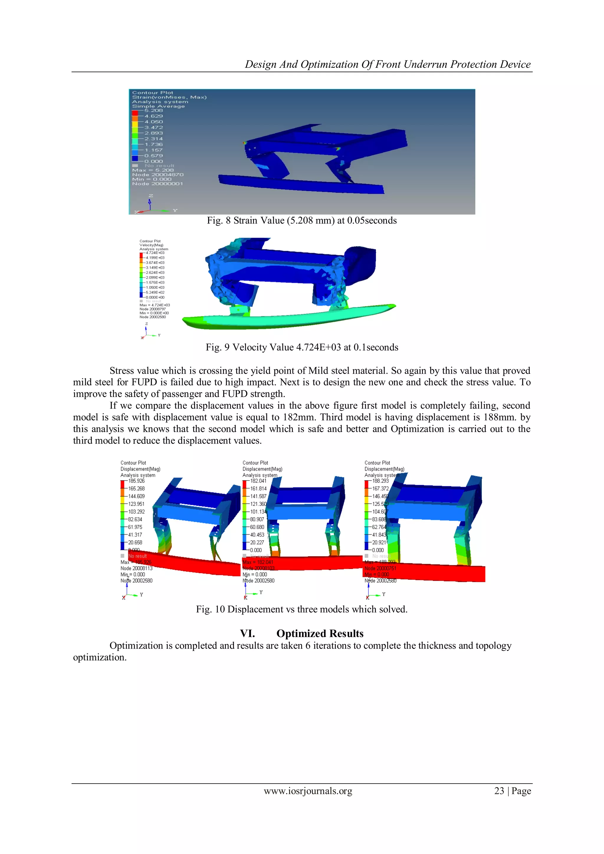
Weight reduction achieved by optimization result is 6%, compared to base third model. Finally we
conclude that the optimized model results are less than the third design model. By this we can say that
optimized front under run protection device is selected. Front under run protection is achieved less weight, less
displacement and less stress so that for the passenger who are sitting in the car having high safety by placing this
optimized model.
VII. Conclusions
Head on collision contribute significant amount of serious accidents which causes driver fatalities. The
car safety performances can work effectively by providing FUPD to the heavy trucks. The trucks with UPD can
reduce the car driver fatalities by 40 % In India, for Front Under-run Protection Device, IS 14812:2005
regulation is required in for the trucks to meet the safety requirement to protect under running of the passenger
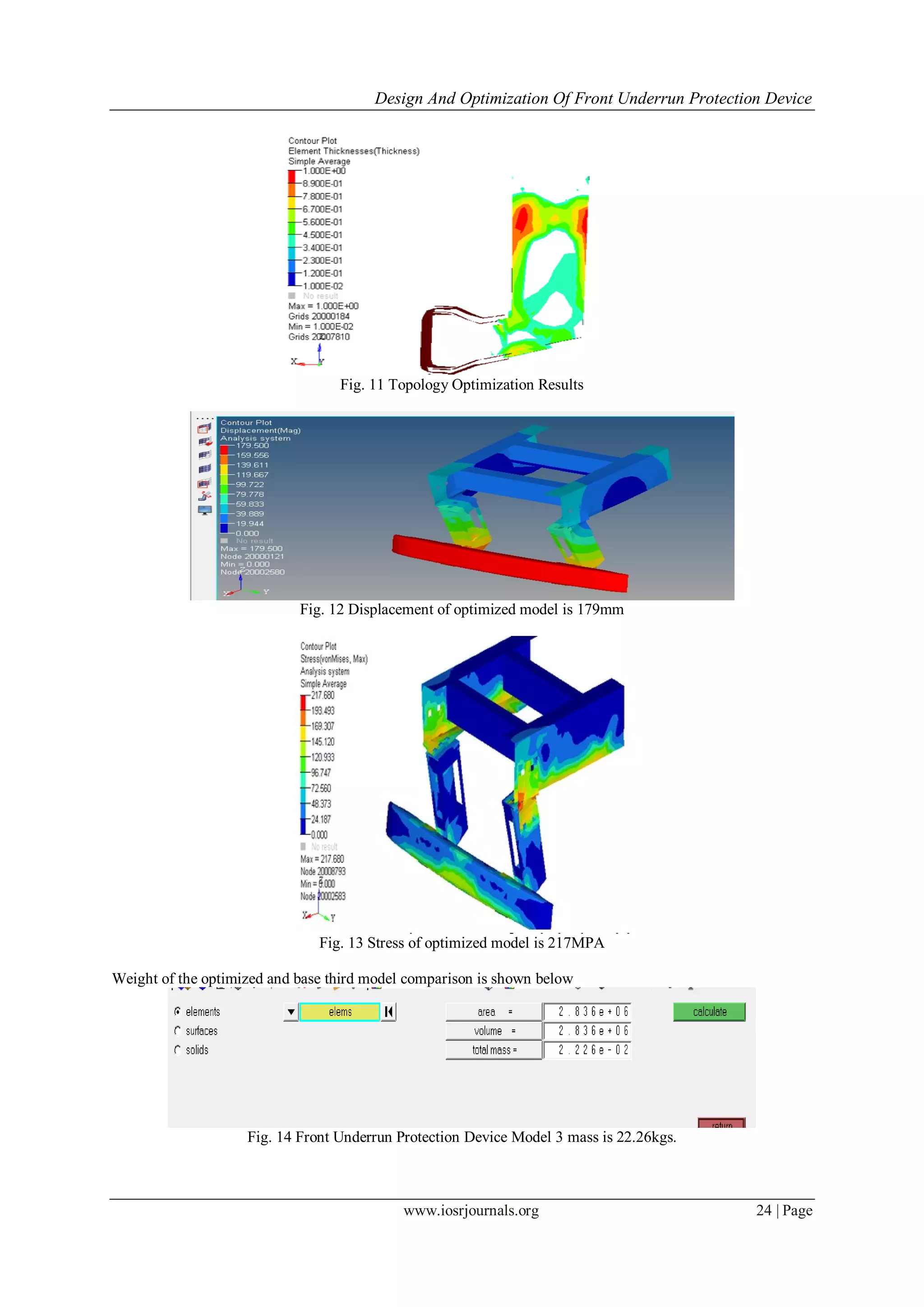
car. In above said design, the maximum displacement of FUPD bar is limited to 179mm hence it meet the
requirements as per IS 14812:2005. But this needs to be confirmed with physical testing in future. The virtual
simulation is tool which can be used to avoid or reduce the physical testing of mechanical systems and
components. Overall effect of this is cost saving and same is done with FUPD analysis.
As per above results optimized model is safe, more strength and low weight mode suits the best
suggested design. Weight reduction achieved by optimization result is 6%, compared to base third Model and
displacement is about 5% and Stress is 6%.Finally we conclude that the optimized model results are less than
the third design model. By this we can say that optimized front under run protection device is selected. Front
under run protection is achieved less weight, less displacement and less stress so that for the passenger who is
sitting in the car having high safety by placing this optimized model. We can suggest to automobile industries to
keep this type of Front Underrun Protection Device to truck, busses etc which saves the life of passenger with
less injury.
Acknowledgements
First and foremost,I would like to express my deep sense of gratitude and indebtedness to my supervisor
Dr.T.Ramamohan Rao for his encouragement ,suggestions and support from an early stage of this research and
providing me the extraordinary experiences throughout the work Above all, his priceless and meticulous
supervision at each and every phase of work inspired me in innumerable ways.
References
[1] Jim Anderson CIC, Cranfield Impact Centre, UK, Johann Gwehenberger GDV, Institute for
Vehicle Safety, Munich, DE, JenöBende GDV, Institute for Vehicle Safety, Munich, DE FlorisLeneman TNO Automotive, NL
“Truck/Trailer Compatibility with Cars and Related Topics from VC-COMPAT”
[2] Matej Glavac, Univ.Dipl.-Ing., Prof. Dr. Zoran Ren University of Maribor, Faculty of Mechanical Engineering “Computational
Approval for Rear Under Run Protection Device with MSC. Nastran” 2001126
[3] “Safety inspection of rear underrun protection device in Slovenia (No. 58.01)”, Uradni list RepublikeSlovenije, No. 3, 20.1.1995, p.
182-183
[4] Liu Hong-Fei and Peng Tao Xu Hong-Guo, Tan Li-dong and Su Li-li College of Transportation University of Jilin, Changchun,
Jilin province, China “Research on the Intelligent Rear Under-run Protection
System for Trucks” Proceedings of the 8th World Congress on Intelligent Control and Automation July 6-9 2010, Jinan, China
[5] Kaustubh Joshi, T.A. Jadhav, Ashok Joshi “Finite Element Analysis of Rear Under-Run Protection Device (RUPD) for Impact
Loading” International Journal of Engineering Research and Development ISSN: 2278- 067X, Volume 1, Issue 7 (June 2012),
PP.19-26 www.ijerd.com
[6] Zou R., Rechnitzer G., Grzebieta R. “Simulation of Truck Rear Underrun Barrier Impact", 17th International Technical
Conference on the Enhanced Safety of Vehicles, Amsterdam, June 4-7, 2001.
[7] Muxi LEI,Zhengbao LEI, Shubin WEI,YonghanLI “Geometry optimization design for crank-slider-CST type low rear protection
device of truck”978-1-61284-459-6/11/©2011 IEEE
[8] Nitin S Gokhale "Practical Finite Element Analysis" Finite to infinite,Pune.
[9]. Bjornstig J, Bjornstig Ulf, Eriksson A, “Passenger car collision fatalities - With special emphasis on collision with heavy vehicles”,
Accident Analysis and Prevention 2008, P 158-166.](https://image.slidesharecdn.com/c0821925-150115233725-conversion-gate02/75/Design-and-Optimization-of-Front-Underrun-Protection-Device-7-2048.jpg)

This document details the design and optimization of a front underrun protection device (FUPD) aimed at enhancing car occupant safety during collisions with heavy vehicles, particularly trucks. It discusses the use of computational simulations and finite element analysis to evaluate and improve the performance of the FUPD, complying with Indian standards IS 14812-2005. The study concludes that the optimized FUPD design achieves reduced weight, lower displacement, and less stress, significantly improving passenger safety in collisions.