(ANVI) Koregaon Park Call Girls Just Call 7001035870 [ Cash on Delivery ] Pun...
C insights-linville line-june-091
1. newtrends,newtechniquesandcurrentindustryissues
InSights
STRUCTURE magazine June 200930
Seismic Design of Glulam Arches
By Jeffrey Linville, P.E. and Philip Line, P.E.
S
tructural glued laminated timber (glulam) arches continue to be popular
for use in large open structures such as churches and gymnasiums for
many reasons which include their structural performance, inherent fire
resistance, and aesthetic appeal.This structural system has been used successfully
in North America since its debut in the 1930s. Until recently, there has only
been limited guidance for design of arches to resist seismic loads, leaving the
choice of seismic design coefficients to the discretion of the design engineer and
local building official.
Seismic Coefficients for
Glulam Arches
Seismic design coefficients for glulam
arches shown in Table 1 are based
on those presented in a paper titled
“Special Requirements for Seismic
Design of Structural Glued Laminated
Timber (Glulam) Arch Members and
Their Connections in Three-hinge
Arch Systems” in Part 3 of the 2009
NEHRP (National Earthquake Hazard
Reduction Program) Recommended
Seismic Provisions for New Buildings and
Other Structures (FEMA P750) and are
intended for use with design provisions
of ASCE 7-05 Minimum Design
Loads for Buildings and Other Structures
(ASCE7-05).
Seismic coefficients and detailing re-
quirements proposed in the paper
reflect a new approach and are included
in Part 3 of the NEHRP Provisions to
stimulate broad review, trial use, and/
or additional study before integration
into a national standard or model
building code.
base shear to ASCE 7-05 base shear (with
mapped short period spectral response
acceleration, Ss, equal to 1.5) was made. It
was found that a value of R = 2.5 coupled
with use of ASCE 7-05 provisions gives
approximately the same base shear as
derived from the 1997 UBC.
Detailing Requirements for
Special Glulam Arches
For timber structures, ductility is ob-
tained through connection yield mech-
anisms, such as fastener bending and
localized wood crushing at connections
or points of bearing. Failure of timber
members themselves is generally charac-
terized as brittle. For a special glulam arch
system, detailing requirements provide
additional assurance that the timber
components of an arch system will have
greater strength relative to connections.
This is done by sizing the member to
resist over-strength load combinations of
ASCE 7 or ensuring that members have
capacity to develop the nominal strength
of the connections. To promote yielding
mechanisms, fasteners are designed to
resist seismic loads without considering
over-strength load combinations.
Seismic Load Distribution
A Tudor arch resists lateral and vertical
loads primarily through bending. As
such, distribution of loads throughout the
arch affects the deflected shape and stress
distribution in the arch. It is, therefore,
not recommended to concentrate the
seismic mass of the structure at a single
location for design of the arch member;
the load (mass) should be distributed as it
occurs along the arch length.
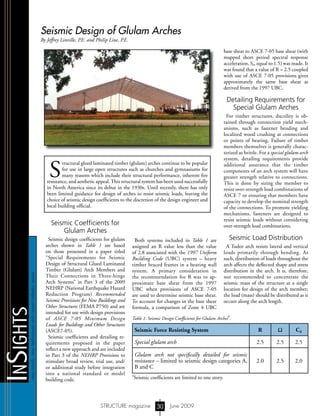
Seismic Force Resisting System R Ω Cd
Special glulam arch 2.5 2.5 2.5
Glulam arch not specifically detailed for seismic
resistance – limited to seismic design categories A,
B and C
2.0 2.5 2.0
Table 1: Seismic Design Coefficients for Glulam Arches
a
.
a
Seismic coefficients are limited to one story.
Both systems included in Table 1 are
assigned an R value less than the value
of 2.8 associated with the 1997 Uniform
Building Code (UBC) system – heavy
timber braced frames in a bearing wall
system. A primary consideration in
the recommendation for R was to ap-
proximate base shear from the 1997
UBC when provisions of ASCE 7-05
are used to determine seismic base shear.
To account for changes in the base shear
formula, a comparison of Zone 4 UBC
S T R U C T U R E
®
m
agazine
Copyright
2. STRUCTURE magazine June 2009
ADVERTISEMENT-ForAdvertiserInformation,visitwww.STRUCTUREmag.org
31
Steps for Seismic Analysis
Assuming that the arch has already been de-
signed to meet design criteria for loads other
than seismic, application of new detailing
concepts for seismic design of the special arch
includes the following steps:
1) Apply seismic load combinations without
over-strength factors and verify that the
connection design capacity is adequate.
At the base, also verify Mode III or Mode
IV yielding for dowels or rivet yielding
for timber rivets.
2) Determine the ratio of demand to
capacity of the connection (D/C) where
D is the demand and C is the nominal
capacity of the connection (divided by
1.35 for allowable stress design (ASD)).
3) Verify that combined member stresses
do not exceed 1.0 and that member
failure modes at connections such as
row and group tear-out and shear have
capacity in excess of:
a) Forces based on nominal connection
capacities. Increasing arch loads by
multiplying by 1/(D/C) can be used
to establish design member forces
limited by nominal connection
capacities; or,
b) Forces resulting from seismic load
combinations with over-strength
factors (ASCE 7-05, Section 12.4.3.2).
4) Apply load and resistance factor design
(LRFD) seismic load combinations and
check drift against applicable limits.
(Seismic drift limits are associated
with LRFD load levels, so LRFD load
combinations must be used, even for
ASD design).
Conclusion
Glulam arches have been used successfully
for over 70 years in North America; however,
guidance for seismic design has been limited.
New techniques for design and detailing of a
special glulam arch system are presented in a
paper titled “Special Requirements for Seismic
Design of Structural Glued Laminated
Timber (Glulam) Arch Members and Their
Connections in Three-hinge Arch Systems”
in Part 3 of the 2009 NEHRP Recommended
Provisions. Special detailing provisions ensure
that arch members have sufficient wood
capacity to promote yielding mechanisms
in connections. The response modification
factor, R, produces approximately the same
base shear used in prior codes recognizing that
base shear formulas have changed between the
1997 UBC and ASCE 7-05.▪
Philip Line, P.E. is Senior Manager, Engineering Research for the American Wood Council of
the American Forest Paper Association (AFPA). He works extensively with wood industry
technical committees on the development of wood design standards including the National Design
Specification®
(NDS®
) for Wood Construction. He also serves on the BSSC Provisions Update
Committee, ASCE 7 Seismic Subcommittee and ASTM D07 Committee on Wood.
Jeffrey Linville, P.E. is the Director of Technical Services for the American Institute of Timber
Construction, the national trade association representing the structural glued laminated
timber industry. He serves on several industry technical committees including the ASTM D07
Committtee on Wood, the American Wood Council technical committees, and the AASHTO
wood subcommittee.
VERSATILE GEOTECHNICAL CONTRACTORS
Cutter Soil Mixing for Ground Treatment Earth Retention
At Nicholson Construction Company, we specialize in versatile geotechnical
solutions for deep foundations, earth retention, ground treatment and ground
improvement. Cutter Soil Mixing is an innovative example of our advanced
construction techniques. Nicholson maintains fully staffed regional offices
where local project requirements are addressed with unparalleled resources
of our global network. When your project requires proven performance and
technical innovation, build on us.
412.221.4500
nicholsonconstruction.com
MICROPILES n ANCHORS n GROUTING n AUGERCAST PILES
SOIL NAIL WALLS n SOIL MIXING n DIAPHRAGM WALLS n VIBRO TECHNOLOGIES
S T R U C T U R E
®
m
agazine
Copyright