Sales & Marketing Alignment: How to Synergize for Success
Wcee2012 4617
1. From Theory to Practice: Design, Analysis and
Construction of Dissipative Timber Rocking
Post-Tensioning Wall System for
Carterton Events Centre, New Zealand
A. Palermo, F. Sarti, A. Baird & D. Bonardi
University of Canterbury, Christchurch, New Zealand
D. Dekker, S. Chung
Opus International Consultants, New Zealand
SUMMARY:
This paper describes the structural design of the Carterton Events Centre, located approximately 100km north of
Wellington, New Zealand. Primary focus is given to the structure’s seismic resistant system which consists of
dissipative timber rocking post-tensioning walls. The auditorium features eleven of these walls, each 6.7m tall,
2.4m long and 180mm thick with a central slot for post-tensioned bars. Energy dissipation is provided by
embedded mild steel rods.
Detailed description of design philosophy, connection detailing and construction phases are herein deeply
explained. As a final step of this collaborative design process, the University of Canterbury carried out non-
linear dynamic response history analysis as an additional check of the structural design. Simplified lumped
plasticity models, already developed for concrete structures have been adopted to model the rocking walls.
Results were consistent with the design procedure. Carterton Event Centre strengthened the belief of the authors
in the potential of the Pres-Lam technology.
Keywords: LVL, hybrid-rocking system, design, construction, non-linear modelling, response-history analysis
1. INTRODUCTION
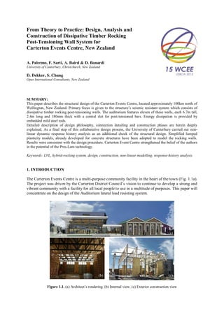
The Carterton Events Centre is a multi-purpose community facility in the heart of the town (Fig. 1.1a).
The project was driven by the Carterton District Council’s vision to continue to develop a strong and
vibrant community with a facility for all local people to use in a multitude of purposes. This paper will
concentrate on the design of the Auditorium lateral load resisting system.
Figure 1.1. (a) Architect’s rendering. (b) Internal view. (c) Exterior construction view
(a)
(b) (c)
2. Once the design process showed the Pres-Lam LVL (Palermo et al. 2006) wall option was the best
solution for the Auditorium structure, the walls were designed using displacement based design
principles (Priestley et al. 1999, Nakaki et al. 1999). The auditorium features 11 Pres-Lam LVL shear
walls, 6.7 metres tall, 2.4 metres long and 180millimetres thick with a central slot for the post-
tensioned bars. Two D40 post-tensioning bars for each wall provide self-centering capacity to the
system minimizing post-earthquake residual drifts (Pampanin et al. 2003) (Fig. 1.1b-c).
2. PRES-LAM SYSTEMS
Innovative post-tensioned seismic damage-resistant solutions were first investigated in the 1990s as a
main outcome of the PREcast Seismic Structural Systems (PRESSS) program, coordinated by the
University of California, San Diego (Nakaki et al., 1999, Priestley, 1991, Priestley, 1996).
Among different technologies developed in the PRESSS program, the hybrid system, proved to be a
promising and efficient solution and capable to concentrate damage at the interface between either
beam-to-column or wall-to-foundation interface.
Option 1 Option 2 Option 3
(a) (b) (c)
Figure 2.1. Wall dissipation options: (a) internal bars, (b) internal replaceable bars, (c) external fused bars
In recent years, the PRESSS-technology has been extended to timber (engineered wood) structural
systems (Palermo et al., 2006a, Smith, 2006, Iqbal et al., 2007). This extension expanded to new
structural systems, referred to as Pres-Lam (Pre-stressed Laminated) systems, which consist of large
timber structural frames or walls made of engineered wood products, such as LVL, glulam, Cross-Lam
(CLT), and capable of resisting seismic actions with minimal damage to the timber element.
Both internal glued in bars, as shown in Fig. 2.1a, and external devices (Fig. 2.1b-c) have been
developed as a way of adding energy dissipation to the Pres-Lam system. Design methods are aimed at
maximising energy dissipation potential whilst retaining the ability to re-centre the system during
lateral loading.
Results of quasi-static and pseudo-dynamic tests on beam-column joints and wall subassemblies
confirmed the enhanced performance of hybrid timber technology. No damage occurred in the
structural element, and high levels of ductility were reached without significant stiffness degradation
(Palermo et al., 2006a, Palermo et al., 2006b, Iqbal et al., 2007).
3. CONCEPTUAL DESIGN OF AUDITORIUM
The auditorium forms part of the Carterton Events Centre complex. The space provided is multi use
and fully flexible with the ability to hold up to 300 people. The overall layout is shown in Fig. 3.1. The
Different
dissipation
options
3. auditorium may be used as an emergency welfare centre so it is important that damage is minimised
after a natural disaster. The Carterton District Council also wanted to promote the use of sustainable
materials in the design. This was due to the council’s own timber resource and the local timber
manufacturing capability that was available.
The width of the building is 14 metres over the auditorium and 20 metres over the stage area. To
create the large open space, timber trusses at regular centres are used for the roof system, supported on
steel columns. The trusses vary in height between 3.2 metres and 4.8 metres. The depth of the trusses
allows for high level access walkways and the future provision of a grid and fly gallery over the stage.
The trusses are overlain with plywood sheathing to create the structural roof diaphragm.
For the lateral load resisting system below the roof, several options were considered initially at the
conceptual stages. These included elastic and ductile precast concrete panel shear walls, ductile
plywood lined timber shear walls, and elastic and ductile steel braced frame with timber walls. The
ductile options were all based on a displacement ductility of µ=3 according to the New Zealand
Standards (Standards New Zealand, 2004).
It became obvious very quickly that ductile design philosophies would give rise to significant damage
to both the lateral loading resisting system and non-structural elements within the facility. The client
drivers of minimising damage and downtime after a significant earthquake meant that an innovative
structural system was also going to be required.
Figure 3.1. Floor plan view of auditorium (left), isometric view of structural system (right)
4. DETAILED DESIGN OF AUDITORIUM
Following conceptual design of the auditorium lateral load resisting system, the options were costed
and presented to the client. The Pres-Lam wall solution was cost neutral with the cheapest alternative
solution of the ply lined ductile timber walls. Having met all the client drivers, the damage limiting
Pres-Lam system was the obvious choice to be taken into detailed design.
The Pres-Lam walls had the advantage of providing reduced deflection and therefore minimising
damage and downtime after a seismic event. The design is also likely to have minimal costs to repair
after a seismic event because of the systems self-centering mechanism. The Pres-Lam walls also had
potential Health and Safety benefits during construction.
4. The Carterton Events Centre is the second building using Pres-Lam technology, echoing the local
community drivers of sustainability and innovation. The Nelson Marlborough Institute of Technology
has been the first building adopting similar technology (Devereux et al., 2011).
4.1. Design of Pres-Lam Walls
The structural system of the Pres-Lam walls consists of three items; the LVL wall, post-tensioning
tendons and mild steel bars at the wall ends. There are six walls in the longitudinal direction (N-S) and
five walls in the transverse direction (E-W). The placement of the walls is considerate of architectural
requirements and fit around openings and services that are required. The distribution of the walls in
the auditorium is such that effects of torsion are minimal. The walls in the transverse direction take a
higher amount of load than the longitudinal direction however the footprint of the walls is the same.
The outline dimensions of the Pres-Lam walls are 6.7 metres high, 2.4 metres wide and 180
millimetres thick. The width and length were designed to maximise the utilisation of the billets of
LVL timber available from the local Juken New Zealand Ltd Wairarapa Mill only 13 kilometres from
the site. The billets produced were 3 metres long, 1.2 metres wide and 45 millimetres thick. The
billets were then glue laminated together to form the wall panels. Layering of the walls was arranged
so that the joints of the individual plies did not coincide with the layer adjacent and create a weakness
in the panel. With the use of multiple layers of timber a central slot for the post-tensioning could be
easily achieved. The slot is the width of two plies (90 millimetres) and the there is sufficient room to
allow the post-tensioned high-strength (fpu = 1030MPa) Macalloy bars to be fixed into place easily.
The LVL used was rated at MSG10. Wall geometry was designed such that the compression zone at
the ends of the wall panels was within the 180mm thick wall end flanges. The wall arrangement is
shown in Fig. 4.1.
Figure 4.1. Pres-Lam Wall Arrangement
Utilising displacement based design philosophy (Priestley et al., 2007), slightly modified for timber
(Newcombe et al., 2010), the drift level of the walls was set to 1% of the height of the wall. This is a
total displacement of 67 millimetres at the top of the walls. This drift level was found to provide the
optimum solution, minimising deflection yet also limiting the amount of stress induced on the
Macalloy post tensioned bar and mild steel dissipator elements. Higher drift levels would have
reduced the base shear but would have required excessive elongation in the steel elements.
The Pres-Lam system relies upon a controlled rocking mechanism. This dissipative rocking
5. mechanism results in a very efficient flag shape hysteresis that is given by the two steel components.
The axial load given by the self-weight of the wall and the tension force of the unbonded Macalloy
bars provide self-centering, which guarantee return of the wall to the original configuration after an
earthquake. The mild steel bars that are embedded into the timber wall provide energy dissipation to
the system. The contribution of these two elements to the moment capacity of the system contribute to
the shape of the hysteresis loop. The ratio that was used for the 40:60 (self-centering: energy
dissipation). This does not produce the perfect flag shape hysteresis (50:50) and there may be some
residual deformation, however by having this ratio, it provides a higher level of energy dissipation and
provides some conservatism to the design. Similar guidance in provided in Appendix B of NZS 3101
(Standards New Zealand, 2006).
There are some constraints that had to be considered and satisfied to allow the system to allow the
system to work in the intended manner.
The Macalloy bars were not to be excessively large otherwise they would not be able to fit within the
cavity of the wall and would not be able to be fixed easily. The Macalloy bars are to be stressed
initially as to allow the wall to provide self-centering to the wall. However the initial stressing of the
bar had to be limited as once the wall started rocking it would cause the bar to elongate and induce
additional stress on the bar, which has to be limited to 0.8 the yielding strength.
The mild steel bars were to fit at the ends of the timber walls. This is to take advantage of the distance
from the compression centroid of the timber. The bars had to be spaced so that the development cone
of the timber could be developed without coinciding with the pull out cone of adjacent bars. This was
essential, as to activate the unbonded section (energy dissipation) of the mild steel bar there had to be
sufficient fixity at both ends of the bar. The unbonded length of the internal bars differed to the
external bars. This was done so that the two bars would yield at the same time.
The balance between the two steel elements to create the correct ratio required an iterative process.
Because of the added difficulty of adjusting some variables, e.g. mild steel bar size, the desired
moment capacity and re-centering ratio was achieved by varying the distance of the mild steel bars to
the compression centroid and the initial stressing in the Macalloy bars.
Direct compression stress beneath the Macalloy bar end anchorages were kept intentionally low to
reduce long term creep effects and issues with total allowable stresses. A layer of plywood was also
introduced on the vertical central slot inner face beneath the end anchorage to provide additional cross
laminated layers and reduce unseen buckling effects of the uni-directional LVL in this region.
4.2. Design of Foundations
The foundations beneath the walls were large concrete pads that had to cope with the large
concentrated loads from the Pres-Lam walls. The seismic load is taken by the six walls in the
longitudinal direction and the five walls in the transverse direction. Due to the nature of the rocking
walls it will provide large tensile loads on the foundations as well as a direct base shear. The
foundations beneath the Pres-Lam walls are 2.6 metres long, 1.6 metres wide and 0.9 metres deep. The
Macalloy bars and mild steel bars are embedded the majority of the foundation depth. The Macalloy
bars have also got an additional steel anchor plate to help distribute the loads from the initial pre-stress
and additional load once the walls move in a seismic event.
The shear transfer to the foundations was achieved by shear keys at both ends of the wall. Although
there is sufficient strength within the mild steel bars acting as a sort of “shear dowel effect” it was
decided that shear keys were put into place to allow some redundancy in the design. The shear keys
are made from bent steel plates that are fixed to the foundations (Fig. 4.1). The steel plates are bent
away from the wall so that they allow the wall to rock without imposing additional concentrated loads
on the more highly stressed compression zone and the end of the wall.
6. 5. CONSTRUCTION OF AUDITORIUM
The construction of the auditorium presented the Contractor with no new construction methods, only
new combinations and uses of materials.
The first stage consisted of casting the mild steel bars and the base of the Macalloy bars within the
foundations. The Macalloy bar splice was located just above floor level for ease of access, as shown in
Fig. 5.1.
The LVL wall panels and auditorium roof trusses were fabricated offsite by McIntosh Timber
Laminates. Once delivered, these elements were easily handled and stacked in a small area, ready for
erection. The relatively lightweight elements were craned into place and positioned on the supporting
structure. The walls were propped into place until the mild steel bars were epoxy grouted into place
and the Macalloy bars tensioned. Photographs taken during erection can be seen in Fig. 5.1.
Figure 5.1. Clockwise from top left: Wall Foundations, MacAlloy and Dissipator starter bars,
Macalloy Bar Connection, Wall Panel Erection
6. NUMERICAL MODEL
Non-linear static (pushover) and dynamic numerical analyses were adopted as validation of the design.
The objective is the assessment of the seismic performance of the LVL Pres-Lam individual walls and
how they work together as a system.
A lumped-plasticity model has been adopted using Ruaumoko 2D (Carr 2004). Fig. 6.1 shows one of
the walls and the model used to represent it. The post-tensioned and mild steel bars are modelled by
longitudinal springs, while a multi-spring (Spieth et al., 2004) element is used to represent the
interface between the wall and the foundation to accurately capture the rocking mechanism.
7. Figure 6.1. Post-tensioned wall and lumped-plasticity model
6.1. Dynamic Analyses
Quasi-static pushover and push-pull analyses were performed. The former provides information about
the capacity of the wall, pushing the wall system to a drift of 1.5% (0.5% more than the design drift).
The Capacitive Spectrum Method (CSM) has been used to make an explicit comparison between the
structural capacity and the earthquake demand (Chopra and Goel 1999). The intersection between the
capacity curve and the demand spectra indicates the “performance” point, which should match the
design drift value. It can be seen in Fig. 6.2 that the design drift level of 1.0% falls between the
expected drift level using the actual and nominal wall capacity.
(a) (b) (c)
Figure 6.2. (a) Seismic Performance Assessment. (b) Quasi-static push-pull analysis. (a) Tendon forces
Key performance characteristics such as lateral force vs. drift, tendon forces vs. drift are shown in Fig.
6.2a. Fig 6.2b confirms that the system has a proper flag-shape hysteresis as assumed during the
design and that tendon elongation is not of concern.
Dynamic non-linear response history analyses are briefly herein presented. The walls have been
subjected to a suite of ground motions (Pampanin, 2001) scaled individually according to NZS 1170.5
(Standards New Zealand, 2004) elastic spectra; importance level 3, annual probability of exceedance
of 1/1000, soil class C, hazard factor of 0.42, return period factor of 1.3 and near fault factor of 1.0 are
used.
6.2. Local In-Plane 2D Analyses
First a 2D analysis is conducted on the transverse wall system, with the inclusion of the truss frame
linking the walls in-plane. As shown in Table 1, the maximum drift reached is 0.98%. The average
8. drift being lower than that used in design is consistent with Capacity Spectrum Method shown in Fig.
6.2.
Table 1. In-plane transverse wall system results
Average Max Std. Dev. Design
Drift (%) 0.65 0.98 0.2 1.00
Residual Displacement (mm) 5.5 21.5 6.3 0
6.3. Global 2D Analyses
Next, analyses are made of the global lateral resisting system in 2D plan view, with longitudinal
springs simulating the walls as shown in Fig. 6.1. Each spring represents one wall and is calibrated
from the push-pull analyses shown above. The roof is modelled as an infinitely stiff element which
acts as a rigid diaphragm between all the walls. The mass is distributed throughout the roof.
Earthquakes were imposed in both the longitudinal and transverse direction of the buildings.
Shown in Table 2 is a summary of the results of the global model. The drifts for the transverse and
longitudinal wall systems are presented separately. The drift level is also decomposed to show
translational and torsional contributions. This is also shown graphically in Fig. 6.2.
It is clear that the transverse walls undergo significantly greater drift levels than the longitudinal walls.
This can be explained by the fact that the transverse wall system along the northern end of the building
comprises of only two walls, where all other sides of the building have three walls, resulting in the
building being less rigid along its northern end. Consequently, higher translational drifts are observed
at this end. This can be seen in Fig. 6.2 as the larger contribution of translational drift to the transverse
wall systems.
Figure 6.3. Global plan model of lateral resisting system with flag-shape hysteresis used for each wall shown
The fewer walls along the north end also create a disparity between the building’s centre of mass and
its centre of rigidity. Since all walls are of relatively equal stiffness, this introduces torsion to the
system during earthquake excitation in the transverse direction. As a result of this, the transverse walls
along the northern end are subjected to larger overturning moments and larger drifts are observed. This
is also shown in Fig. 7.2 by the contribution of torsional drift to the overall drift in the transverse wall
system. In comparison, there is negligible torsional drift in the longitudinal direction due to the closer
symmetry in this direction.
The average translational drift is within that expected from the design (0.68% and 0.80% for
longitudinal and transverse directions respectively). However, the torsional contribution in the
9. transverse direction increases the total drift to 1.12%, greater than the design level (1%).
Table 2. Global structural drifts
Average Max Std. Dev.
Longitudinal
Translational Drift (%) 0.68 0.92 0.13
Torsional Drift (%) 0.02 0.05 0.01
Total Drift (%) 0.69 0.91 0.13
Transverse
Translational Drift (%) 0.80 1.43 0.28
Torsional Drift (%) 0.32 0.68 0.12
Total Drift (%) 1.12 1.94 0.34
Figure 6.4. Contribution is average total drift
Given these results, more detailed 3D modelling is required to validate the global response of the
structure and will be investigated in latter research phases.
7. CONCLUSION
The construction of this innovative system created a lot of interest locally and nationally. The
significant use of timber has been a feature in its own right and been followed closely by the local
building trades.
The innovative Pres-Lam system has met all of the client drivers of damage minimisation, sustainable
design and timber use while also being shown to be an economic construction option.
The combination of the restoration of the Heritage Library, provision of community services (Plunket,
Toy Library, Youth Centre, Meeting Rooms) areas, and the community focused auditorium has been a
uniting process for the Carterton community and an incredibly rewarding process for all involved.
ACKNOWLEDGEMENTS
The financial support of Ministry of Science and Innovation Technology Funding for assistance with the design
and Peer Review process is greatly acknowledge. The authors also wish to thank Prof. Andy Buchanan for his
support to the project in the preliminary design of the truss elements.
REFERENCES:
Carr, A. 2004. Ruaumoko Programme for Inelastic Dynamic Analysis - User Manual, Department of Civil
Engineering, University of Canterbury.
Chopra, A. K. and R. K. Goel 1999. Capacity-Demand-Diagram Methods Based on Inelastic Design Spectrum,
Earthquake Spectra Vol. 15(4): 637-656.
Iqbal, A., S. Pampanin, A. Buchanan and A. Palermo. Improved Seismic Performance of LVL Post-tensioned
Walls Coupled with UFP devices. 8th Pacific Conference on Earthquake Engineering, Singapore, 2007.
Iqbal, A., S. Pampanin, A. Palermo and A. H. Buchanan. Seismic Response of Post-Tensioned Timber Walls.
14th European Conference on Earthquake Engineering, Ohrid, Republic of Macedonia, 2010.
Nakaki, S. D., J. F. Stanton and S. Sritharan 1999. An overview of the PRESSS five-story precast test building,
PCI journal Vol. 44(2): 26-26.
10. Newcombe, M. P., S. Pampanin, A.Buchanan and A. Palermo 2008. Section Analysis and Cyclic Behavior of
Post-Tensioned Jointed Ductile Connections for Multi-Story Timber Buildings, Journal of Earthquake
Engineering Vol. 12(1): 83–110.
Newcombe, M. P., S. Pampanin, A. Buchanan and A. Palermo. Seismic Design and Numerical Validation of
Post-Tensioned Timber Frames. The 14th World Conference on Earthquake Engineering, Beijing, China,
2008.
NZCS. 2010. PRESSS Design Handbook. Wellington New Zealand, New Zealand Concrete Society.
Palermo, A. 2004. The Use of Controlled Rocking in the Seismic Design of Bridges. Milan, Politecnico di
Milano. Doctor of Engineering.
Palermo, A., S. Pampanin, A. Buchanan and M. Newcombe. Seismic Design of Multi-Storey Buildings using
Laminated Veneer Lumber (LVL). NZ Society of Earthquake Engineering, Annual National Conference,
Wairakei, New Zealand, 2005. University of Canterbury. Civil Engineering.
Palermo, A., S. Pampanin, M. Fragiacomo, A. H. Buchanan and B. L. Deam. Innovative Seismic Solutions for
Multi-Storey LVL Timber Buildings. 9th World Conference on Timber Engineering, Portland, U.S.A.,
2006.
Pampanin, S., C. Christopoulos and M. J. Nigel Priestley 2003. Performance-Based Seismic Response of Frame
Structures Including Residual Deformations. Part II: Multi-Degree of Freedom Systems, Journal of
Earthquake Engineering Vol. 7(1): 119-147.
Pampanin, S., A. Palermo, A. Buchanan, M. Fragiacomo and B. L. Deam. Code Provisions for Seismic Design
of Multi-Storey Post-Tensioned Timber Buildings. 39th Meeting of the Working Commission W18-Timber
Structures, Florence, Italy, 2006. International Council for Research and Innovation.
Pampanin, S., N. Priestley and S. Sritharan 2001. Analytical Modelling of the Seismic Behaviour of Precast
Concrete Frames Designed with Ductile Connections, Journal of Earthquake Engineering Vol. 5(3): 329-
367.
Priestley, N., S. Sritharan, J. Conley and S. Pampanin 1999. Preliminary Results and Conclusions From the
PRESSS Five-Story Precast Concrete Test Building, PCI Journal Vol. (November-December 1999): 42-67.
Smith, T., F. Ludwig, S. Pampanin, M. Fragiacomo, A. Buchanan, B. Deam and A. Palermo. Seismic Response
of Hybrid-LVL Coupled Walls Under Quasi-Static and Pseudo-Dynamic Testing. 2007 New Zealand
Society for Earthquake Engineering Conference, Palmerston North, New Zealand, 2007.
Devereux, C. P., Holden, T. J., Buchanan, A. H. and Pampanin, S. (2011). NMIT Arts & Media Building -
Damage Mitigation Using Post-Tensioned Timber Walls. 9th Pacific Conference on Earthquake
Engineering. Auckland, New Zealand
Iqbal, A., Pampanin, S., Buchanan, A. and Palermo, A. (2007). Improved Seismic Performance of LVL Post-
tensioned Walls Coupled with UFP devices. 8th Pacific Conference on Earthquake Engineering. Singapore
Nakaki, S. D., Stanton, J. F. and Sritharan, S. (1999). An overview of the PRESSS five-story precast test
building. PCI journal, 44:2, 26-26.
Newcombe, M. P., Cusiel, M., Pampanin, S., Palermo, A. and Buchanan, A. H. (Year). Simplified Design of
Post-tensioned Timber Buildings. CIB W18. Nelson, New Zealand
Palermo, A., Pampanin, S., Buchanan, A. and Newcombe, M. (2006a). Seismic Design of Multi-Storey
Buildings using Laminated Veneer Lumber (LVL). NZ Society of Earthquake Engineering, Annual
National Conference. Wairakei, New Zealand
Palermo, A., Pampanin, S. and Buchanan, A. H. (2006b). Experimental Investigations on LVL seismic resistant
wall and frame subassemblies. First European Conference on Earthquake Engineering and Seismology.
Geneva, Switzerland
Priestley, M. J. N. (1991). Overview of PRESSS research program. PCI Journal, 36:4, 50-57.
Priestley, M. J. N. (1996). The PRESSS program - Current Status and Proposed Plans for Phase III. PCI Journal,
41:2, 22-40.
Priestley, M. J. N., Calvi, G. M. and Kowalsky, M. J. (2007), Displacement-Based Seismic Design of Structures,
IUSS Press.
Smith, T. (2006). LVL Rocking Shear Walls: with External Dissipater Attachment. 3rd Professional Year Project,
University of Canterbury.
Spieth, H. A., Carr, A. J., Pampanin, S., Murahidy, A. G. and Mander, J. B. 2004. Modelling of Precast
Prestressed Concrete Frame Structures with Rocking Beam-Column Connections. Christchurch, New
Zealand: University of Canterbury.
Standards New Zealand 2004. Structural Design Actions Part 5 : Earthquake Actions - New Zealand. NZS
1170.5:2004. New Zealand: Standards New Zealand.
Standards New Zealand 2006. Concrete Structures Part 1. The Design of Concrete Structures. NZS 3101:1995.
New Zealand: Standards New Zealand.