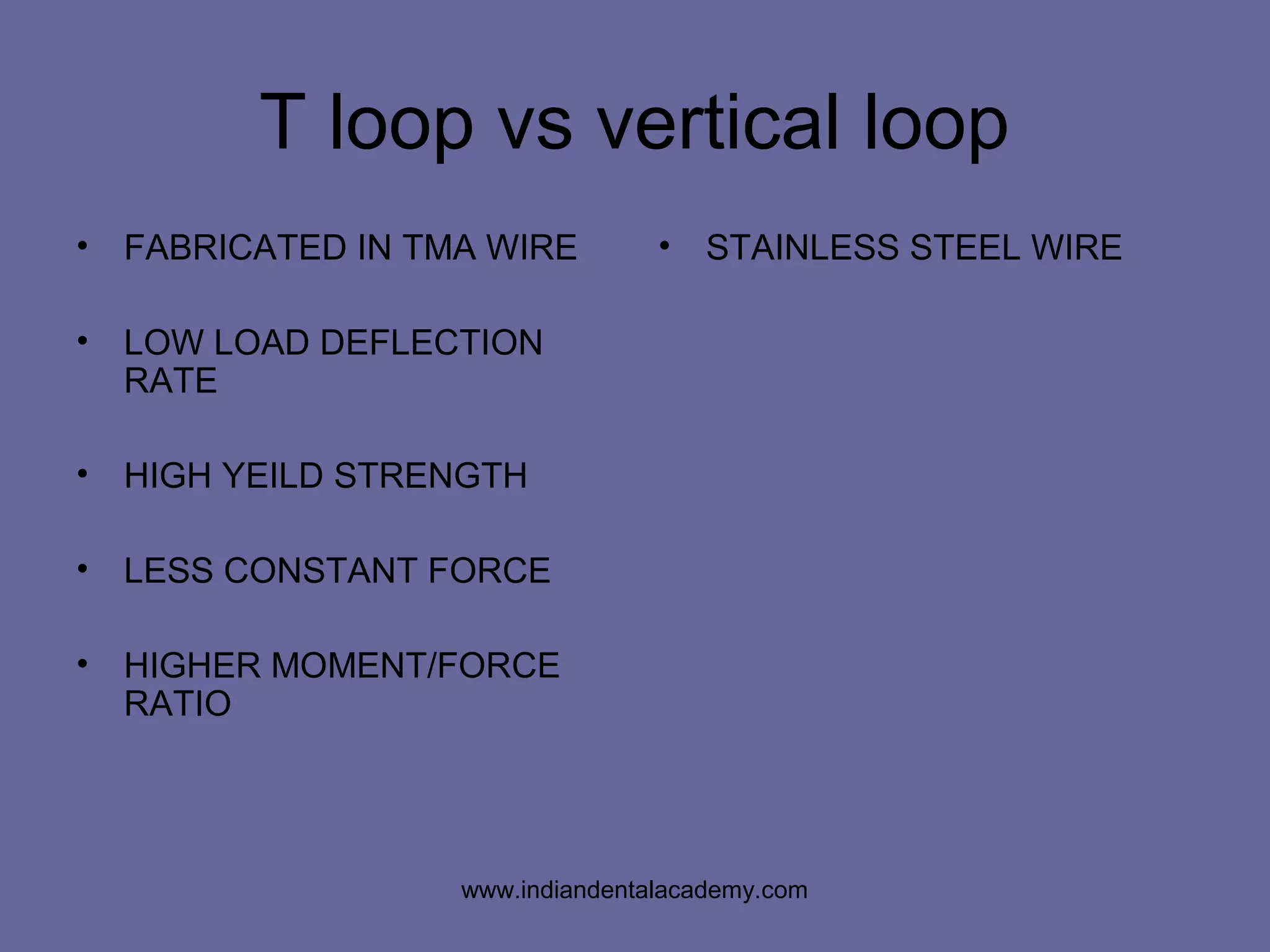
BURSTONE’S
T - loop
www.indiandentalacademy.com
10 mm
5 mm
2 mm
4 mm
ALPHA
(ANTERIOR) SEGMENT
BETA
(POSTERIOR) SEGMENT
www.indiandentalacademy.com
• HOW TO USE T LOOPS FOR EXTRACTION
SPACE CLOSURE
• T-LOOPS vs VERTICAL LOOPS
www.indiandentalacademy.com
HOW TO USE T LOOPS FOR
EXTRACTION SPACE CLOSURE
• POSITIONING OF THE LOOP DURING
SPACE CLOSURE
www.indiandentalacademy.com
• IN GROUP A ANCHORAGE PLACE
THE TLOOP
a)offcentered towards anteriors
b)offcentered towards posteriors
c)centered
d)any of the above position
www.indiandentalacademy.com
• What are preactivation bends? why are
they given?
www.indiandentalacademy.com
BIOMECHANICS
• STATIC EQULIBRIUM PRINCIPLE
www.indiandentalacademy.com
• What is moment to force ratio? What is its
significance?
www.indiandentalacademy.com
Consider the moment created when force is applied Mf and the
counter balancing moment generated by the couple within the
bracket Mc
Mc/Mf = 0 –Pure tipping Crot and cres same,thus the
tooth rotates around the Cres
0 < Mc/Mf >1- Controlled tipping – Crot displaced away
from Cres – crown and root move in the same direction
Mc/Mf = 1– Bodily movement – equal movement of crown
and root
Mc/Mf > 1 Torque – root apex moves further than thewww.indiandentalacademy.com
M/F 5 : 1 Uncontrolled tipping
M/F 8 : 1 Controlled tipping
M/F 10 : 1 Translation
M/F >10 : 1 Root movement
MOMENT TO FORCE RATIO FOR VARIOUS
TOOTH MOVEMENTS
www.indiandentalacademy.com
Off center bend
Points in the direction
of the force produced
on the tooth
Center bend
Short segmentLong segment
Points in the direction
opposite of the force
produced on tooth
No short or long
segment
No force produced
V - BEND
PRINCIPLE
www.indiandentalacademy.com
T loop vs vertical loop
• FABRICATED IN TMA WIRE
• LOW LOAD DEFLECTION
RATE
• HIGH YEILD STRENGTH
• LESS CONSTANT FORCE
• HIGHER MOMENT/FORCE
RATIO
• STAINLESS STEEL WIRE
www.indiandentalacademy.com
GROUP B ANCHORAGE
Distal force on anteriors Mesial forces on posteriors
Equal potential for tooth mvt.
Alpha moment Beta moment
Horizontal force acting on both segments are same
Moment to force ratio
EQUAL
EQUAL
RETRACTION OF ANTERIOR
PROTRACTION OF POSTERIOR
www.indiandentalacademy.com
Group B ANCHORAGE CASE
www.indiandentalacademy.com
• POSITION OF T-LOOP:
D = L-A
2
D = Distance from the center of the loop to
either the anterior bracket or posterior
auxillary tube.
L = Distance between the canine bracket
and Molar tube.
A = The millimeters of activation of the
spring (usually 6 mm)
www.indiandentalacademy.com
αβ
www.indiandentalacademy.com
GROUP A ANCHORAGE
Distal force on anteriors Mesial forces on posteriors
Maximum potential for tooth mvt. Miminised or counteracted
Decrease moment Increase moment
Horizontal force acting on both segments are same
Moment to force ratio
Reactive unit Anchor unitwww.indiandentalacademy.com
Alpha moment Beta moment
Anteriors posteriors
Vertical forces created
Extrusion
When unequal or unbalanced
Intrusion
alpha
beta
alpha
beta
Intrusion Extrusion
www.indiandentalacademy.com
• GIVE EQUAL ALPHA AND BETA BENDS AND PLACE
THE LOOPS OFFCENTERED TOWARDS
POSTERIORS
• GIVE MORE BETA BEND AND PLACE THE LOOP
OFFCENTERED TOWARDS ANTERIORS
• GIVE EQUAL ALPHA AND BETA BENDS AND PLACE
THE LOOPS AT CENTER AND USE HEADGEAR TO
CONTROL THE POSTERIOR SEGMENT
www.indiandentalacademy.com
T LOOP The preactivated spring with the anti tip
and anti rotation BENDS ARE placed
Activation on insertion is 6mm
The m/f is 8:1 – controlled tipping
Now as the tooth moves the activation
reduced to 4mm – the force is reduced
M/f ratio is increased - bodily movement further
The activation is reduced to 2mm – force is
further reduced
M/f ratio increased – 12:1
Root uprighting
www.indiandentalacademy.com
ANTI RATIONAL BENDS-
OPTIONAL
www.indiandentalacademy.com
THANK YOU
www.indiandentalacademy.com

Burstone’s T Loop

  • 1.
  • 2.
    10 mm 5 mm 2mm 4 mm ALPHA (ANTERIOR) SEGMENT BETA (POSTERIOR) SEGMENT www.indiandentalacademy.com
  • 3.
    • HOW TOUSE T LOOPS FOR EXTRACTION SPACE CLOSURE • T-LOOPS vs VERTICAL LOOPS www.indiandentalacademy.com
  • 4.
    HOW TO USET LOOPS FOR EXTRACTION SPACE CLOSURE • POSITIONING OF THE LOOP DURING SPACE CLOSURE www.indiandentalacademy.com
  • 5.
    • IN GROUPA ANCHORAGE PLACE THE TLOOP a)offcentered towards anteriors b)offcentered towards posteriors c)centered d)any of the above position www.indiandentalacademy.com
  • 6.
    • What arepreactivation bends? why are they given? www.indiandentalacademy.com
  • 7.
    BIOMECHANICS • STATIC EQULIBRIUMPRINCIPLE www.indiandentalacademy.com
  • 8.
  • 9.
    • What ismoment to force ratio? What is its significance? www.indiandentalacademy.com
  • 10.
  • 11.
    Consider the momentcreated when force is applied Mf and the counter balancing moment generated by the couple within the bracket Mc Mc/Mf = 0 –Pure tipping Crot and cres same,thus the tooth rotates around the Cres 0 < Mc/Mf >1- Controlled tipping – Crot displaced away from Cres – crown and root move in the same direction Mc/Mf = 1– Bodily movement – equal movement of crown and root Mc/Mf > 1 Torque – root apex moves further than thewww.indiandentalacademy.com
  • 12.
    M/F 5 :1 Uncontrolled tipping M/F 8 : 1 Controlled tipping M/F 10 : 1 Translation M/F >10 : 1 Root movement MOMENT TO FORCE RATIO FOR VARIOUS TOOTH MOVEMENTS www.indiandentalacademy.com
  • 13.
  • 14.
    Off center bend Pointsin the direction of the force produced on the tooth Center bend Short segmentLong segment Points in the direction opposite of the force produced on tooth No short or long segment No force produced V - BEND PRINCIPLE www.indiandentalacademy.com
  • 15.
  • 16.
  • 17.
  • 18.
  • 19.
    T loop vsvertical loop • FABRICATED IN TMA WIRE • LOW LOAD DEFLECTION RATE • HIGH YEILD STRENGTH • LESS CONSTANT FORCE • HIGHER MOMENT/FORCE RATIO • STAINLESS STEEL WIRE www.indiandentalacademy.com
  • 20.
  • 21.
  • 22.
  • 23.
    GROUP B ANCHORAGE Distalforce on anteriors Mesial forces on posteriors Equal potential for tooth mvt. Alpha moment Beta moment Horizontal force acting on both segments are same Moment to force ratio EQUAL EQUAL RETRACTION OF ANTERIOR PROTRACTION OF POSTERIOR www.indiandentalacademy.com
  • 24.
    Group B ANCHORAGECASE www.indiandentalacademy.com
  • 25.
    • POSITION OFT-LOOP: D = L-A 2 D = Distance from the center of the loop to either the anterior bracket or posterior auxillary tube. L = Distance between the canine bracket and Molar tube. A = The millimeters of activation of the spring (usually 6 mm) www.indiandentalacademy.com
  • 26.
  • 27.
  • 28.
    GROUP A ANCHORAGE Distalforce on anteriors Mesial forces on posteriors Maximum potential for tooth mvt. Miminised or counteracted Decrease moment Increase moment Horizontal force acting on both segments are same Moment to force ratio Reactive unit Anchor unitwww.indiandentalacademy.com
  • 29.
    Alpha moment Betamoment Anteriors posteriors Vertical forces created Extrusion When unequal or unbalanced Intrusion alpha beta alpha beta Intrusion Extrusion www.indiandentalacademy.com
  • 30.
    • GIVE EQUALALPHA AND BETA BENDS AND PLACE THE LOOPS OFFCENTERED TOWARDS POSTERIORS • GIVE MORE BETA BEND AND PLACE THE LOOP OFFCENTERED TOWARDS ANTERIORS • GIVE EQUAL ALPHA AND BETA BENDS AND PLACE THE LOOPS AT CENTER AND USE HEADGEAR TO CONTROL THE POSTERIOR SEGMENT www.indiandentalacademy.com
  • 31.
  • 32.
    T LOOP Thepreactivated spring with the anti tip and anti rotation BENDS ARE placed Activation on insertion is 6mm The m/f is 8:1 – controlled tipping Now as the tooth moves the activation reduced to 4mm – the force is reduced M/f ratio is increased - bodily movement further The activation is reduced to 2mm – force is further reduced M/f ratio increased – 12:1 Root uprighting www.indiandentalacademy.com
  • 33.
  • 34.
  • 35.