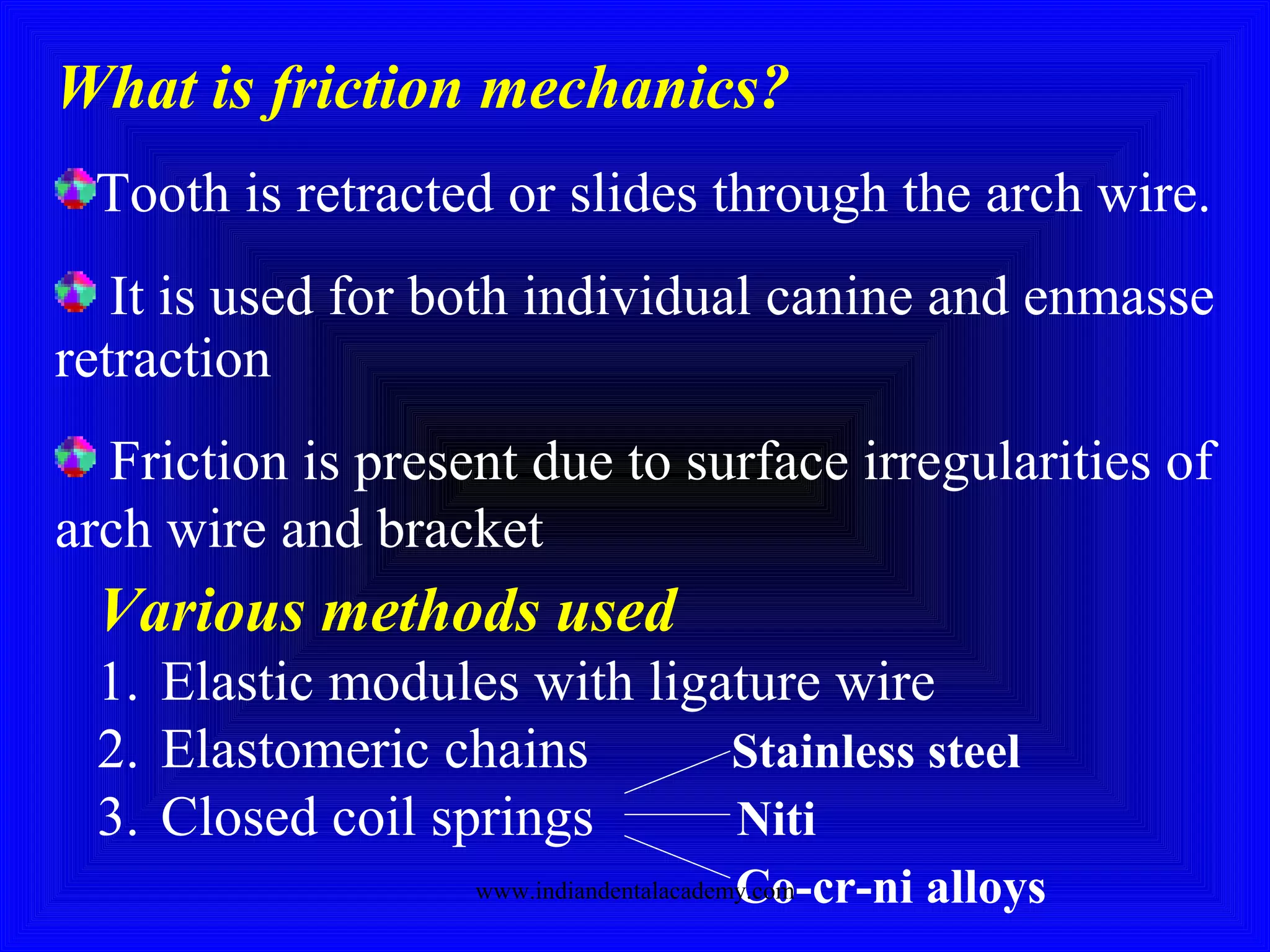
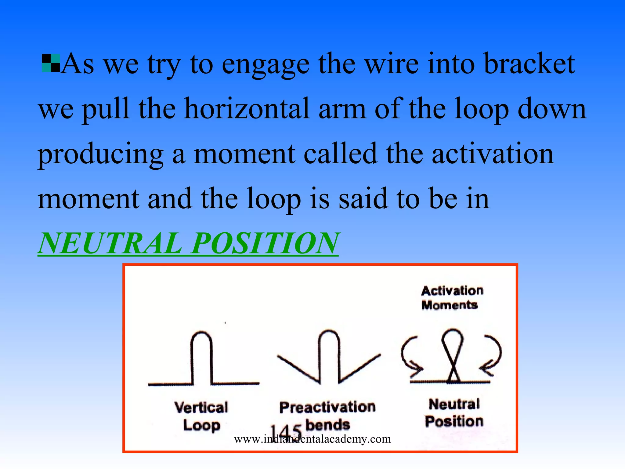
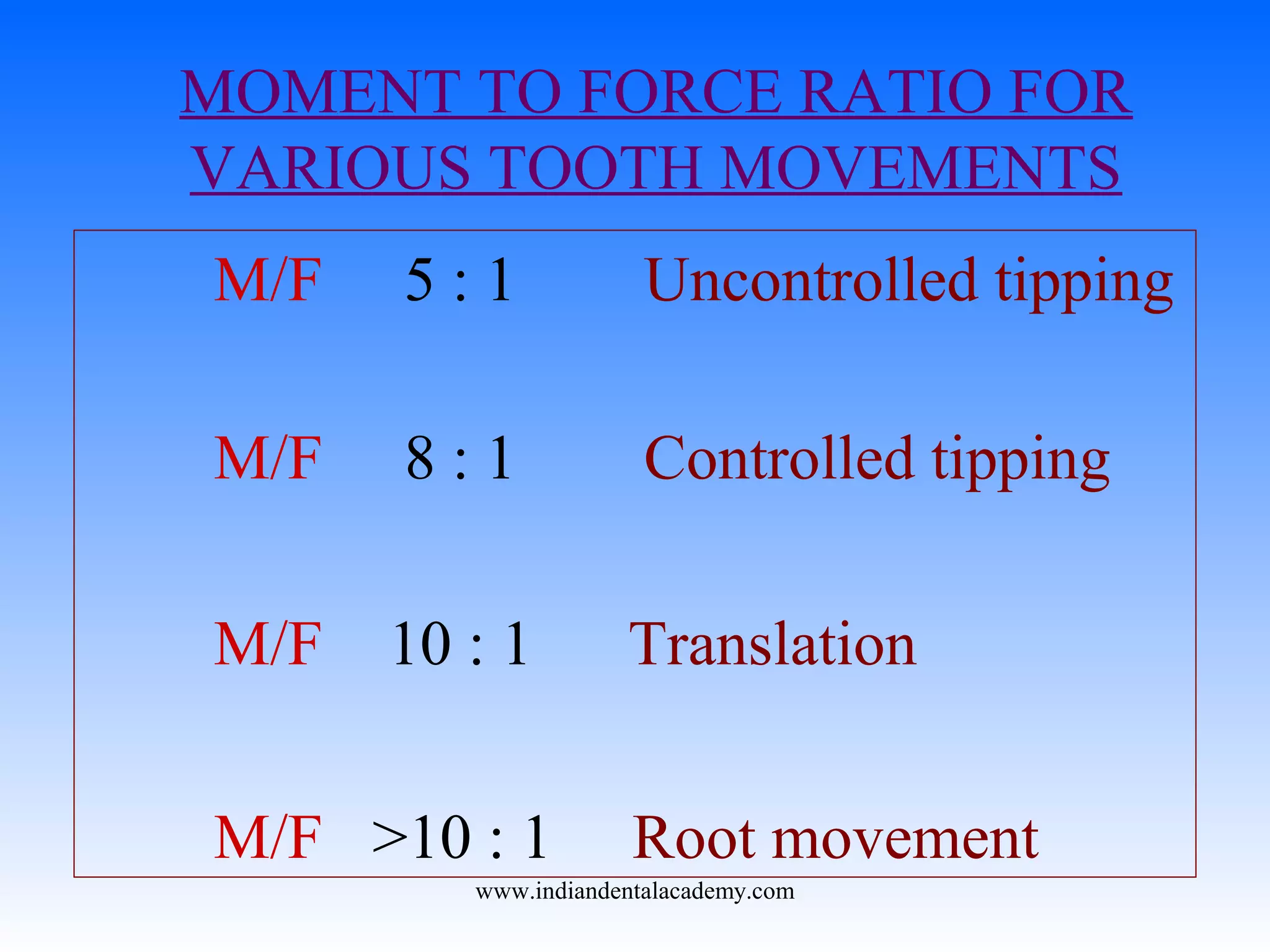
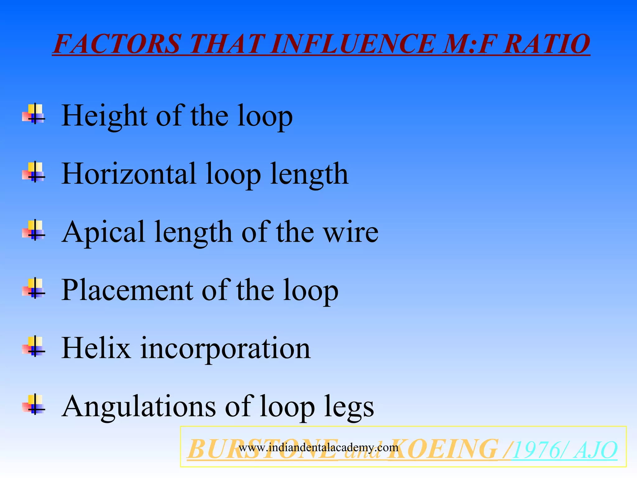
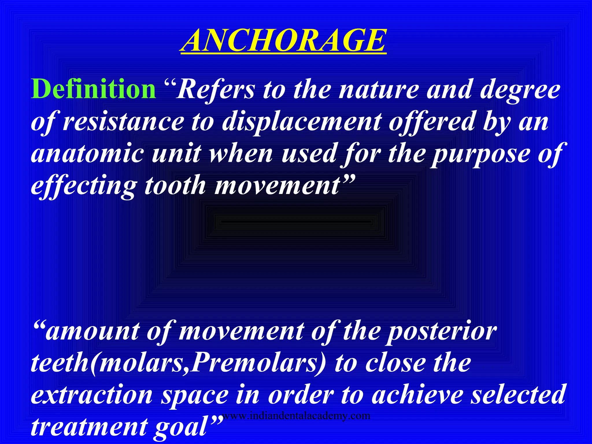
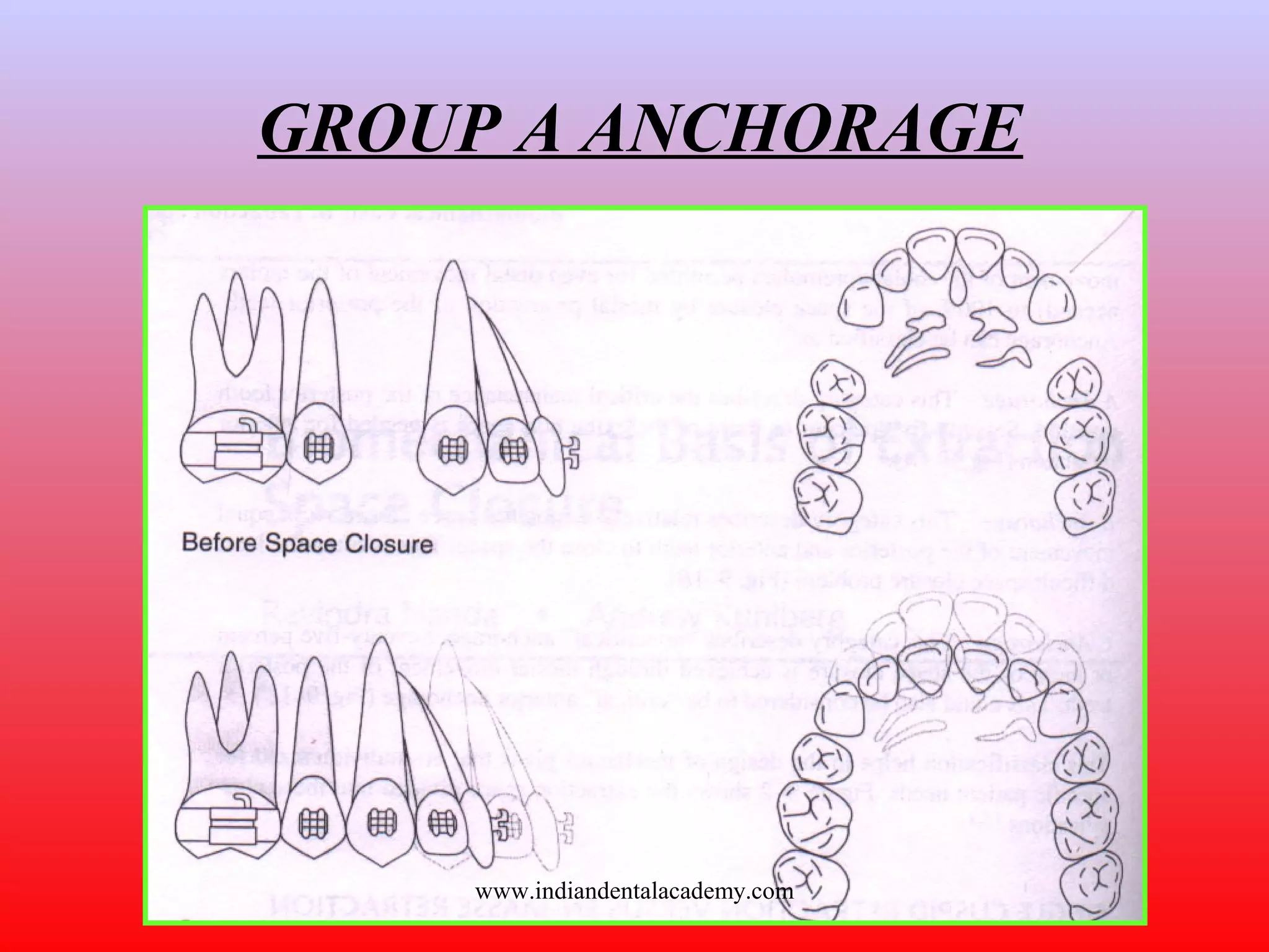
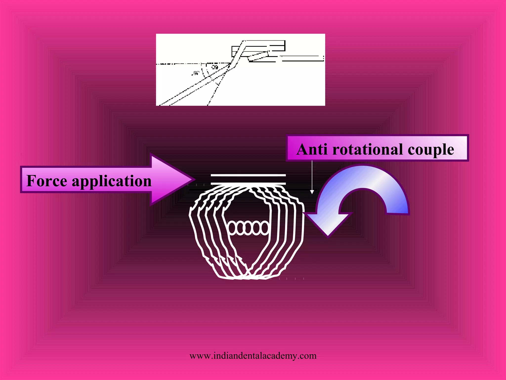
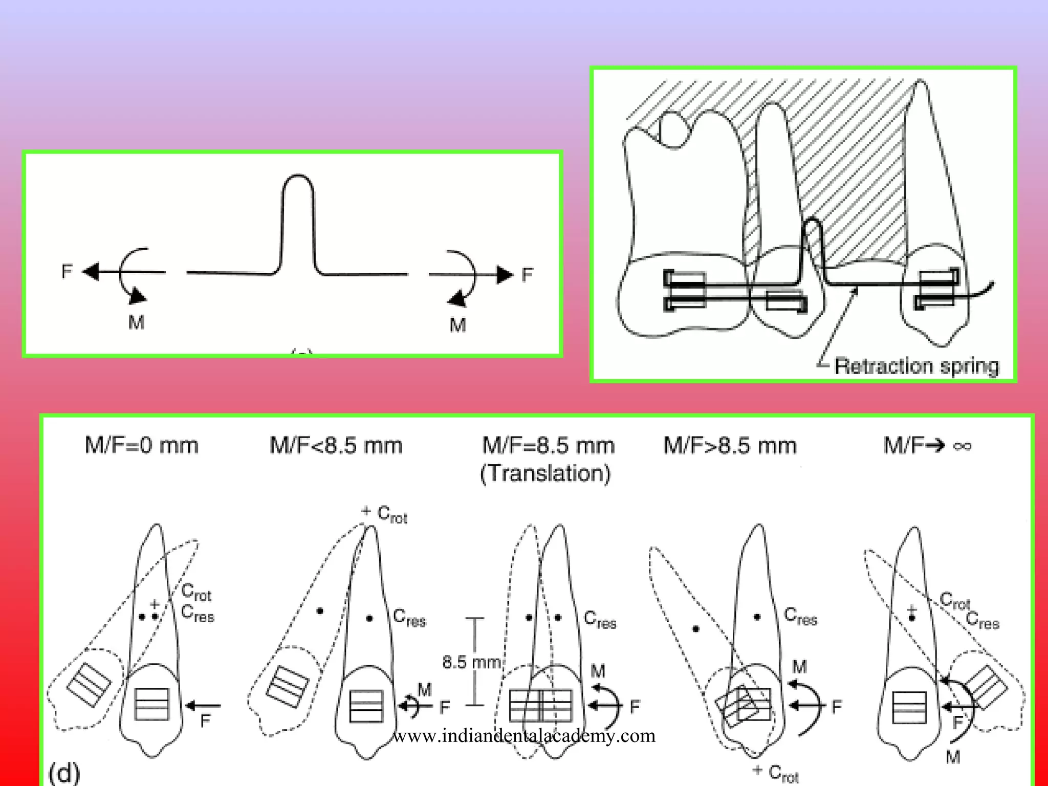
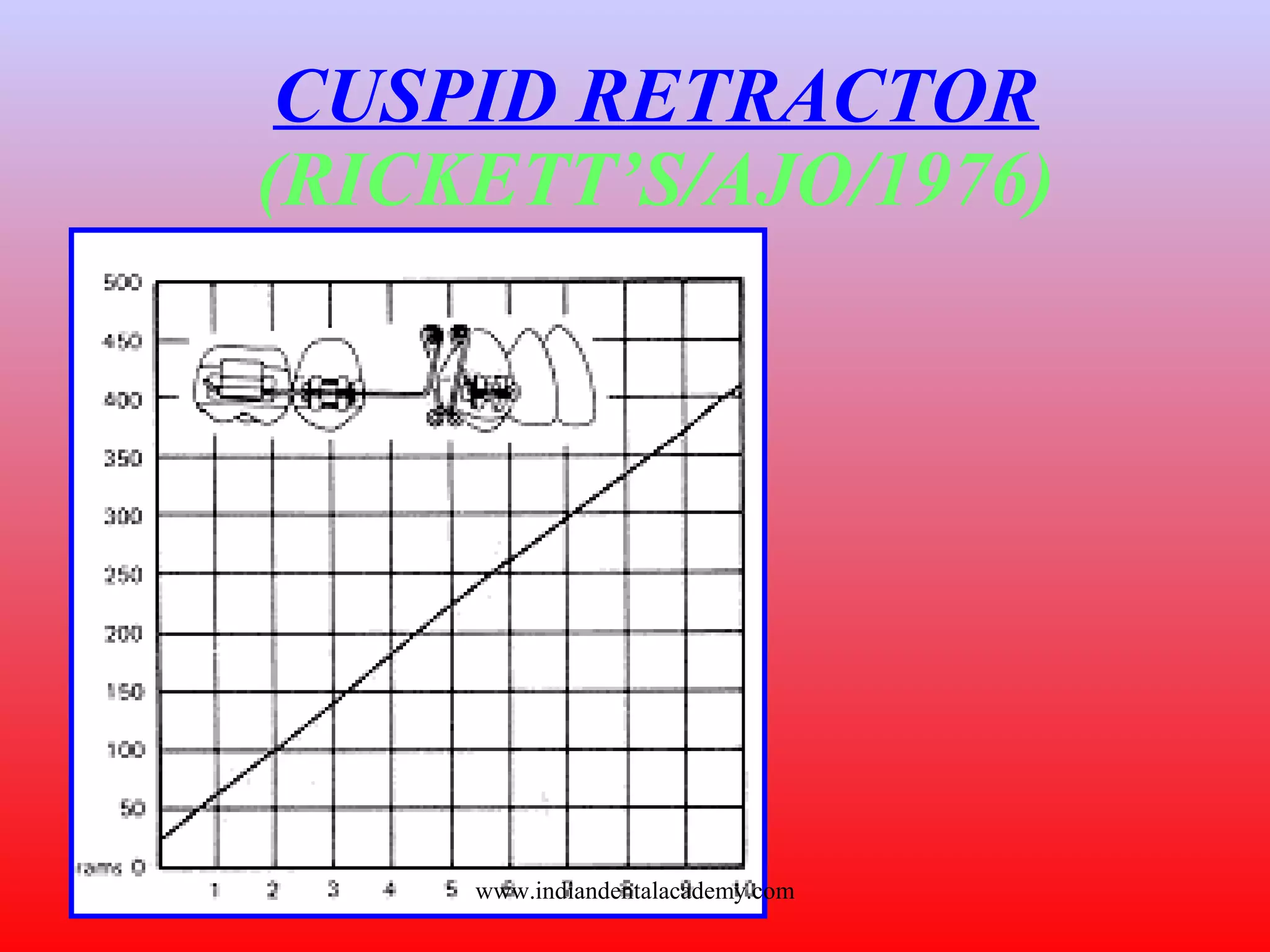
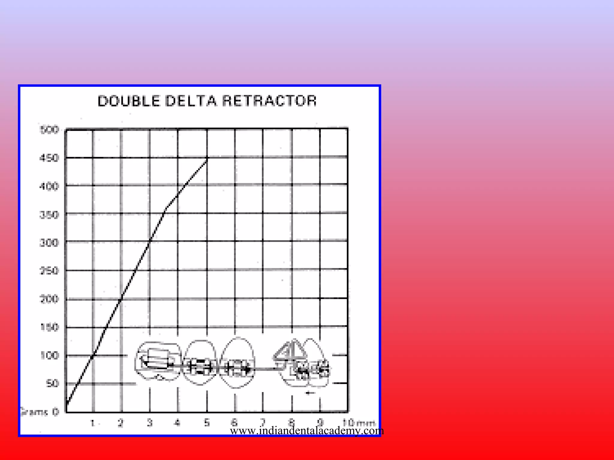
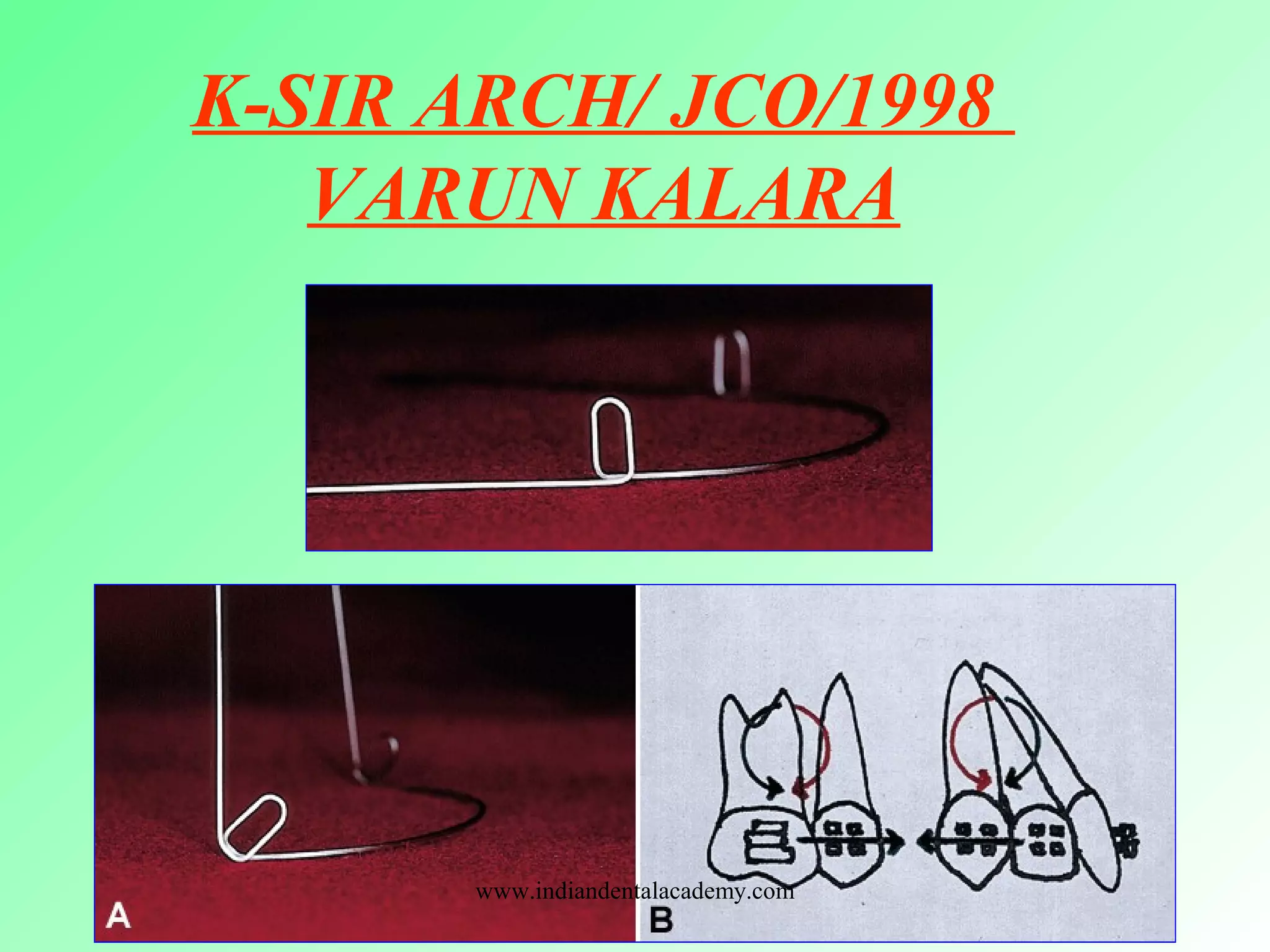
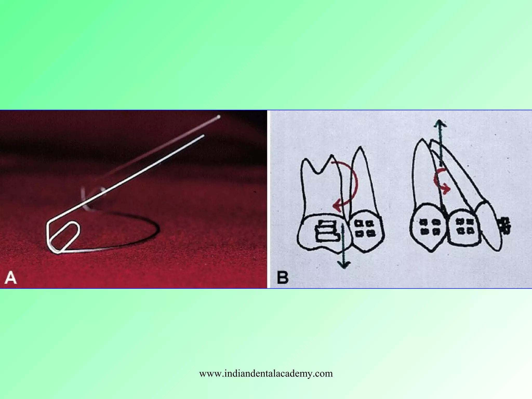
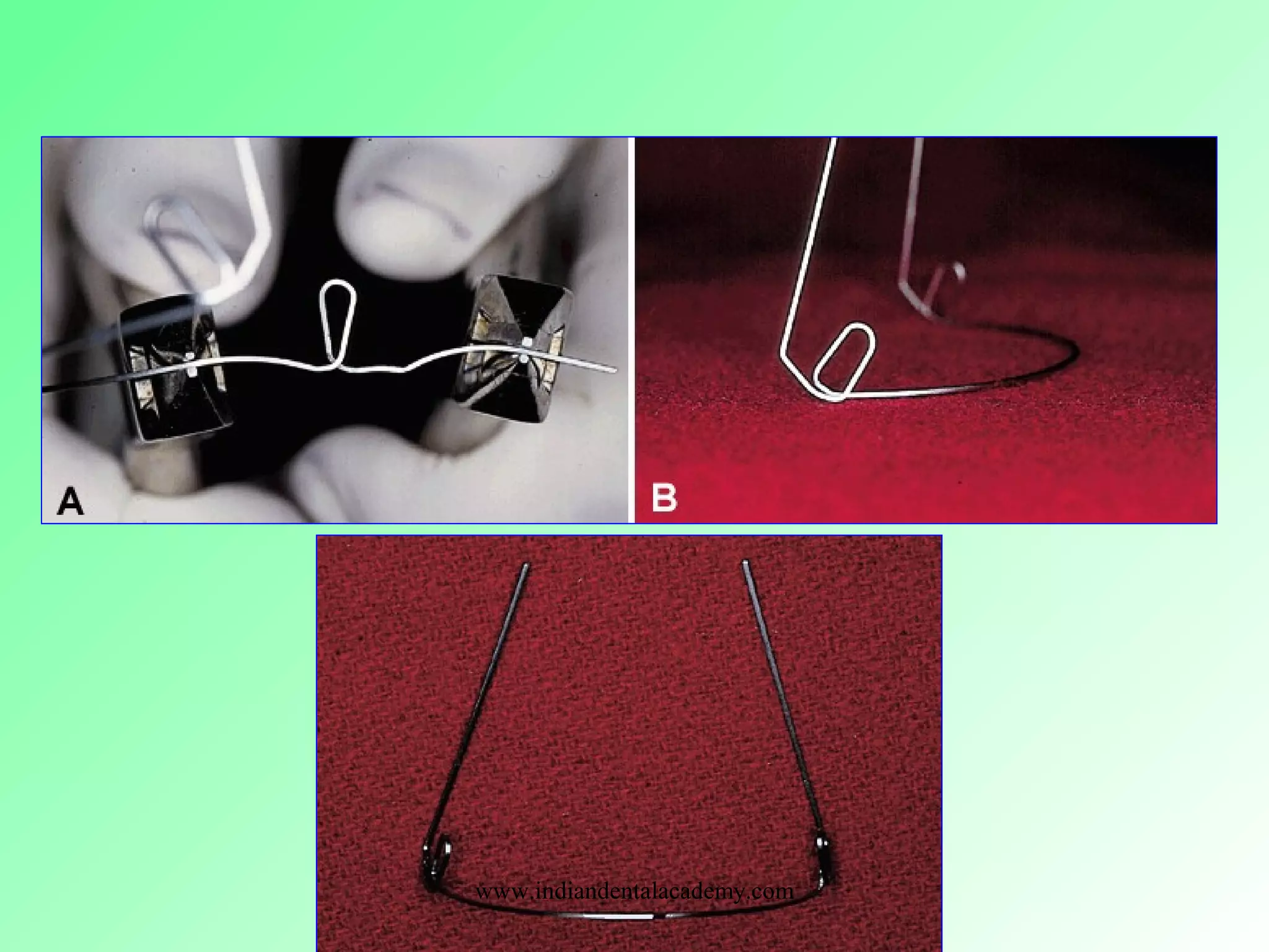
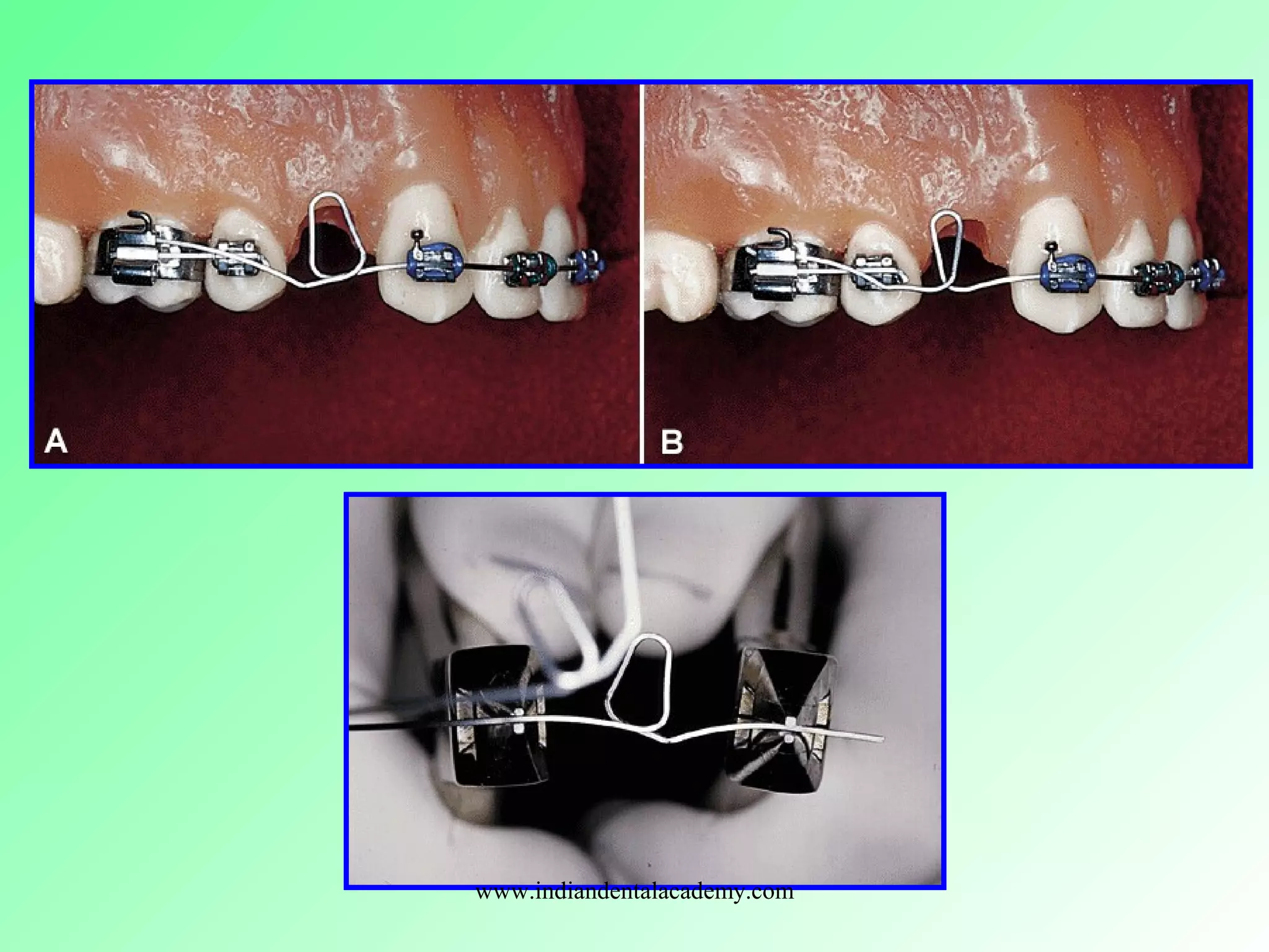
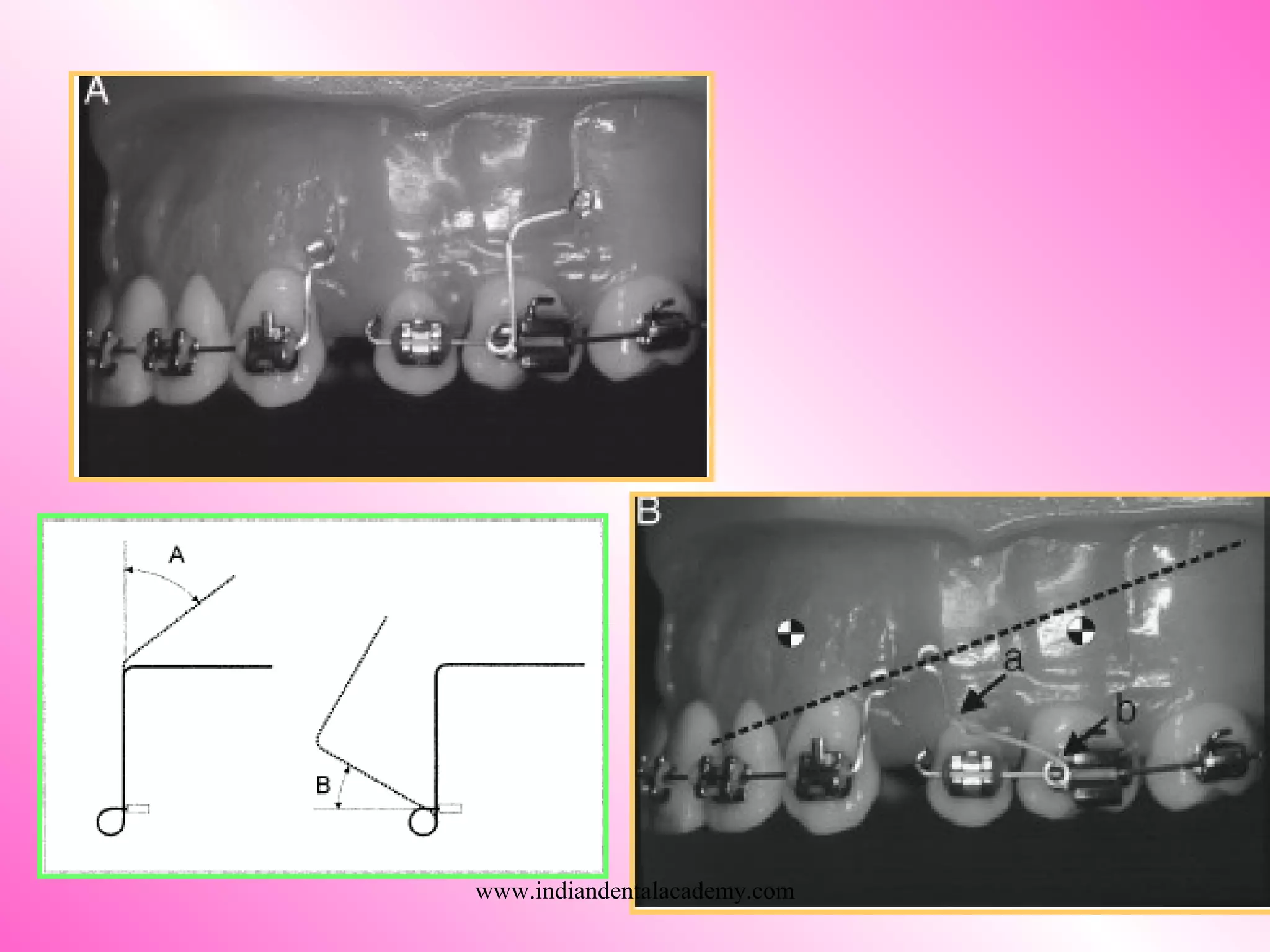
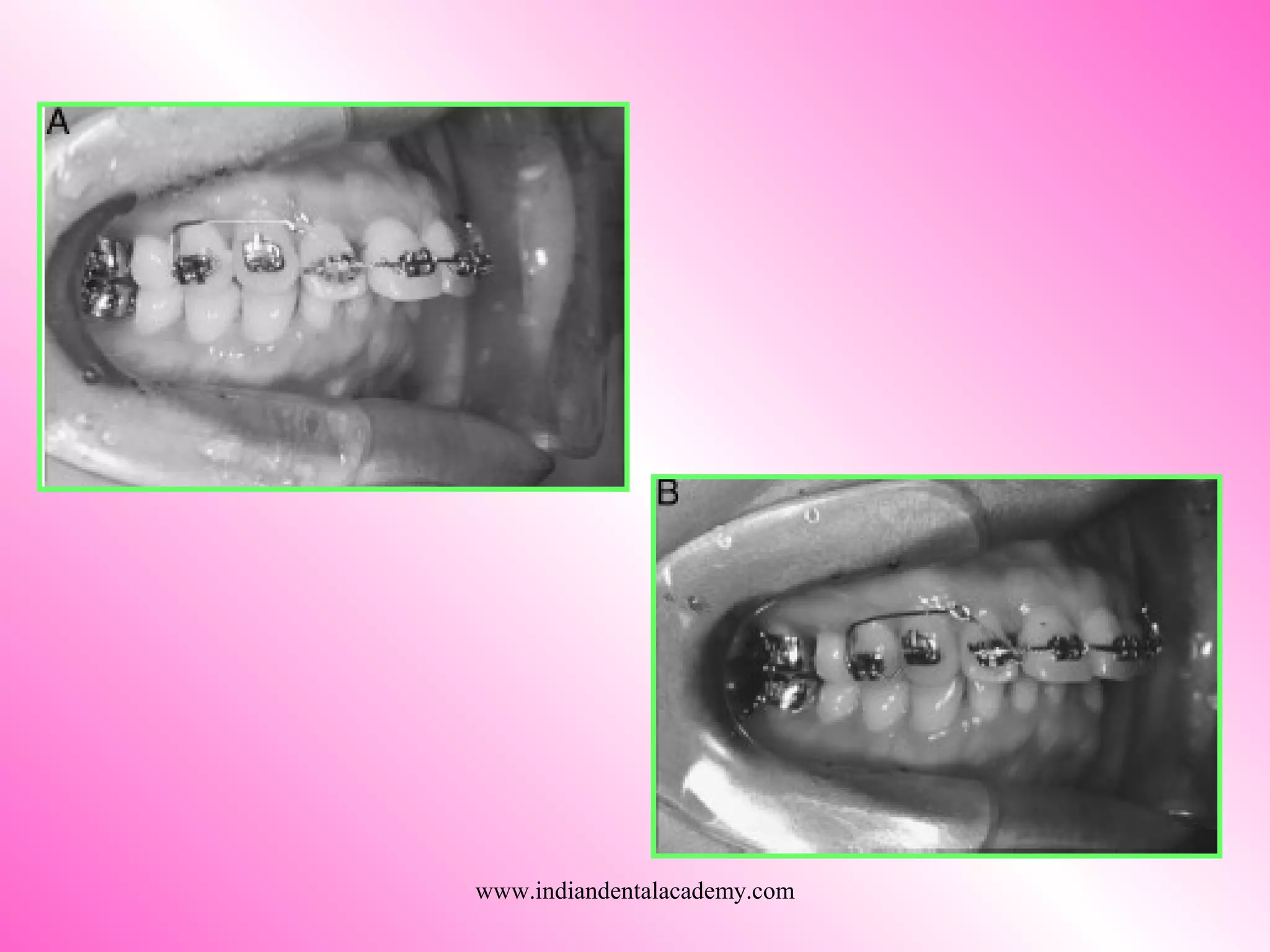
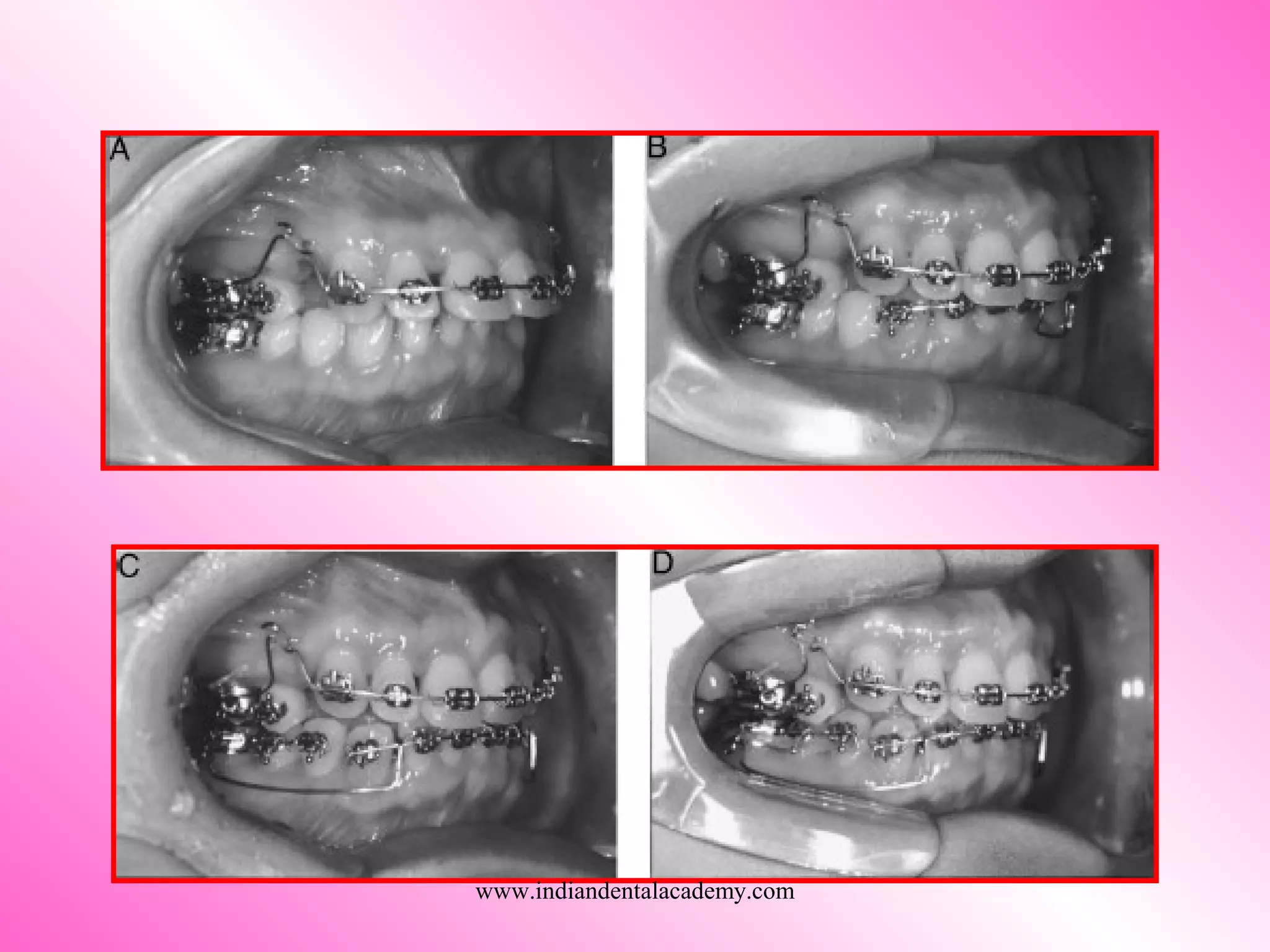
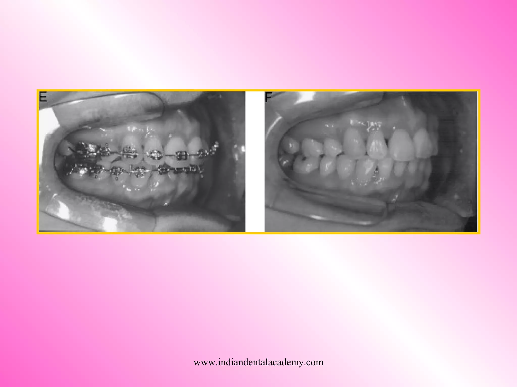
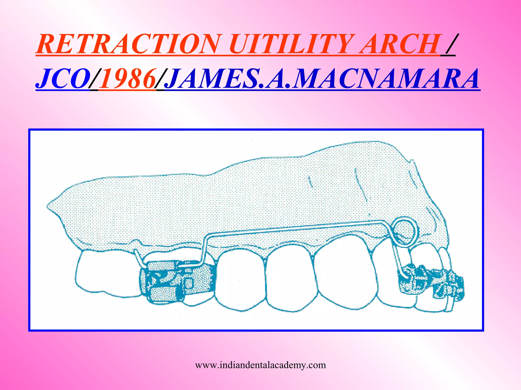
www.indiandentalacademy.com
INTRODUCTION
Tooth movement occurs by various
mechanisms
EXTRENSIC
Force is basic component
Extrinsic - elastics, E-chain,Niti springs e.t.c
Intrinsic - Loops bend in arch wire
INTRINSIC
www.indiandentalacademy.com
EVOLUTION
As early as 1915 (in first issue of I.J.O),
Ray.D.Robinson demonstrated about
Efficiency of loop arch wire
Dr.Robert H.W Strang (1933) pioneered
the loop design for edgewise mechanics
On the other hand Dr.P.R.Begg (1952)
advocated their usage in the initial phase of
Begg treatment www.indiandentalacademy.com
With advancement in techniques of
scientific testing and better
understanding of physiological
principles of tooth movement
improvisation of loop design continued
through 60’s and 70’s
Eminent orthodontist like Dr.Joseph
Jarabak,Dr.Charles Burstone,
Dr.Robert Ricketts must be credited for
their single contributionswww.indiandentalacademy.com
CENTER OF MASS
Each body has point in its mass
Which we call center of mass in
Gravity-free environment.
CENTER OF GRAVITY
In an environment where
Gravity is present
www.indiandentalacademy.com
FORCE-It is defined as “An act upon a body
that changes or tends to change the state of
rest or the motion of that body”.
by :R.J NIKOLAI
www.indiandentalacademy.com
CENTER OF ROTATION
 Line drawn through long axis
of initial and final tooth
movement where it meets is
called center of rotation
 It can be at 1.At CR
2.Apical to CR
3.At root apex
4.At infinity
 Tooth movement will depend
on the location of center of
rotation
www.indiandentalacademy.com
CENTER OF RESISTANCE
Depends on alveolar bone
support,root length,no. of
roots.It is at the approximate
mid point of embedded
portion of root.
POINT OF FORCE APPLICATION
www.indiandentalacademy.com
Defined as the rotational tendency when force is
applied away from the center of resistance
A force acting at a distance
Mathematically given as M = f x d
Where M is the moment F is the force
And D is the perpendicular distance of the line
of action to the center of resistance
MOMENT
www.indiandentalacademy.com
Direction of a moment
The direction of the moment of a force can be
determined by continuing the line of action
around the center of resistance towards the
point of origin.
www.indiandentalacademy.com
COUPLE-It is two parallel
forces of equal magnitude
acting in opposite direction
and separated by a distance.
MOMENT OF COUPLE
It is the product of one of
the force times the distance
between two forces
www.indiandentalacademy.com
MAXILLARY CENTRAL
INCISOR
CENTER OF RESISTANCE
AND M:F FOR INDIVIDUAL
TOOTH TRANSLATION
www.indiandentalacademy.com
MAXILLARY LATERAL
INCISOR
www.indiandentalacademy.com
MAXILLARY CANINE
www.indiandentalacademy.com
MAXILLARY MOLAR
www.indiandentalacademy.com
MANDIBULAR INCISOR
www.indiandentalacademy.com
MANDIBULAR CANINE
www.indiandentalacademy.com
MANDIBULAR MOLAR
www.indiandentalacademy.com
C:R FOR OF ANRERIOR
AND POSTERIOR SEGMENT
www.indiandentalacademy.com
What is friction mechanics?
Tooth is retracted or slides through the arch wire.
It is used for both individual canine and enmasse
retraction
Friction is present due to surface irregularities of
arch wire and bracket
Various methods used
1. Elastic modules with ligature wire
2. Elastomeric chains Stainless steel
3. Closed coil springs Niti
Co-cr-ni alloyswww.indiandentalacademy.com
4. J hook head gear
5.Mulligan V bend sliding mechanics
6.Employing tip-Edge brackets on canines.
Disadvantages of sliding mechanics
1. It gives variable force.
2. E-chain absorbs water and saliva when exposed
to oral environment causing degradation of force
by 50%-70% by 1st
day
3. Excess Stretching of E-chain causes breakdown
of internal bond leading permanent deformation.
4. Permanent staining of E-chainwww.indiandentalacademy.com
5.Dependent on patient cooperation in case of
elastic bands
6.Due to friction and binding between bracket and
arch wire applied force should be higher than the
required optimum force because of decay in force
Due to all these problems in friction or
sliding mechanics frictionless mechanics
stands in better position for retraction ,as
monitoring of optimum force can be done
effectively and it is active for a longer
duration of time.www.indiandentalacademy.com
What is frictionless mechanics?
Force generated intrinsically by arch wire
By in cooperating loops in arch wire
Energy is stored in loops and release it in slow
and continuous fashion
There is no friction between archwire and
bracket
www.indiandentalacademy.com
BIOMECHANICS FOR
FRICTIONLESS MECHANICS
The teeth in an arch wire will invariably
assumes the passive position of the arch wire.
When we place bend in the middle of the
wire and engage into bracket two equal and
opposite moments are produced
www.indiandentalacademy.com
When offset bend is placed differential force is
produced.
This same principles apply in FRICTIONLESS
mechanics where instead of bend loop is placed
in the wire.
www.indiandentalacademy.com
Bends placed on the mesial and distal legs of
loop are called as ALPHA and BETA
respectively
These bends produce ALPHA and BETA
moments when wire is placed into bracket
MESIAL LEGDISTAL LEG
www.indiandentalacademy.com
Activating the loops produces the forces
in frictionless mechanics.Pulling the distal
end of the arch wire through molar tube and
cinching it back does this.
According to CHARLES BURSTONE
moment to force ratio for translation is about
10:1,a regular 10mm high vertical loop offers a
M:F ratio of only 3:1 when it is activated by
1mm. www.indiandentalacademy.com
To get M:F ratio of 10:1 activation should
be reduced to .2mm,but force level is not
sufficient for retraction
In order to increase moment,height can be
increased but it has limitation as available
space in the vestibule
www.indiandentalacademy.com
The most effective way to increase M:F
ratio is placing PRE ACTIVATION BENDS
OR GABLE Bends.
These bends can be placed within the loops
or where loop meets the arch wire.
www.indiandentalacademy.com
As we try to engage the wire into bracket
we pull the horizontal arm of the loop down
producing a moment called the activation
moment and the loop is said to be in
NEUTRAL POSITION
www.indiandentalacademy.com
Thus with this added moment M:F ratio of
loop is increased.
The ALPHA MOMENT produces distal
root movement of anterior teeth,while the
BETA MOMENT produces mesial root
movement of posterior teeth.
If ALPHA = BETA NO VERTICAL FORCE
If ALPHA not BETA ,VERTICAL FORCE
www.indiandentalacademy.com
If BETA moment is >ALPHA posterior anchorage
is enhanced by the mesial root movement of
posterior teeth and net extrusive effect on posteriors
and intrusive force on anterior teeth.
If ALPHA moment is > BETA anchorage of
anterior segment is increased by distal root
movement and net extrusive effect on anterior teeth
and intrusive effect on posterior.
www.indiandentalacademy.com
The M:F ratio increases as spring gets
deactivated
Spring should not be activated too
frequently
www.indiandentalacademy.com
MOMENT TO FORCE RATIO FOR
VARIOUS TOOTH MOVEMENTS
M/F 5 : 1 Uncontrolled tipping
M/F 8 : 1 Controlled tipping
M/F 10 : 1 Translation
M/F >10 : 1 Root movement
www.indiandentalacademy.com
FACTORS THAT INFLUENCE M:F RATIO
Height of the loop
Horizontal loop length
Apical length of the wire
Placement of the loop
Helix incorporation
Angulations of loop legs
BURSTONE and KOEING /1976/ AJOwww.indiandentalacademy.com
ANCHORAGE
Definition “Refers to the nature and degree
of resistance to displacement offered by an
anatomic unit when used for the purpose of
effecting tooth movement”
“amount of movement of the posterior
teeth(molars,Premolars) to close the
extraction space in order to achieve selected
treatment goal”
www.indiandentalacademy.com
ANCHORAGE CLASSIFICATION
According to Ravindra Nanda
GROUP A
GROUP B
GROUP C
www.indiandentalacademy.com
GROUP A ANCHORAGE
www.indiandentalacademy.com
GROUP B ANCHORAGE
www.indiandentalacademy.com
GROUP C ANCHORAGE
www.indiandentalacademy.com
FACTORS DETERMINING THE TOOTH
MOVEMENT REQUIRED DURING
SPACE CLOSURE
AMOUNT OF CROWDING
-Extractions are Usually done to relive crowding
-Anchorage control becomes very crucial
-Maintaining anchorage while creating space
for decrowding is importantwww.indiandentalacademy.com
ANCHORAGE
-Anchorage classification during treatment
planning is very important for desired results.
various methods like (headgear,lip-
bumper,lingual-arch,trans palatal arch e.t.c)
AXIAL INCLINATION
-Inclination of canine and incisor are
particularly important.
-when same force and moment applied to a
tooth or a group of teeth with different axial
inclination will result in different type of tooth
movement
www.indiandentalacademy.com
-example in case of unfavorable positioned
canine(root mesial crown distal)
MIDLINE DISCREPANCIES AND LEFT
OR RIGHT ASYMMETRIES
-These problems should corrected as early as
possible
-Asymmetric forces could result in unilateral vertical
forces causing asymmetric anchorage losswww.indiandentalacademy.com
VERTICAL DIMENSION
-Attention should be given to vertical forces during
space closure .
-undesirable vertical extrusive forces may result in
increased lower facial height,increased inter labial
gap,excessive gingival display
www.indiandentalacademy.com
RETRACTION
STAGEDENMASSE
FRICTIONLESS SLIDING
SIMULTANEOUS
INTRUSION
AND RETRACTION
STAGE 1 STAGE 2
CANINE ANTERIORS
FRICTIONLESS SLIDING
FRICTIONLESS
SLIDING
TIP AND UPRIGHT
www.indiandentalacademy.com
Mechanism of action of retraction
Key hole loop
(frictionless)
Cl-3 elastic
(friction)
Individual
Canine
retraction
www.indiandentalacademy.com
SPACE CLOSING LOOPS
Closing loop arch wires should be fabricated
from rectangular wire to prevent wire from rolling
in the bracket slot
The performance of the loop,from the
perspective
of engineering theory,is determined by 4 major
characteristics
1. Spring properties
2. Moment it generates
3. Its location
4. Additional design principle
www.indiandentalacademy.com
1. SPRING PROPERTIES
 It is determined almost totally by the
A. wire material
B. size of the wire
C. distance between point of attachment
 Changing the size of the wire produce
largest change in its characteristics,but the
amount of wire incorporated in the loop is
also importantwww.indiandentalacademy.com
www.indiandentalacademy.com
2.Moment it generates
To close an extraction space while
producing bodily tooth movement closing
loop must generate not only closing force but
also approximate MOMENT
www.indiandentalacademy.com
To generate a moment limits the amount of
wire that can be incorporated into it,which will
make it more springier and it will unable to
generate necessary MOMENT
MOMENT
www.indiandentalacademy.com
3.Its location
Its location is very important for its
performance in closing space.
As gable bends are incorporated,the
closing loops functions as the V bend in
the arch wire.effect of V bend is very
sensitive to its location
www.indiandentalacademy.com
There can be 3 locations of V bend
1.Equal distance
2.Closure to anterior
3.Closure to Posterior
www.indiandentalacademy.com
4.Additional design principle
FAIL SAFE this means that ,although a
reasonable range of action is desired
from each activation tooth movement
should stop after that.If patient does not
come for scheduled appointment
www.indiandentalacademy.com
Design should be as simple as
possible
During activation of loop it is
considered more effective when it is
closed rather than opened
www.indiandentalacademy.com
INDIVIDUAL CANINE RETRACTION
The canines are key stones of occlusion.
Correct positioning of the canine after
retraction is imperative for function, stability
and esthetics
www.indiandentalacademy.com
• This requires the creation of a bio mechanical
system to deliver a predetermined force and a
relatively constant moment-to-force ratios in
order to avoid distal tipping and rotation.
It is important to do individual canine retraction
in maximum anchorage cases.
www.indiandentalacademy.com
Making it possible to apply predetermined
and precise forces which can meet the
biomechanical requirements for planned
tooth movements.
Friction and binding of the tooth are
eliminated.
Tipping and rotations can be controlled.
www.indiandentalacademy.com
THE CR OF CANINE
Shown to be located in the center of the root
one third of the distance from the alveolar crest
to the apex.
www.indiandentalacademy.com
FOR TRANSLATION OF CANINE
The displacement of canine depends on the
relationship between the line of force and the
center of resistance (CR)
Application of force through CR.
www.indiandentalacademy.com
Force application Distal tipping
www.indiandentalacademy.com
Force application Rotation
www.indiandentalacademy.com
Antitip and antirotation moment-to-force
conditions necessary for translation of
canines with average dimensions.www.indiandentalacademy.com
Force application
Anti tip couple
www.indiandentalacademy.com
Anti rotational couple
Force application
www.indiandentalacademy.com
VARIOUS CANINE RETRACTION
SPRINGS
1. CUSPID RETRACTOR(RICKETT’S/AJO/76)
2. T-LOOP SPRING(BURSTONE/AJO/1976)
3. P.G SPRING (P.GJESSING/AJO/1985)
4. CUSPID RETRACTOR (R.HASKELL/AJO/1990
5. NICKEL TITANIUN CANINE RETRACTION
SPRING(/JCO/2002/YASOO WATANABE)www.indiandentalacademy.com
CUSPID RETRACTOR
(RICKETT’S/AJO/1976)
www.indiandentalacademy.com
T-LOOP SPRING
(BURSTONE/AJO/1976)
www.indiandentalacademy.com
-The preactivated spring with the
anti tip and anti rotation is placed
-Activation on insertion is 6mm
-The m/f is 8:1 – controlled tipping
-Now as the tooth moves the
activation reduced to 4mm – the force
is reduced. www.indiandentalacademy.com
-The activation is reduced to 2mm – force
is further reduced
-M/f ratio increased – 12:1
-M/f ratio is increased - bodily movement
further
www.indiandentalacademy.com
T-LOOP SPRING
(BURSTONE/AJO/1976)
www.indiandentalacademy.com
3-DIMENTIONAL
EFFECTS IN
RETRACTION
APPLIANCE
www.indiandentalacademy.com
POUL GJESSING CANINE
RETRACTION SPRING
(P.GJESSING/AJO/1985)
www.indiandentalacademy.com
CONFIGURATION
It is made from 016x022 inch stainless steel
wire.
With predominant element OVOID DOUBLE
HELIX LOOP extending 10 mm apically, 5.5 mm
width apically.
The smaller occlusal loop with 2 mm diameter,
incorporated to lower the levels of activation.
www.indiandentalacademy.com
Ani tip bend (Alpha) 15˚.
 Beta bend 12˚ for II premolar,
30˚ for I molar.
 Anti rotation bend 35˚.
 Distal sweep for molar.
www.indiandentalacademy.com
PG CANINE RETRACTION
SPRING
Anti rotation bend
Beta bend
Occlusal loop
Anti tip bend
Apical loop
35º
5.5 mm
15º
2 mm
30º
12º
www.indiandentalacademy.com
TEMPLATE
www.indiandentalacademy.com
CUSPID RETRACTOR
(R.HASKELL/AJO/1990)
www.indiandentalacademy.com
NITI CANINE RETRACTION
SPRING
(JCO/2002/ YASOO WATANABE)
www.indiandentalacademy.com
.016 X .022 TITANAL SPRING
www.indiandentalacademy.com
EN-MASSE RETRACTION
It literally means retracting group of teeth
together as a single unit.
As segmented technique developed by
Burstone,
it utilizes loops for space closure for
1.Anterior retraction
2.Symmetric space closure
3.Posterior protractionwww.indiandentalacademy.com
3-PHASES OF TOOTH
MOVEMENT
A.TIPPING
B.TRANSLATION
C.ROOT UPRIGHTING
www.indiandentalacademy.com
En-masse space closure can effectively be
employed in moderate and minimum
anchorage cases
Simultaneous intrusion and retraction of
the anterior teeth,maintaining torque
control may also be employed . However ,
demand on the Anchorage should be
evaluated carefully.www.indiandentalacademy.com
En-masse retraction is done with a
continuous arch wire with one
closing loop each side distal to
cuspid
Differential force technique and
location of loop can be placed
depending on the type of anchorage.
www.indiandentalacademy.com
Various loop designs are available for
retraction and all are having pre-determined
vertical heights ranging from 7-10mm in
vertical direction to keep it closure to center
of resistance of tooth
www.indiandentalacademy.com
VARIOUS RETRACTION ARCH
WIRES BY FRICTIONLESS
MECHANICS
www.indiandentalacademy.com
OPEN VERTICAL LOOP It was
originated by Dr.Robert.W.Strang(1933).
It was used for retraction of anterior teeth.
CLOSED VERTICAL LOOP
Only being difference is
horizontal overlapping.
www.indiandentalacademy.com
BULL LOOP Dr. Harry bull (1951)
introduced a variation of standard vertical loop
Loops legs were tightly abutting each other
He recommended that these loops should be
made from .0215x .025stainless steel
www.indiandentalacademy.com
VERTICAL OPEN LOOP
WITH HELIX
www.indiandentalacademy.com
OMEGA LOOP
www.indiandentalacademy.com
DELTA LOOP
www.indiandentalacademy.com
CLOSED VERTICAL LOOP WITH
HELIX (MORRIS STONER/1975)
www.indiandentalacademy.com
‘T’ LOOP FOR ENMASSE
RETRACTION AND INTRUSION
www.indiandentalacademy.com
ASYMMETRICAL ‘T’ LOOP/JCO/1992
JAMES.J.HILGERSwww.indiandentalacademy.com
www.indiandentalacademy.com
Broussard combination closing and
biteopening loop with step between
anterior and posterior segments.
www.indiandentalacademy.com
Hilgers modification with reduced loop
size for patient comfort and crossed "T"
for greater mechanical efficiency.
www.indiandentalacademy.com
POUL GJESSING
RETRACTION
ARCH
(P.GJESSING /
AJO/1992)
www.indiandentalacademy.com
3-PIECE BASE ARCH
APPLIANCE AJO/1995/
BHAVANA SHAROFF
www.indiandentalacademy.com
OPUS LOOP AJO/1997
RAYMOND.E.SIATOWSKI
www.indiandentalacademy.com
CASTIGLIANO’S THEOREM
www.indiandentalacademy.com
TRANSLATION ARCH JCO/1997
MARTINA
www.indiandentalacademy.com
SIMPLIFIED ACTIVATION OF CLOSING
LOOP/JCO/1998/STEVEN.L.CURETON
www.indiandentalacademy.com
SIMPLIFIED ACTIVATION OF CLOSING
LOOP/JCO/1998/STEVEN.L.CURETONwww.indiandentalacademy.com
www.indiandentalacademy.com
K-SIR ARCH/ JCO/1998
VARUN KALARA
www.indiandentalacademy.com
CONTROLLED SPACE
CLOSURE WITH STATICALLY
DETERMINATE SYSTEM
www.indiandentalacademy.com
RETRACTION UITILITY ARCH /
JCO/1986/JAMES.A.MACNAMARA
www.indiandentalacademy.com
CONCLUSION
A good understanding of mechanics is
required when using retraction loops or
springs,because minor errors in mechanics
can result in major errors in tooth movement.
www.indiandentalacademy.com

Retraction by frictionless mechanics