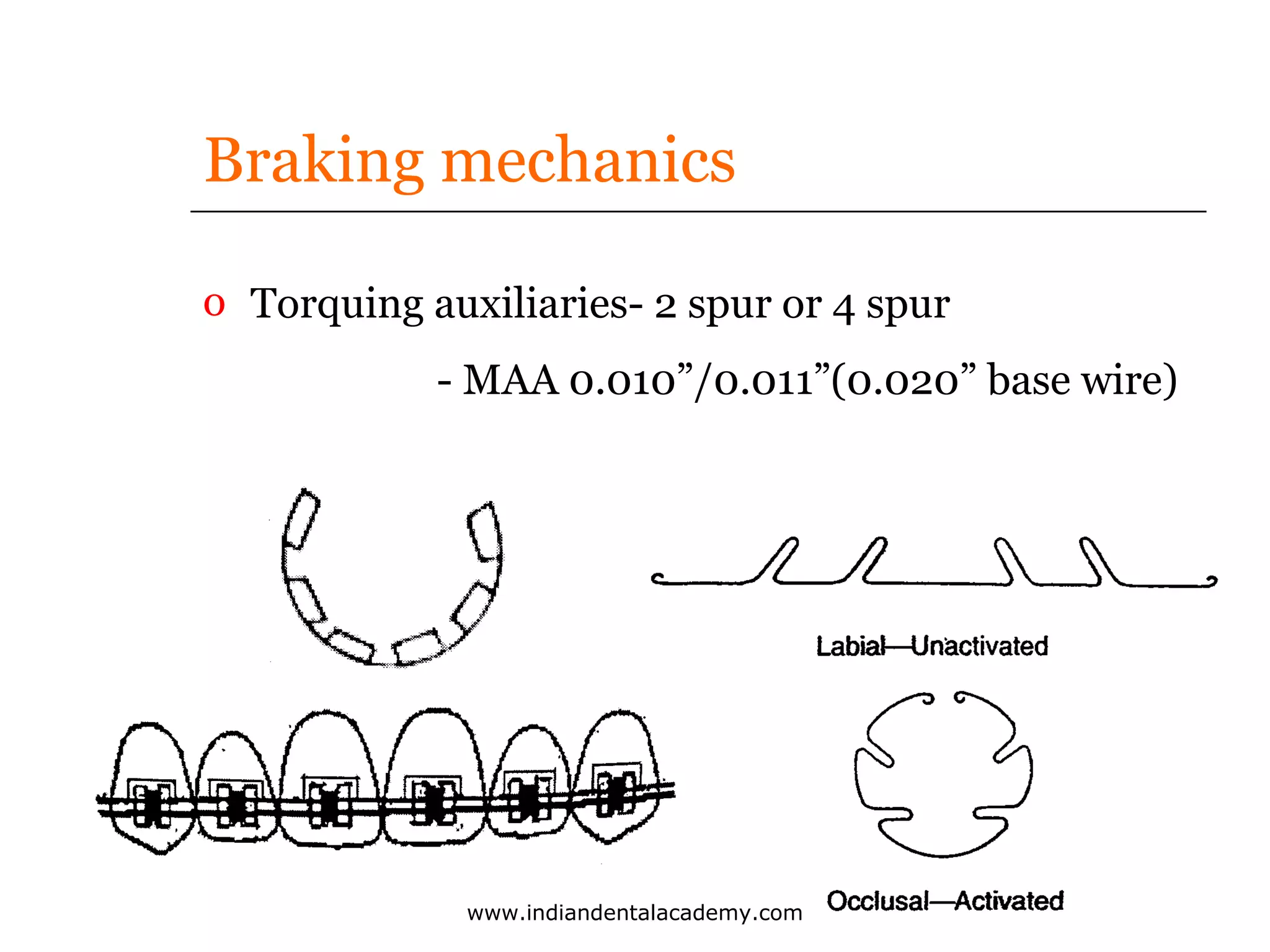
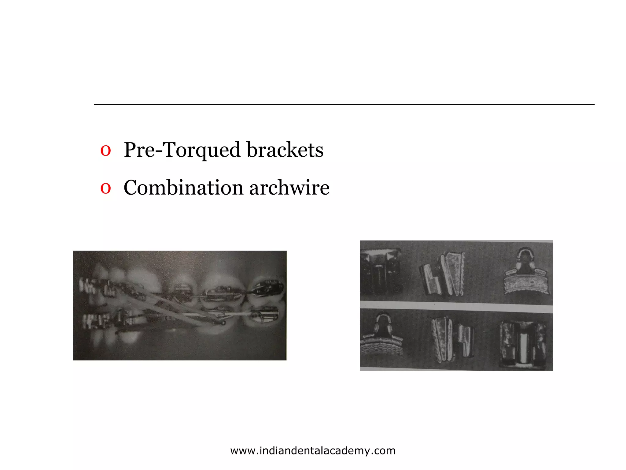
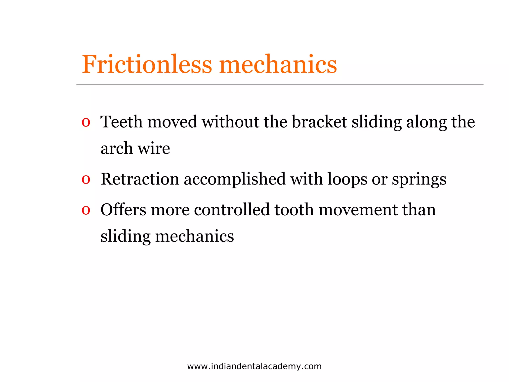
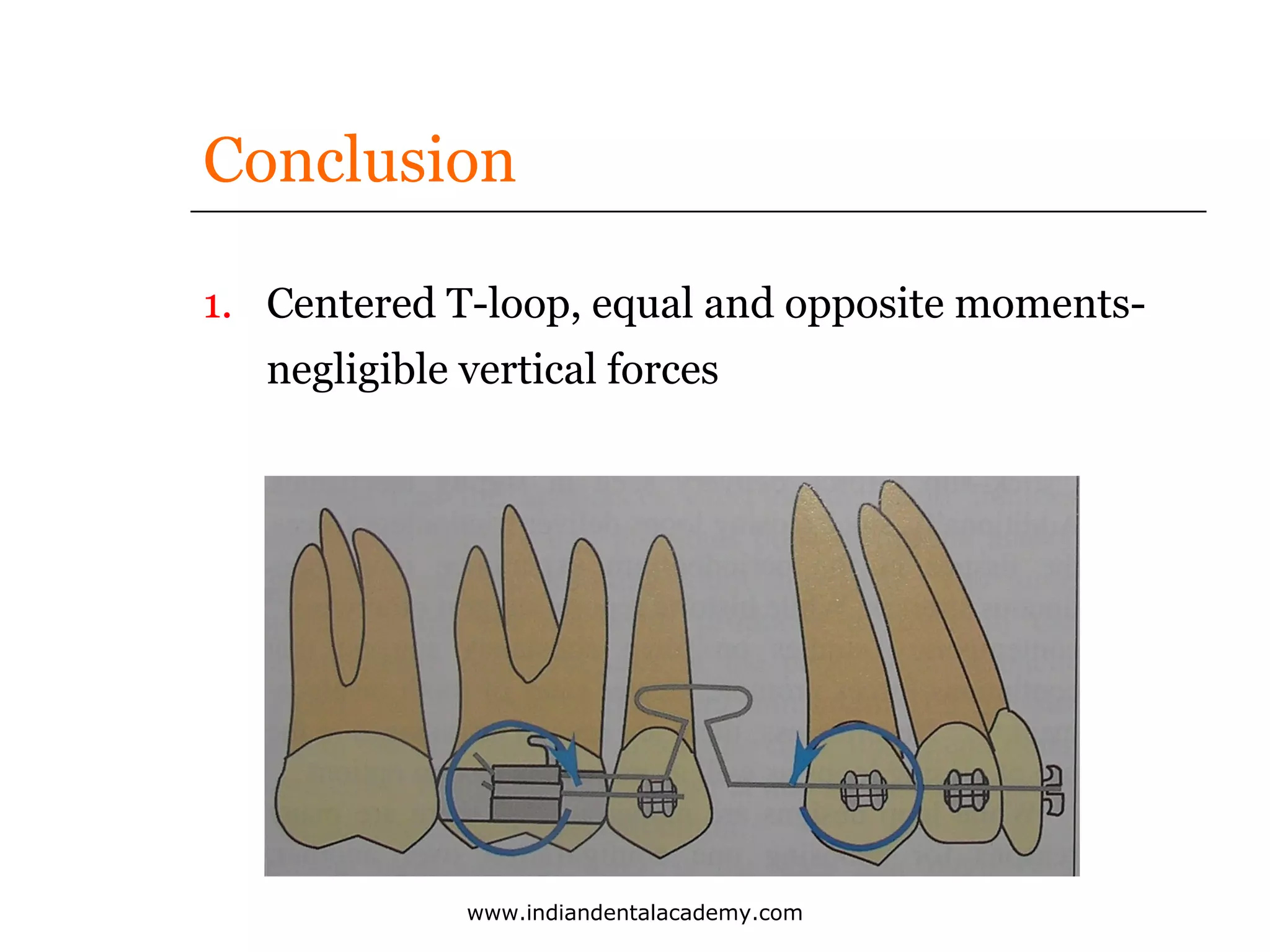
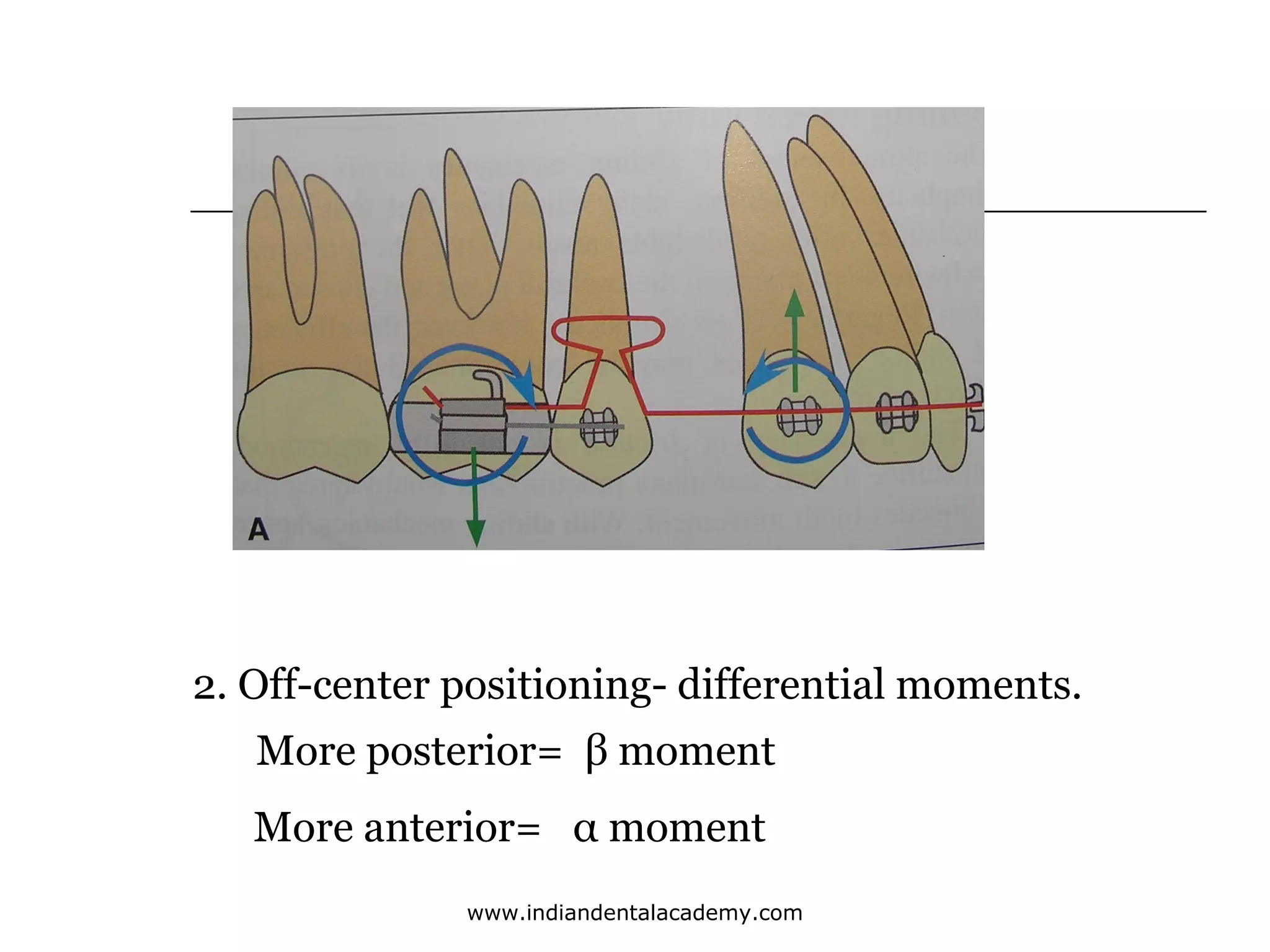
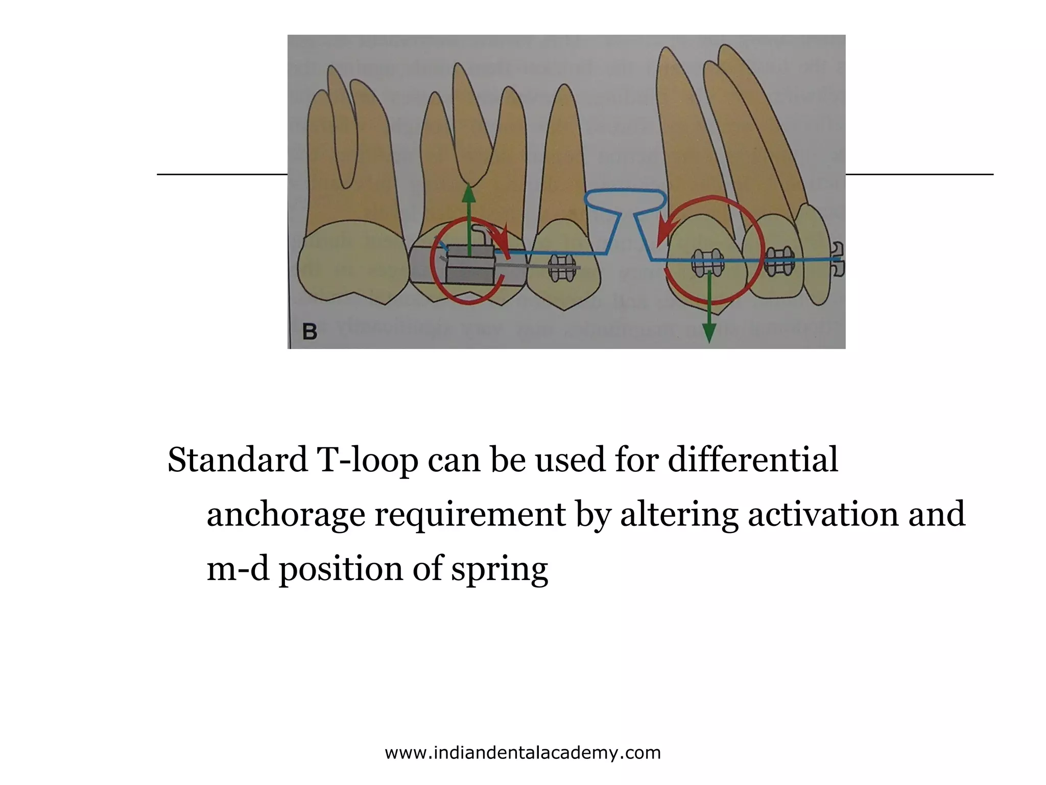
INDIAN DENTAL ACADEMY
Leader in continuing dental education
www.indiandentalacademy.com

2
www.indiandentalacademy.com
Ongoing Innovations in Biomechanics &
Materials for the New Millennium- Robert P. Kusy

www.indiandentalacademy.com
Conventional Begg
o Attritional occlusion in Australian
Aborigines
o Concept of differential forces

www.indiandentalacademy.com
Space closure in Begg
Stage II-

Objectives :
1. To maintain all corrections achieved
during stage I
2. To close all extraction spaces


Controlled tipping of incisors



Preventing excess tipping
www.indiandentalacademy.com
Space closure in Begg
Stage II- Archwires

o - 0.018” P/P+, 0.020” P
o Anchor bands reduced- maintain correction
o Maintain rotation, deepbite correction,
archform
o Resist rotational tendency of molars- class I
elastics
o No sliding of brackets- no slow down
www.indiandentalacademy.com
Controlled tipping of incisors
o MAA- lingual root torque- root control from the
beginning. 0.009”
o Uprighting spring- canine
o Incisors upright or slightly retroclined

www.indiandentalacademy.com
Elastics
o Differential configuration
o U/L class I

www.indiandentalacademy.com
Elastics
o Class II with lower class I- molar relation not
corrected

www.indiandentalacademy.com
Elastics
o Z configuration (class II part time)

www.indiandentalacademy.com
Elastics
o Class II only- U/L anteriors do not retract at the
same rate

www.indiandentalacademy.com
Elastics
o Lower class I only (anteriors in crossbite)

www.indiandentalacademy.com
Braking mechanics
o For protracting the posteriors
1. Braking pins
2. Angulated T pins
3. Combination wires
4. Torquing auxiliaries

www.indiandentalacademy.com
Braking mechanics
o Braking pins- passive uprighting springs, 0.018” almost
fill the bracket channel

www.indiandentalacademy.com
Braking mechanics
o Angulated T pins- maintain tipping

www.indiandentalacademy.com
Combination wiresSS/Alpha- titanium
Anterior segment0.022” x 0.018”- ribbon mode
Posterior segment- 0.018” round
Greater torque in anterior segment
= more bite deepening effect

www.indiandentalacademy.com
Braking mechanics
o Torquing auxiliaries- 2 spur or 4 spur
- MAA 0.010”/0.011”(0.020” base wire)

www.indiandentalacademy.com
o Duration of stage II–
 2 stages together approximately 1 year-not
more than 1 year 3 months

www.indiandentalacademy.com
KB Technique
o Kamedanized Begg- Akira Kameda
o Modifications to Conventional Begg technique.
o Stage II- torquing and space closure
o Rectangular tube with round or ribbon archwirephilosophy of low friction

www.indiandentalacademy.com
o Pre-Torqued brackets
o Combination archwire

www.indiandentalacademy.com
KB Technique
o Round wire in round tube
- Anchor molars tend to roll in.
- Correcting lingually inclined anchor molarsdifficult.
- Directing forces- difficult
- Bite opening efficiency decreased

www.indiandentalacademy.com
KB Technique
o Rectangular tube with round or ribbon archwiro Pre-Torqued brackets
o Combination archwires Alpha titanium
100% humidity= titanium hydrite- harden in the
mouth

www.indiandentalacademy.com
KB Technique
o By-Pass Loop- 3 dimensional control of 2nd PM

www.indiandentalacademy.com
KB Technique
o Torquing and en masse tooth movement
o E-link or 0.010” sectional supreme
- maintain inter canine distance
o Ribbon archwire into buccal tubes
o Power pins- for hooking elastics
o E- links or power chain- control rotation of anchor
molar

www.indiandentalacademy.com
J- Hook Headgear- John Hickam
o Straight pull type
o High pull type- bodily movement, aid in bite
opening
o Variable pull

J-hook assembly
www.indiandentalacademy.com
J- Hook Headgear- John Hickam

www.indiandentalacademy.com
o Disadvantages
o Force application is intermittent
o Patient co-operation
o Trauma of the soft tissues from the J-hook

www.indiandentalacademy.com
Sliding mechanics
Advantages
o Minimal wire bending
o Less time consuming
o Enhances patient comfort
o No running out of space for activation

www.indiandentalacademy.com
Sliding mechanics
Disadvantage
o Lack of efficiency compared to frictionless
mechanics
o Uncontrolled tipping
o Deepening of overbite
o Loss of anchorage

www.indiandentalacademy.com
Space closure in Tip Edge
Tip-Edge vs Original Edgewise bracket
o Unique slot- permits free crown tipping
o Allows differential tooth movement
o Light forces, minimal archwire deflectiondiminished anchorage demand
o Increased horizontal & vertical control

www.indiandentalacademy.com
o Tip-Edge vs Ribbon Arch Bracket

www.indiandentalacademy.com
Dr. SAFEENA

www.indiandentalacademy.com
Frictionless mechanics
o Teeth moved without the bracket sliding along the
arch wire
o Retraction accomplished with loops or springs
o Offers more controlled tooth movement than
sliding mechanics

www.indiandentalacademy.com
o Continuous arch- nonbroken archwire formed
around the dental arch, connects one bracket or
tube with the bracket on an adjacent tooth
o Segmented arch- sections of continuous arch
which are joined or connected together to form a
semblance of a continuous archwire
o Sectional arch- contains portions of a continuous
archwire that are not joined in any way to form an
integral unit
www.indiandentalacademy.com
Rationale of Segmented arch
o Consolidation of teeth into units- 2 buccal segments
and one anterior segment.
o Buccal segments- TPA, lingual arch
o Each segment- multirooted tooth
o Intrasegmental mechanics- alignment by segmental
archwires
o Segments consolidated into complete arch
o Allows use of wires of varying cross-section of archwire
o Side effects of forces easily controlledprefabricated/precalibrated
o

www.indiandentalacademy.com
Loops used in frictionless mechanicsRetraction Loops (springs)
Ideal loop design
o Deliver relatively low, nearly constant forces
o Accommodate large activation
o Comfortable to the patient
o Easy to fabricate

www.indiandentalacademy.com
o Burstone and Koenig
Ideal characteristics for effective physiologic tooth
movement
1. High M/F ratio required for translatory
movement
2. Low LDR, to maintain optimum force levels over
a long range

www.indiandentalacademy.com
Components of force system
o Alpha moment: acting on anterior teeth
o Beta moment: acting on posterior teeth
o Horizontal forces: mesiodistal
o Vertical forces: intrusive-extrusive

www.indiandentalacademy.com
Vertical loop
o Dr. Robert Strang- originator, for retraction
mechanics
o 2types
1. When used for opening spaces- legs should be
separated 3/32”, ¼” in height
2. When used for closing spaces, legs are close
together and parallel

www.indiandentalacademy.com
Standard vertical loop
o Simplest loop
o Fabricated as independent devices/incorporated
into continuous archwire
o Used for alignment and space closure

www.indiandentalacademy.com
Vertical Loop
o Open Vertical Loop

o Closed vertical loop

www.indiandentalacademy.com
Modifications of Vertical loop
o Bull loop- Dr. Harry Bull (1951)
o Loop legs tightly abutting each other.
o Omega loop- As mentioned by Dr. Morris Stoner
resemblance with Greek letter ‘omega’
o Believed to distribute stresses more evenly
through the curvature, instead of concentrating
them at apex

www.indiandentalacademy.com
Height restricted by anatomy of oral cavity
www.indiandentalacademy.com
o Forces optimum for canine retraction 1-2 N
(1N=102gms)
o Force levels at activation of vertical loop 4.4N
o Force-deflection relationship linear
o At 0.5mm activation- force levels half of those at 1mm
o Small movement of teeth- large in force levels
o M/F below ideal for controlled tipping and translation
o Change in design geometry
www.indiandentalacademy.com
o Closed loop- greater range of activation than open
loop= additional wire and
o Bauschinger effect- range of activation is always
greater in the direction of the last bend

www.indiandentalacademy.com
Standard vertical loop
Disadvantages
o Very high forceso Force & M/F extremely sensitive to small changes
in activation
o Discomfort to patient
o Loss of anchorage & root control
o Dumping of teeth
o Small activations-Rapid force decay, intermittent
force delivery
www.indiandentalacademy.com
Use of vertical loops in retraction
systems- Faulkner et al. AJO 1991
Effect of Helix
o Single apical helix- force= M/F
o Lateral helices- moment
o Combination- M/F slightly above 2 & activation

www.indiandentalacademy.com
o Apical helix
www.indiandentalacademy.com
o Preactivation
www.indiandentalacademy.com
Preactivation
o Same force/deflection
o Shifted moment/deflection
o M/F greater at low activation
o Spring very sensitive to small errors in
manufacture and installation- difficult to use in
practice.

www.indiandentalacademy.com
o Preactivation and Helices
www.indiandentalacademy.com
o Larger activation without permanent deformation
o Preactivation allows application of larger
moments
o Resultant moment still not large enough to
produce translation

www.indiandentalacademy.com
o Increasing size of apical and lateral helices
www.indiandentalacademy.com
Clinical Implications

www.indiandentalacademy.com
Clinical Implications

www.indiandentalacademy.com
L-loop
o Boot loop- horizontal extension added
o Force system becomes asymmetric
o Direction in which ‘L’ is placed- smaller moment
or force alone
o Generates greatest moment differential between 2
teeth
o Length of horizontal = differential force

www.indiandentalacademy.com
T- loop
o Addition of wire apically at the loop= M/F, LDR
o Segmented T-loop- 0.017 x 0.025 TMA

www.indiandentalacademy.com
T- loop
D=L–A
2
D – length of anterior & posterior arm
L – Inter bracket distance
A - Activation

www.indiandentalacademy.com
o A – Passive
o B – Neutral position
o C – full insertion

www.indiandentalacademy.com
T- loop
o Passive

www.indiandentalacademy.com
o Group A- loop closer to canine. Gable bend added
nearer the molar, larger β moment, increases
posterior anchorage
o Group B- Loop midway between posterior and
anterior segment
o Group C- loop closer to posterior segment

www.indiandentalacademy.com
T-loop position and anchorage control
AJO 1997–Kuhlberg and Burstone
o Effect of off-center positioning on force systems
produced by segmented 0.017 x 0.025 TMA T-loop
o Spring tested in 7 positions, centered,
1,2 &3mm towards anterior attachment and
1,2 & 3mm towards posterior attachment
o Measured over 6mm of spring activation & 23mm IBD
o Spring tester apparatus- University of Connecticut
o Alpha and beta moments, horizontal and vertical
forces measured
www.indiandentalacademy.com
Conclusion
1. Centered T-loop, equal and opposite momentsnegligible vertical forces

www.indiandentalacademy.com
2. Off-center positioning- differential moments.
More posterior= β moment
More anterior= α moment
www.indiandentalacademy.com
Standard T-loop can be used for differential
anchorage requirement by altering activation and
m-d position of spring

www.indiandentalacademy.com
o Results consistent with the effect of V-bend
activation in archwires for obtaining differential
force.
o Even 1mm of eccentricity produced marked
difference in α & β moments
o Spring positioning can be readily used as an effective
means of obtaining differential moments
o With vertical force, positioning a loop off-center for
convenience may produce undesirable results
www.indiandentalacademy.com
o For off-centered position magnitude of α,β &
horizontal forces was dependent on both activation
and position
o Horizontal force increased with increase in
eccentric position by aprox. 6 to 8gm/mm
o Moments increased for the side closer to the T-loop
and decreased for the further side.
o Vertical forces increased with greater off-centering
www.indiandentalacademy.com
o Design features to optimize force system
1. Material used-TMA-excellent spring back, good
formability
2. Additional wire apically to activation & M/F
3. Loop centricity
4. Large IBD- allows for sufficient activation

www.indiandentalacademy.com
Clinical Implications

www.indiandentalacademy.com
Thank you
For more details please visit
www.indiandentalacademy.com

www.indiandentalacademy.com

Space closure 2 /certified fixed orthodontic courses by Indian dental academy

  • 1.
    INDIAN DENTAL ACADEMY Leaderin continuing dental education www.indiandentalacademy.com 2 www.indiandentalacademy.com
  • 2.
    Ongoing Innovations inBiomechanics & Materials for the New Millennium- Robert P. Kusy www.indiandentalacademy.com
  • 3.
    Conventional Begg o Attritionalocclusion in Australian Aborigines o Concept of differential forces www.indiandentalacademy.com
  • 4.
    Space closure inBegg Stage II- Objectives : 1. To maintain all corrections achieved during stage I 2. To close all extraction spaces  Controlled tipping of incisors  Preventing excess tipping www.indiandentalacademy.com
  • 5.
    Space closure inBegg Stage II- Archwires o - 0.018” P/P+, 0.020” P o Anchor bands reduced- maintain correction o Maintain rotation, deepbite correction, archform o Resist rotational tendency of molars- class I elastics o No sliding of brackets- no slow down www.indiandentalacademy.com
  • 6.
    Controlled tipping ofincisors o MAA- lingual root torque- root control from the beginning. 0.009” o Uprighting spring- canine o Incisors upright or slightly retroclined www.indiandentalacademy.com
  • 7.
  • 8.
    Elastics o Differential configuration oU/L class I www.indiandentalacademy.com
  • 9.
    Elastics o Class IIwith lower class I- molar relation not corrected www.indiandentalacademy.com
  • 10.
    Elastics o Z configuration(class II part time) www.indiandentalacademy.com
  • 11.
    Elastics o Class IIonly- U/L anteriors do not retract at the same rate www.indiandentalacademy.com
  • 12.
    Elastics o Lower classI only (anteriors in crossbite) www.indiandentalacademy.com
  • 13.
    Braking mechanics o Forprotracting the posteriors 1. Braking pins 2. Angulated T pins 3. Combination wires 4. Torquing auxiliaries www.indiandentalacademy.com
  • 14.
    Braking mechanics o Brakingpins- passive uprighting springs, 0.018” almost fill the bracket channel www.indiandentalacademy.com
  • 15.
    Braking mechanics o AngulatedT pins- maintain tipping www.indiandentalacademy.com
  • 16.
    Combination wiresSS/Alpha- titanium Anteriorsegment0.022” x 0.018”- ribbon mode Posterior segment- 0.018” round Greater torque in anterior segment = more bite deepening effect www.indiandentalacademy.com
  • 17.
    Braking mechanics o Torquingauxiliaries- 2 spur or 4 spur - MAA 0.010”/0.011”(0.020” base wire) www.indiandentalacademy.com
  • 18.
    o Duration ofstage II–  2 stages together approximately 1 year-not more than 1 year 3 months www.indiandentalacademy.com
  • 19.
    KB Technique o KamedanizedBegg- Akira Kameda o Modifications to Conventional Begg technique. o Stage II- torquing and space closure o Rectangular tube with round or ribbon archwirephilosophy of low friction www.indiandentalacademy.com
  • 20.
    o Pre-Torqued brackets oCombination archwire www.indiandentalacademy.com
  • 21.
    KB Technique o Roundwire in round tube - Anchor molars tend to roll in. - Correcting lingually inclined anchor molarsdifficult. - Directing forces- difficult - Bite opening efficiency decreased www.indiandentalacademy.com
  • 22.
    KB Technique o Rectangulartube with round or ribbon archwiro Pre-Torqued brackets o Combination archwires Alpha titanium 100% humidity= titanium hydrite- harden in the mouth www.indiandentalacademy.com
  • 23.
    KB Technique o By-PassLoop- 3 dimensional control of 2nd PM www.indiandentalacademy.com
  • 24.
    KB Technique o Torquingand en masse tooth movement o E-link or 0.010” sectional supreme - maintain inter canine distance o Ribbon archwire into buccal tubes o Power pins- for hooking elastics o E- links or power chain- control rotation of anchor molar www.indiandentalacademy.com
  • 25.
  • 26.
  • 27.
  • 28.
    J- Hook Headgear-John Hickam o Straight pull type o High pull type- bodily movement, aid in bite opening o Variable pull J-hook assembly www.indiandentalacademy.com
  • 29.
    J- Hook Headgear-John Hickam www.indiandentalacademy.com
  • 30.
    o Disadvantages o Forceapplication is intermittent o Patient co-operation o Trauma of the soft tissues from the J-hook www.indiandentalacademy.com
  • 31.
    Sliding mechanics Advantages o Minimalwire bending o Less time consuming o Enhances patient comfort o No running out of space for activation www.indiandentalacademy.com
  • 32.
    Sliding mechanics Disadvantage o Lackof efficiency compared to frictionless mechanics o Uncontrolled tipping o Deepening of overbite o Loss of anchorage www.indiandentalacademy.com
  • 33.
    Space closure inTip Edge Tip-Edge vs Original Edgewise bracket o Unique slot- permits free crown tipping o Allows differential tooth movement o Light forces, minimal archwire deflectiondiminished anchorage demand o Increased horizontal & vertical control www.indiandentalacademy.com
  • 34.
    o Tip-Edge vsRibbon Arch Bracket www.indiandentalacademy.com
  • 35.
  • 36.
  • 37.
  • 38.
  • 39.
    Frictionless mechanics o Teethmoved without the bracket sliding along the arch wire o Retraction accomplished with loops or springs o Offers more controlled tooth movement than sliding mechanics www.indiandentalacademy.com
  • 40.
    o Continuous arch-nonbroken archwire formed around the dental arch, connects one bracket or tube with the bracket on an adjacent tooth o Segmented arch- sections of continuous arch which are joined or connected together to form a semblance of a continuous archwire o Sectional arch- contains portions of a continuous archwire that are not joined in any way to form an integral unit www.indiandentalacademy.com
  • 41.
    Rationale of Segmentedarch o Consolidation of teeth into units- 2 buccal segments and one anterior segment. o Buccal segments- TPA, lingual arch o Each segment- multirooted tooth o Intrasegmental mechanics- alignment by segmental archwires o Segments consolidated into complete arch o Allows use of wires of varying cross-section of archwire o Side effects of forces easily controlledprefabricated/precalibrated o www.indiandentalacademy.com
  • 42.
    Loops used infrictionless mechanicsRetraction Loops (springs) Ideal loop design o Deliver relatively low, nearly constant forces o Accommodate large activation o Comfortable to the patient o Easy to fabricate www.indiandentalacademy.com
  • 43.
    o Burstone andKoenig Ideal characteristics for effective physiologic tooth movement 1. High M/F ratio required for translatory movement 2. Low LDR, to maintain optimum force levels over a long range www.indiandentalacademy.com
  • 44.
    Components of forcesystem o Alpha moment: acting on anterior teeth o Beta moment: acting on posterior teeth o Horizontal forces: mesiodistal o Vertical forces: intrusive-extrusive www.indiandentalacademy.com
  • 45.
    Vertical loop o Dr.Robert Strang- originator, for retraction mechanics o 2types 1. When used for opening spaces- legs should be separated 3/32”, ¼” in height 2. When used for closing spaces, legs are close together and parallel www.indiandentalacademy.com
  • 46.
  • 47.
    Standard vertical loop oSimplest loop o Fabricated as independent devices/incorporated into continuous archwire o Used for alignment and space closure www.indiandentalacademy.com
  • 48.
    Vertical Loop o OpenVertical Loop o Closed vertical loop www.indiandentalacademy.com
  • 49.
    Modifications of Verticalloop o Bull loop- Dr. Harry Bull (1951) o Loop legs tightly abutting each other. o Omega loop- As mentioned by Dr. Morris Stoner resemblance with Greek letter ‘omega’ o Believed to distribute stresses more evenly through the curvature, instead of concentrating them at apex www.indiandentalacademy.com
  • 50.
    Height restricted byanatomy of oral cavity www.indiandentalacademy.com
  • 51.
  • 52.
    o Forces optimumfor canine retraction 1-2 N (1N=102gms) o Force levels at activation of vertical loop 4.4N o Force-deflection relationship linear o At 0.5mm activation- force levels half of those at 1mm o Small movement of teeth- large in force levels o M/F below ideal for controlled tipping and translation o Change in design geometry www.indiandentalacademy.com
  • 53.
    o Closed loop-greater range of activation than open loop= additional wire and o Bauschinger effect- range of activation is always greater in the direction of the last bend www.indiandentalacademy.com
  • 54.
    Standard vertical loop Disadvantages oVery high forceso Force & M/F extremely sensitive to small changes in activation o Discomfort to patient o Loss of anchorage & root control o Dumping of teeth o Small activations-Rapid force decay, intermittent force delivery www.indiandentalacademy.com
  • 55.
    Use of verticalloops in retraction systems- Faulkner et al. AJO 1991 Effect of Helix o Single apical helix- force= M/F o Lateral helices- moment o Combination- M/F slightly above 2 & activation www.indiandentalacademy.com
  • 56.
  • 57.
  • 58.
    Preactivation o Same force/deflection oShifted moment/deflection o M/F greater at low activation o Spring very sensitive to small errors in manufacture and installation- difficult to use in practice. www.indiandentalacademy.com
  • 59.
    o Preactivation andHelices www.indiandentalacademy.com
  • 60.
    o Larger activationwithout permanent deformation o Preactivation allows application of larger moments o Resultant moment still not large enough to produce translation www.indiandentalacademy.com
  • 61.
    o Increasing sizeof apical and lateral helices www.indiandentalacademy.com
  • 62.
  • 63.
  • 64.
    L-loop o Boot loop-horizontal extension added o Force system becomes asymmetric o Direction in which ‘L’ is placed- smaller moment or force alone o Generates greatest moment differential between 2 teeth o Length of horizontal = differential force www.indiandentalacademy.com
  • 65.
    T- loop o Additionof wire apically at the loop= M/F, LDR o Segmented T-loop- 0.017 x 0.025 TMA www.indiandentalacademy.com
  • 66.
    T- loop D=L–A 2 D –length of anterior & posterior arm L – Inter bracket distance A - Activation www.indiandentalacademy.com
  • 67.
    o A –Passive o B – Neutral position o C – full insertion www.indiandentalacademy.com
  • 68.
  • 69.
  • 70.
    o Group A-loop closer to canine. Gable bend added nearer the molar, larger β moment, increases posterior anchorage o Group B- Loop midway between posterior and anterior segment o Group C- loop closer to posterior segment www.indiandentalacademy.com
  • 71.
    T-loop position andanchorage control AJO 1997–Kuhlberg and Burstone o Effect of off-center positioning on force systems produced by segmented 0.017 x 0.025 TMA T-loop o Spring tested in 7 positions, centered, 1,2 &3mm towards anterior attachment and 1,2 & 3mm towards posterior attachment o Measured over 6mm of spring activation & 23mm IBD o Spring tester apparatus- University of Connecticut o Alpha and beta moments, horizontal and vertical forces measured www.indiandentalacademy.com
  • 72.
    Conclusion 1. Centered T-loop,equal and opposite momentsnegligible vertical forces www.indiandentalacademy.com
  • 73.
    2. Off-center positioning-differential moments. More posterior= β moment More anterior= α moment www.indiandentalacademy.com
  • 74.
    Standard T-loop canbe used for differential anchorage requirement by altering activation and m-d position of spring www.indiandentalacademy.com
  • 75.
    o Results consistentwith the effect of V-bend activation in archwires for obtaining differential force. o Even 1mm of eccentricity produced marked difference in α & β moments o Spring positioning can be readily used as an effective means of obtaining differential moments o With vertical force, positioning a loop off-center for convenience may produce undesirable results www.indiandentalacademy.com
  • 76.
    o For off-centeredposition magnitude of α,β & horizontal forces was dependent on both activation and position o Horizontal force increased with increase in eccentric position by aprox. 6 to 8gm/mm o Moments increased for the side closer to the T-loop and decreased for the further side. o Vertical forces increased with greater off-centering www.indiandentalacademy.com
  • 77.
    o Design featuresto optimize force system 1. Material used-TMA-excellent spring back, good formability 2. Additional wire apically to activation & M/F 3. Loop centricity 4. Large IBD- allows for sufficient activation www.indiandentalacademy.com
  • 78.
  • 79.
    Thank you For moredetails please visit www.indiandentalacademy.com www.indiandentalacademy.com