This chapter discusses how to build a geodatabase, including creating one from an existing design or from scratch. It describes how geodatabases work with ArcCatalog and ArcMap. The first step in building a geodatabase is to create the database. Other topics covered include copying the schema from another geodatabase and tips for learning to build and edit geodatabases.


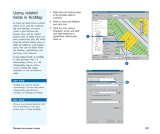
![20 BUILDING A GEODATABASE
Geodatabases organize geographic data into a hierarchy of data
objects. These data objects are stored in feature classes, object
classes, and feature datasets. An object class is a table in the
geodatabase that stores nonspatial data. A feature class is a
collection of features with the same type of geometry and the
same attributes.
A feature dataset is a collection of feature classes that share the
same spatial reference. Feature classes that store simple features
can be organized either inside or outside a feature dataset. Simple
feature classes that are outside a feature dataset are called
standalone feature classes. Feature classes that store topological
features must be contained within a feature dataset to ensure a
common spatial reference.
ArcCatalog contains tools for creating object classes (tables),
feature classes, and feature datasets. Once these items are
created in the geodatabase, further items such as subtypes,
relationship classes, geometric networks, and topologies can also
be created. These geodatabase items are covered in subsequent
chapters.
Spatial reference
When creating a new feature dataset or standalone feature class,
you must specify its spatial reference. The spatial reference for a
feature class describes its coordinate system (for example,
geographic, Universal Transverse Mercator [UTM], and State
Plane), spatial domain, and precision. The spatial domain is best
described as the allowable coordinate range for x,y coordinates,
m (measure) values, and z-values. The precision describes the
number of system units per one unit of measure. A spatial
reference with a precision of 1 will store integer values, while a
precision of 1,000 will store three decimal places. Once the spatial
reference for a feature dataset or standalone feature class has
been set, only the coordinate system can be modified—the
spatial domain is fixed.
All feature classes in a feature dataset share the same spatial
reference. The spatial reference is an important part of
geodatabase design because its spatial domain describes the
maximum spatial extent to which the data can grow. You must be
careful to choose an appropriate x, y, m, and z domain. For
example, if you create a feature dataset with a minimum z-value of
0 and a precision of 1,000, none of the features in the feature
dataset can have z-values that are less than 0, and all z-values will
be stored to three decimal places. The same rule applies to x- and
y-values. The exception to the rule is m domains; feature classes
within the same feature dataset can have different m domains.
The spatial domain for a feature class or feature dataset cannot be
changed. If the required x-, y-, m-, or z-value ranges for your
database change, the data has to be reloaded into feature classes
with a spatial reference that accommodates the new value range.
A collection of predefined geographic and projected coordinate
systems is installed with ArcInfo. You can create custom
coordinate systems, or you can import a coordinate system from
an existing feature class, feature dataset, coverage, or shapefile.
You can read more about spatial references and spatial domains in
Managing ArcSDE Services and Understanding Map
Projections.
Spatial index grid
Much like you use a locator grid on a city map to find a street,
ArcMap uses grids to quickly locate features in feature classes.
Identifying a feature, selecting features by pointing or dragging a
box, and panning and zooming all require ArcMap to use the
spatial index grid to locate features.
A feature class can have up to three grids. The size of each must
be at least three times the previous grid size. For most feature
classes, only a single grid size is required. Feature classes with
features of very different sizes may require additional grids so
that larger features can be queried faster.
Geodatabase items](https://image.slidesharecdn.com/buildingageodatabasearcgis9-221009172428-34b6e54c/85/Building_a_Geodatabase_ArcGIS_9-pdf-28-320.jpg)


![34 BUILDING A GEODATABASE
Min X = ([DataMinX + DataMaxX] / 2) - Domain
center in coordinate system units
Min Y = ([DataMinY + DataMaxY] / 2) - Domain
center in coordinate system units
This equation finds the minimum coordinates of your spatial
domain to locate the center of your data at the center of the
domain. Remember, all these calculations are in coordinate system
units. Examine this equation for the x dimension given the
example data:
First, find the center of your data.
(DataMinX + DataMaxX) ÷ 2
(200,000 + 1,000,000) ÷ 2 = 600,000
Next, find the difference between the center of your data and the
center of the geodatabase space.
Min X = 600,000 – 1,073,741.824 = -473,741.824
Because this is a negative number, the spatial domain will shift to
the left. Remember, the shift is applied to the spatial domain, not
the data. The shift is calculated for both dimensions, so you
would need to repeat this process for the y coordinates.
Using your calculated spatial domain in
ArcCatalog
Once you have calculated an appropriate spatial domain, you are
ready to create spatial data in the geodatabase. When creating
your first dataset, navigate to the X/Y Domain tab of the spatial
reference properties and enter the Min X, Min Y, and precision
values that you calculated. The maximum x and y values will be
calculated automatically. For all subsequent data that you import
or create, you can simply import this spatial reference. You can
also set your geoprocessing environment so that all new data
created from geoprocessing operations uses this spatial
reference. See Approach A for how to set the geoprocessing
environment to use a spatial reference from a feature class.
Defining Z and M spatial domains
The z and m domains are easier to calculate than the x and y
domains. Examine your data and enter the lowest value for the
minimum value and the precision to support its accuracy. You can
calculate z and m precision the same way you calculated precision
for the x and y coordinates. Just like x and y coordinates, you
have 2,147,483,648 storage units to work with. Generally it is not
necessary to center the z and m domains about the data as you
can set an absolute minimum based on your data.
When calculating the minimum for a z domain, you could use the
lowest point on the earth (-11,033 meters, located at the Mariana
Trench off the coast of Japan). Generally m coordinates are
positive numbers, so a minimum value of 0 may be appropriate.
You may also set the minimum m to have a slight negative offset
to account for negative values that could be produced by the
extrapolation of measures during operations like Calibrate. These
negative values could be corrected later instead of rejected
during the extrapolation.](https://image.slidesharecdn.com/buildingageodatabasearcgis9-221009172428-34b6e54c/85/Building_a_Geodatabase_ArcGIS_9-pdf-42-320.jpg)