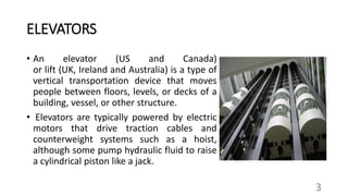
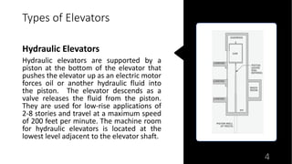
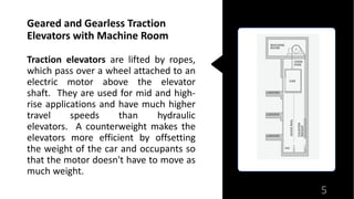
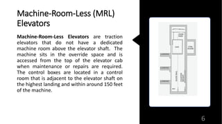
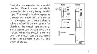
Building Elevators
1
By
-Uday Aware
Topic to be covered-
• Introduction
• Types of Elevators
• Working Principle
• Lift Specification
• Motor Specification
2
ELEVATORS
• An elevator (US and Canada)
or lift (UK, Ireland and Australia) is a type of
vertical transportation device that moves
people between floors, levels, or decks of a
building, vessel, or other structure.
• Elevators are typically powered by electric
motors that drive traction cables and
counterweight systems such as a hoist,
although some pump hydraulic fluid to raise
a cylindrical piston like a jack.
3
Types of Elevators
Hydraulic Elevators
Hydraulic elevators are supported by a
piston at the bottom of the elevator that
pushes the elevator up as an electric motor
forces oil or another hydraulic fluid into
the piston. The elevator descends as a
valve releases the fluid from the piston.
They are used for low-rise applications of
2-8 stories and travel at a maximum speed
of 200 feet per minute. The machine room
for hydraulic elevators is located at the
lowest level adjacent to the elevator shaft.
4
Geared and Gearless Traction
Elevators with Machine Room
Traction elevators are lifted by ropes,
which pass over a wheel attached to an
electric motor above the elevator
shaft. They are used for mid and high-
rise applications and have much higher
travel speeds than hydraulic
elevators. A counterweight makes the
elevators more efficient by offsetting
the weight of the car and occupants so
that the motor doesn't have to move as
much weight.
5
Machine-Room-Less (MRL)
Elevators
Machine-Room-Less Elevators are traction
elevators that do not have a dedicated
machine room above the elevator shaft. The
machine sits in the override space and is
accessed from the top of the elevator cab
when maintenance or repairs are required.
The control boxes are located in a control
room that is adjacent to the elevator shaft on
the highest landing and within around 150 feet
of the machine.
6
Working Principle
The working principle of an elevator or lift is similar to the pulley
system. A pulley system is used to draw the water from the well.
This pulley system can be designed with a bucket, a rope with a wheel.
A bucket is connected to a rope that passes throughout a wheel. This
can make it very easy to draw the water from the well. Similarly,
present elevators use the same concept. But the main difference
between these two are; pulley systems are operated manually
whereas an elevator uses sophisticated mechanisms for handling the
elevator’s load
7
Basically, an elevator is a metal
box in different shapes which is
connected to a very tough metal
rope. The tough metal rope passes
through a sheave on the elevator
in the engine room. Here a sheave
is like a wheel in pulley system for
clutching the metal rope strongly.
This system can be operated by a
motor. When the switch is turned
ON, the motor can be activated
when the elevator goes up and
down or stops.
8
• Warm gear are gear which are widely used for transmitting
power at high velo ratios between non intersecting shaft
that are generally, but not necessarily , at right angle
• It can give velocity ratio as 300:1vor more.
• It is mostly used as a speed reducer ,which consist of worm
and worm wheel or gear
• The worm wheel or gear is similar to a helical gear with a
face curved to conform to shape of worm
Worm Gear
Worm Gear Box
The Involute Worm Gearboxes/Reduction Gear Units are
worm type units with modular construction. The units
comprise of hardened ground worms with centrifugally
cast bronze gears.
Specification :
 Worm gear boxes range from Center Distance of 25 mm
to 150 mm
 Ratios up to 70:1 or customized as per requirements
 One or two output shafts
 Foot or flange mounted with hollow input shafts for
standard IEC motor
Advantages
1. Worm gear drives operate silently and smoothly.
2. They are self locking
3. They occupy less space
4. They have good meshing effectiveness.
5. They can be used for reducing speed and increasing torque.
6. High velo ratio of the order of 100 can be obtained in single step
Disadvantage
1. Worm gear material are expansive
2. Worm drives have high power losses and low transmission
efficiency
3. They produces a lot of heat
Lift Specifications
• Supplying, Erecting and putting into commission One Fully Automatic V3F Power
server Microprocessor Selective/Down Collective passenger lift having following
specifications-
• Type of lift-Passenger lift.
• Capacity/Person-408 kgs/6 persons
• Number of Floors-4 Landings(ground plus 3 upper floors)
• Travel Height-50-60 feet.
• Speed of Lift-0.65MPS.
• Type of Controller-Fully Automatic Down.
• Collective Micro-proccessor Controller having 3.75 KVA L&T make Drive.
13
• Emergency Rescue : Battery operated Emergency Rescue
Device(ERD) to bring the lift to nearest landing in case of
power failure.
• Landing Doors : All the landing entrances will be protected by
M.S Imperforated Door.
• Car Door : Entrance will be protected by M.S Imperforated
Door.
• Lift Car : The lift car will have S.S.304 grade. 1.2mm thickness
Mirror and matt sheet panel combination for side panels and
the false ceiling will be of S.S mirror sheet having LED Bulbs.
• Car Push Button : The car finish button will have steel finish
illuminated switches for all floors, Electronic Floor Position
indicator, up down arrow indication
14
An induction motor or asynchronous motor is an AC electric motor in
which the electric current in the rotor needed to produce torque is
obtained by electromagnetic induction from the magnetic field of
the stator winding.
In both induction and synchronous motors, the AC power supplied
to the motor's stator creates a magnetic field that rotates in synchronism
with the AC oscillations. Whereas a synchronous motor's rotor turns at
the same rate as the stator field, an induction motor's rotor rotates at a
somewhat slower speed than the stator field. The induction motor
stator's magnetic field is therefore changing or rotating relative to the
rotor.
Three phase Induction Motor :
15
Due to Lenz's Law, the direction of the
magnetic field created will be such as to
oppose the change in current through the
rotor windings. The cause of induced
current in the rotor windings is the rotating
stator magnetic field, so to oppose the
change in rotor-winding currents the rotor
will start to rotate in the direction of the
rotating stator magnetic field. The rotor
accelerates until the magnitude of induced
rotor current and torque balances the
applied mechanical load on the rotation of
the rotor.
16
Manufacture : Montanari Lift Components Pvt.Ltd.
Type : Three Phase Induction Motor (M76)
RPM : 1381 Power : 300-415 V
Power : 4KW Type of Drive : A.C. Generated Motor
Weight : 64 KG Gear Ratio : 60/1
17
Thank You
18

Building Elevators

  • 1.
  • 2.
    Topic to becovered- • Introduction • Types of Elevators • Working Principle • Lift Specification • Motor Specification 2
  • 3.
    ELEVATORS • An elevator(US and Canada) or lift (UK, Ireland and Australia) is a type of vertical transportation device that moves people between floors, levels, or decks of a building, vessel, or other structure. • Elevators are typically powered by electric motors that drive traction cables and counterweight systems such as a hoist, although some pump hydraulic fluid to raise a cylindrical piston like a jack. 3
  • 4.
    Types of Elevators HydraulicElevators Hydraulic elevators are supported by a piston at the bottom of the elevator that pushes the elevator up as an electric motor forces oil or another hydraulic fluid into the piston. The elevator descends as a valve releases the fluid from the piston. They are used for low-rise applications of 2-8 stories and travel at a maximum speed of 200 feet per minute. The machine room for hydraulic elevators is located at the lowest level adjacent to the elevator shaft. 4
  • 5.
    Geared and GearlessTraction Elevators with Machine Room Traction elevators are lifted by ropes, which pass over a wheel attached to an electric motor above the elevator shaft. They are used for mid and high- rise applications and have much higher travel speeds than hydraulic elevators. A counterweight makes the elevators more efficient by offsetting the weight of the car and occupants so that the motor doesn't have to move as much weight. 5
  • 6.
    Machine-Room-Less (MRL) Elevators Machine-Room-Less Elevatorsare traction elevators that do not have a dedicated machine room above the elevator shaft. The machine sits in the override space and is accessed from the top of the elevator cab when maintenance or repairs are required. The control boxes are located in a control room that is adjacent to the elevator shaft on the highest landing and within around 150 feet of the machine. 6
  • 7.
    Working Principle The workingprinciple of an elevator or lift is similar to the pulley system. A pulley system is used to draw the water from the well. This pulley system can be designed with a bucket, a rope with a wheel. A bucket is connected to a rope that passes throughout a wheel. This can make it very easy to draw the water from the well. Similarly, present elevators use the same concept. But the main difference between these two are; pulley systems are operated manually whereas an elevator uses sophisticated mechanisms for handling the elevator’s load 7
  • 8.
    Basically, an elevatoris a metal box in different shapes which is connected to a very tough metal rope. The tough metal rope passes through a sheave on the elevator in the engine room. Here a sheave is like a wheel in pulley system for clutching the metal rope strongly. This system can be operated by a motor. When the switch is turned ON, the motor can be activated when the elevator goes up and down or stops. 8
  • 9.
    • Warm gearare gear which are widely used for transmitting power at high velo ratios between non intersecting shaft that are generally, but not necessarily , at right angle • It can give velocity ratio as 300:1vor more. • It is mostly used as a speed reducer ,which consist of worm and worm wheel or gear • The worm wheel or gear is similar to a helical gear with a face curved to conform to shape of worm Worm Gear
  • 10.
    Worm Gear Box TheInvolute Worm Gearboxes/Reduction Gear Units are worm type units with modular construction. The units comprise of hardened ground worms with centrifugally cast bronze gears. Specification :  Worm gear boxes range from Center Distance of 25 mm to 150 mm  Ratios up to 70:1 or customized as per requirements  One or two output shafts  Foot or flange mounted with hollow input shafts for standard IEC motor
  • 11.
    Advantages 1. Worm geardrives operate silently and smoothly. 2. They are self locking 3. They occupy less space 4. They have good meshing effectiveness. 5. They can be used for reducing speed and increasing torque. 6. High velo ratio of the order of 100 can be obtained in single step
  • 12.
    Disadvantage 1. Worm gearmaterial are expansive 2. Worm drives have high power losses and low transmission efficiency 3. They produces a lot of heat
  • 13.
    Lift Specifications • Supplying,Erecting and putting into commission One Fully Automatic V3F Power server Microprocessor Selective/Down Collective passenger lift having following specifications- • Type of lift-Passenger lift. • Capacity/Person-408 kgs/6 persons • Number of Floors-4 Landings(ground plus 3 upper floors) • Travel Height-50-60 feet. • Speed of Lift-0.65MPS. • Type of Controller-Fully Automatic Down. • Collective Micro-proccessor Controller having 3.75 KVA L&T make Drive. 13
  • 14.
    • Emergency Rescue: Battery operated Emergency Rescue Device(ERD) to bring the lift to nearest landing in case of power failure. • Landing Doors : All the landing entrances will be protected by M.S Imperforated Door. • Car Door : Entrance will be protected by M.S Imperforated Door. • Lift Car : The lift car will have S.S.304 grade. 1.2mm thickness Mirror and matt sheet panel combination for side panels and the false ceiling will be of S.S mirror sheet having LED Bulbs. • Car Push Button : The car finish button will have steel finish illuminated switches for all floors, Electronic Floor Position indicator, up down arrow indication 14
  • 15.
    An induction motoror asynchronous motor is an AC electric motor in which the electric current in the rotor needed to produce torque is obtained by electromagnetic induction from the magnetic field of the stator winding. In both induction and synchronous motors, the AC power supplied to the motor's stator creates a magnetic field that rotates in synchronism with the AC oscillations. Whereas a synchronous motor's rotor turns at the same rate as the stator field, an induction motor's rotor rotates at a somewhat slower speed than the stator field. The induction motor stator's magnetic field is therefore changing or rotating relative to the rotor. Three phase Induction Motor : 15
  • 16.
    Due to Lenz'sLaw, the direction of the magnetic field created will be such as to oppose the change in current through the rotor windings. The cause of induced current in the rotor windings is the rotating stator magnetic field, so to oppose the change in rotor-winding currents the rotor will start to rotate in the direction of the rotating stator magnetic field. The rotor accelerates until the magnitude of induced rotor current and torque balances the applied mechanical load on the rotation of the rotor. 16
  • 17.
    Manufacture : MontanariLift Components Pvt.Ltd. Type : Three Phase Induction Motor (M76) RPM : 1381 Power : 300-415 V Power : 4KW Type of Drive : A.C. Generated Motor Weight : 64 KG Gear Ratio : 60/1 17
  • 18.