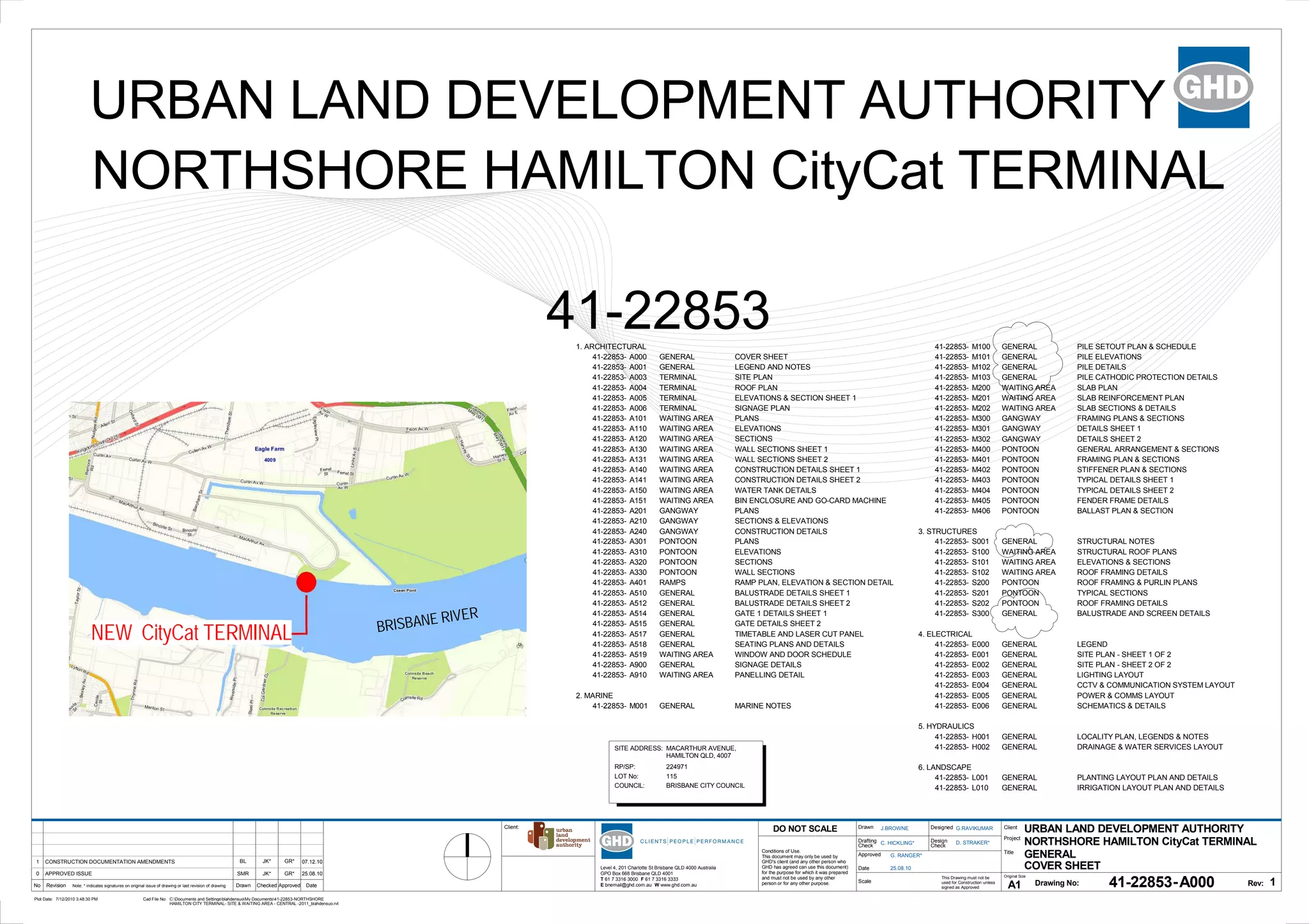
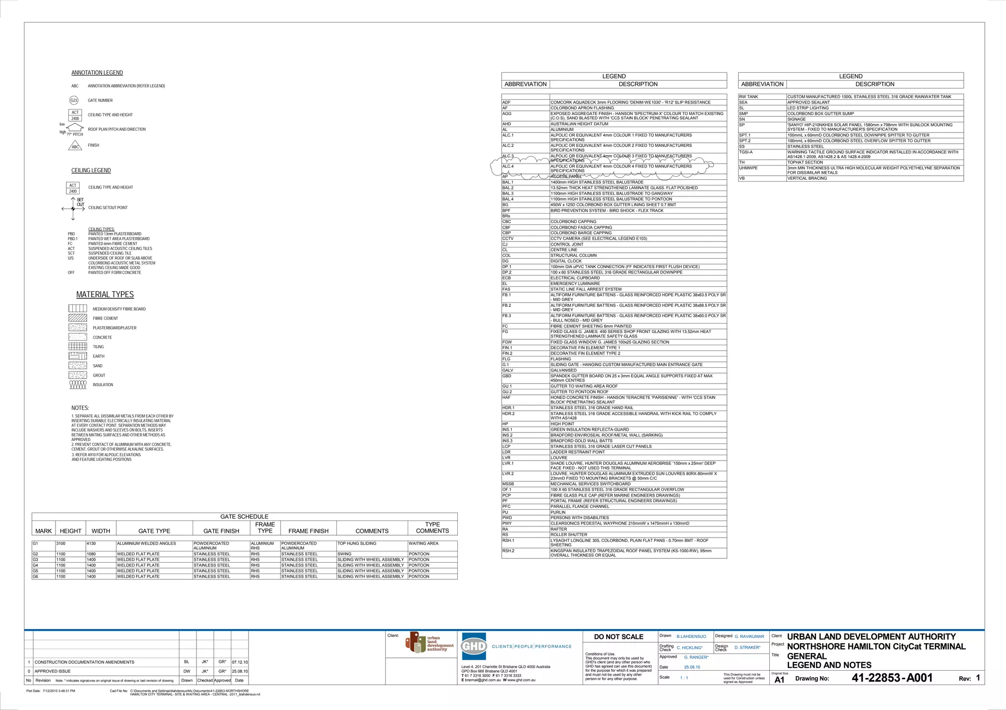
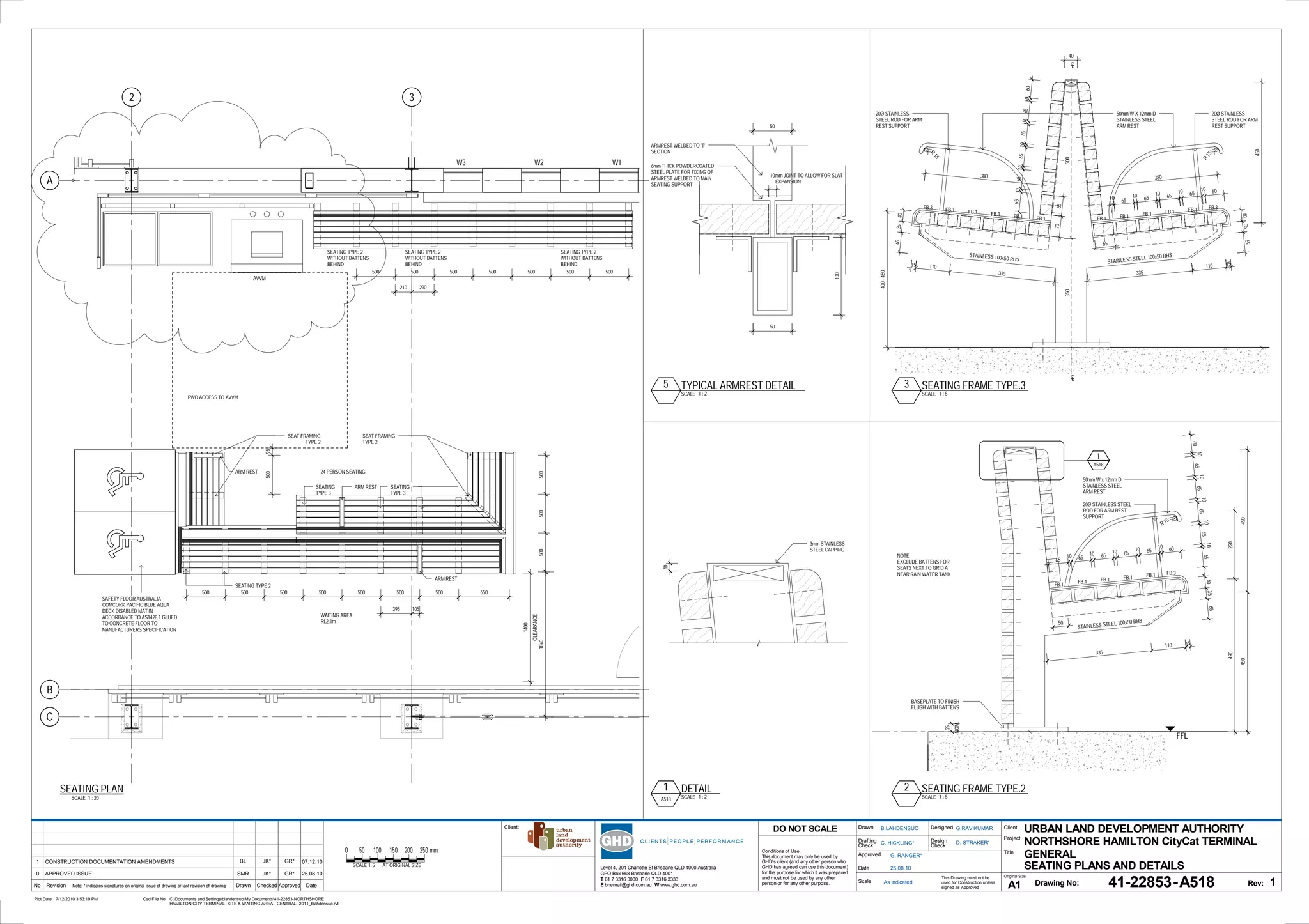
This document provides a cover sheet and legend for architectural drawings for a new CityCat ferry terminal. It includes a project description, list of drawings, abbreviations legend and general notes. The legend defines abbreviations used on the drawings and notes provide guidance on materials and construction methods. The project involves construction of a new ferry terminal with waiting area, gangway, pontoon and associated infrastructure at Macarthur Avenue, Hamilton QLD.
Prefabrication for improving Sustainability and Economics of Civil Engineerin...Ankit Singhai
Use of Prefabrication for improving Sustainability and Economics of Civil Engineering Projects
Studied the advantages of using prefabrication and modular construction over traditional construction practices.
Also, identified the hindrances in its application, and possible solution
Design of Various Types of Industrial Buildings and Their ComparisonIRJESJOURNAL
ABSTRACT :- In this paper Industrial Steel truss Building of 14m x 31.50m, 20m x 50m, 28m x 70m and bay spacing of 5.25m, 6.25m and 7m respectively having column height of 6m is compared with Pre-engineering Buildings of same dimension. Design is based on IS 800-2007 (LSM) Load considered in modeling are Dead load, Live Load, Wind load along with the combinations as specified in IS. Analysis results are observed for column base as hinge base. Results of Industrial steel truss buildings are compared with the same dimensions of Pre-Engineering Building
Reuse of wastewater as a climate mitigation strategy - Bengaluru and its hint...biometrust
The Government of Karnataka proposes to pump 770 MLD of treated wastewater from Bengaluru City to the neighbouring drought-prone districts of Kolar, Chikkaballapur and Bengaluru Rural. The treated wastewater will fill up 134 tanks in these districts and will benefit the farmers by increasing the groundwater table through recharge from the tanks. This is part of the KC valley pumping scheme. As part of this project, farmer interviews were conducted around lakes yet to receive treated wastewater (Holali, Markalaghatta), lakes rejuvenated through World Bank JSYS project (Pichguntlahalli, Hosakere) and a lake that has received treated wastewater (Lakshmisagara). A total of 10-15 farmers were interviewed near each lake. Secondary data on drought, climate change, and wastewater reuse was also collected from KSNDMC and other available case studies. An Environment Impact Assessment (EIA) was also conducted in 4 lakes to document and understand the link between the lake, water, vegetation and the treated wastewater. The key findings of the project have been shared in this report.
Understanding Gridshell Structures - Mannheim Multihalle Case StudyAbhimanyu Singhal
The Mannheim Multihalle is a physical proof that little more than simple math and a detailed model could be used to create a structure with both organic materials and form.
The tube is the name given to the systems where in order to resist lateral loads (wind, seismic, etc.) a building is designed to act like a three-dimensional hollow tube. The system was introduced by Fazlur Rahman Khan while at Skidmore, Owings and Merrill's (SOM) Chicago office. The first example of the tube’s use is the 43-story Khan-designed DeWitt-Chestnut Apartment Building in Chicago, Illinois, completed in 1963.
The system can be constructed using steel, concrete, or composite construction (the discrete use of both steel and concrete). It can be used for office, apartment and mixed-use buildings. Most buildings in excess of 40 stories constructed in the United States since the 1960s are of this structural type. The tube system concept is based on the idea that a building can be designed to resist lateral loads by designing it as a hollow cantilever perpendicular to the ground.
In the simplest incarnation of the tube, the perimeter of the exterior consists of closely spaced columns that are tied together with deep beams through moment connections. This assembly of columns and beams forms a rigid frame that amounts to a dense and strong structural wall along the exterior of the building.
This exterior framing is designed sufficiently strong to resist all lateral loads on the building, thereby allowing the interior of the building to be simply framed for gravity loads. Interior columns are comparatively few and located at the core.
The distance between the exterior and the core frames is spanned with beams or trusses. This maximizes the effectiveness of the perimeter tube by transferring some of the gravity loads within the structure to it and increases its ability to resist overturning due to lateral loads.
Since 1963, a new structural system of framed tubes appeared in skyscraper design and construction.
Fazlur Khan defined the framed tube structure as "a three dimensional space structure composed of three, four, or possibly more frames, braced frames, or shear walls, joined at or near their edges to form a vertical tube-like structural system capable of resisting lateral forces in any direction by cantilevering from the foundation."Closely spaced interconnected exterior columns form the tube. Horizontal loads, for example wind, are supported by the structure as a whole. About half the exterior surface is available for windows. Framed tubes allow fewer interior columns, and so create more usable floor space. Where larger openings like garage doors are required, the tube frame must be interrupted, with transfer girders used to maintain structural integrity.
The first building to apply the tube-frame construction was the DeWitt-Chestnut apartment building which Khan designed(1963) and was completed in Chicago by 1965. This laid the foundations for the tube structures of many other later skyscrapers, including his own John Hancock Center and Willis Tower, and can been seen in the construction of the World Trade Cente
The bundled tube structure meant that "buildings no longer need be boxlike in appearance: they could become sculpture." Hybrids. Hybrids include a varied category of structures where the basic concept of tube is used, and supplemented by other structural support(s).
framed tube structure
structure tube furniture
structure tube canada
tube structural system
tube structure design
tube frame building kits
tube structure buildings
tube framed buildings
interesting civil engineering topics
civil engineering topics for presentation
seminar topics pdf
best seminar topics for civil engineering
civil seminar topics ppt
civil engineering seminar topics 2019
seminar topics for mechanical engineers
mechanical engineering seminar topics 2018
Sachpazis: Raft Foundation Analysis and Design for a two Storey House Project...Dr.Costas Sachpazis
Sachpazis: Raft Foundation Analysis and Design for a two Storey House Project
In accordance with BS8110: PART 1: 1997 and Code of Practice for Geotechnical design and the U.K. recommended values
Hello everyone! I am thrilled to present my latest portfolio on LinkedIn, marking the culmination of my architectural journey thus far. Over the span of five years, I've been fortunate to acquire a wealth of knowledge under the guidance of esteemed professors and industry mentors. From rigorous academic pursuits to practical engagements, each experience has contributed to my growth and refinement as an architecture student. This portfolio not only showcases my projects but also underscores my attention to detail and to innovative architecture as a profession.
Between Filth and Fortune- Urban Cattle Foraging Realities by Devi S Nair, An...Mansi Shah
This study examines cattle rearing in urban and rural settings, focusing on milk production and consumption. By exploring a case in Ahmedabad, it highlights the challenges and processes in dairy farming across different environments, emphasising the need for sustainable practices and the essential role of milk in daily consumption.
You could be a professional graphic designer and still make mistakes. There is always the possibility of human error. On the other hand if you’re not a designer, the chances of making some common graphic design mistakes are even higher. Because you don’t know what you don’t know. That’s where this blog comes in. To make your job easier and help you create better designs, we have put together a list of common graphic design mistakes that you need to avoid.
White wonder, Work developed by Eva TschoppMansi Shah
White Wonder by Eva Tschopp
A tale about our culture around the use of fertilizers and pesticides visiting small farms around Ahmedabad in Matar and Shilaj.
Dive into the innovative world of smart garages with our insightful presentation, "Exploring the Future of Smart Garages." This comprehensive guide covers the latest advancements in garage technology, including automated systems, smart security features, energy efficiency solutions, and seamless integration with smart home ecosystems. Learn how these technologies are transforming traditional garages into high-tech, efficient spaces that enhance convenience, safety, and sustainability.
Ideal for homeowners, tech enthusiasts, and industry professionals, this presentation provides valuable insights into the trends, benefits, and future developments in smart garage technology. Stay ahead of the curve with our expert analysis and practical tips on implementing smart garage solutions.
Top 5 Indian Style Modular Kitchen DesignsFinzo Kitchens
Get the perfect modular kitchen in Gurgaon at Finzo! We offer high-quality, custom-designed kitchens at the best prices. Wardrobes and home & office furniture are also available. Free consultation! Best Quality Luxury Modular kitchen in Gurgaon available at best price. All types of Modular Kitchens are available U Shaped Modular kitchens, L Shaped Modular Kitchen, G Shaped Modular Kitchens, Inline Modular Kitchens and Italian Modular Kitchen.
Transforming Brand Perception and Boosting Profitabilityaaryangarg12
In today's digital era, the dynamics of brand perception, consumer behavior, and profitability have been profoundly reshaped by the synergy of branding, social media, and website design. This research paper investigates the transformative power of these elements in influencing how individuals perceive brands and products and how this transformation can be harnessed to drive sales and profitability for businesses.
Through an exploration of brand psychology and consumer behavior, this study sheds light on the intricate ways in which effective branding strategies, strategic social media engagement, and user-centric website design contribute to altering consumers' perceptions. We delve into the principles that underlie successful brand transformations, examining how visual identity, messaging, and storytelling can captivate and resonate with target audiences.
Methodologically, this research employs a comprehensive approach, combining qualitative and quantitative analyses. Real-world case studies illustrate the impact of branding, social media campaigns, and website redesigns on consumer perception, sales figures, and profitability. We assess the various metrics, including brand awareness, customer engagement, conversion rates, and revenue growth, to measure the effectiveness of these strategies.
The results underscore the pivotal role of cohesive branding, social media influence, and website usability in shaping positive brand perceptions, influencing consumer decisions, and ultimately bolstering sales and profitability. This paper provides actionable insights and strategic recommendations for businesses seeking to leverage branding, social media, and website design as potent tools to enhance their market position and financial success.
1. Level 4, 201 Charlotte St Brisbane QLD 4000 Australia
GPO Box 668 Brisbane QLD 4001
T 61 7 3316 3000 F 61 7 3316 3333
E bnemail@ghd.com.au W www.ghd.com.auNo Revision Note: * indicates signatures on original issue of drawing or last revision of drawing Drawn Checked Approved Date
Conditions of Use.
This document may only be used by
GHD's client (and any other person who
GHD has agreed can use this document)
for the purpose for which it was prepared
and must not be used by any other
person or for any other purpose. Scale
Drawn
Drafting
Approved
Date
Check
Designed
Design
Check
DO NOT SCALE Client
Project
Title
Original Size
A1 Drawing No: Rev:
This Drawing must not be
used for Construction unless
signed as Approved
Plot Date: Cad File No:
-
Client:
7/12/2010 3:48:30 PM C:Documents and SettingsblahdensuoMy Documents41-22853-NORTHSHORE
HAMILTON CITY TERMINAL- SITE & WAITING AREA - CENTRAL -2011_blahdensuo.rvt
URBAN LAND DEVELOPMENT AUTHORITY
NORTHSHORE HAMILTON CityCat TERMINAL
A000
J.BROWNE G.RAVIKUMAR
D. STRAKER*
G. RANGER*
COVER SHEET
41-22853
25.08.10
C. HICKLING*
BL JK* GR*
SMR JK* GR*
GENERAL
1
APPROVED ISSUE0 25.08.10
CONSTRUCTION DOCUMENTATION AMENDMENTS1 07.12.10
URBAN LAND DEVELOPMENT AUTHORITY
NORTHSHORE HAMILTON CityCat TERMINAL
41-22853
SITE ADDRESS:
RP/SP:
LOT No:
COUNCIL:
MACARTHUR AVENUE,
HAMILTON QLD, 4007
224971
115
BRISBANE CITY COUNCIL
NEW CityCat TERMINAL
41-22853- M100 GENERAL PILE SETOUT PLAN & SCHEDULE
41-22853- M101 GENERAL PILE ELEVATIONS
41-22853- M102 GENERAL PILE DETAILS
41-22853- M103 GENERAL PILE CATHODIC PROTECTION DETAILS
41-22853- M200 WAITING AREA SLAB PLAN
41-22853- M201 WAITING AREA SLAB REINFORCEMENT PLAN
41-22853- M202 WAITING AREA SLAB SECTIONS & DETAILS
41-22853- M300 GANGWAY FRAMING PLANS & SECTIONS
41-22853- M301 GANGWAY DETAILS SHEET 1
41-22853- M302 GANGWAY DETAILS SHEET 2
41-22853- M400 PONTOON GENERAL ARRANGEMENT & SECTIONS
41-22853- M401 PONTOON FRAMING PLAN & SECTIONS
41-22853- M402 PONTOON STIFFENER PLAN & SECTIONS
41-22853- M403 PONTOON TYPICAL DETAILS SHEET 1
41-22853- M404 PONTOON TYPICAL DETAILS SHEET 2
41-22853- M405 PONTOON FENDER FRAME DETAILS
41-22853- M406 PONTOON BALLAST PLAN & SECTION
3. STRUCTURES
41-22853- S001 GENERAL STRUCTURAL NOTES
41-22853- S100 WAITING AREA STRUCTURAL ROOF PLANS
41-22853- S101 WAITING AREA ELEVATIONS & SECTIONS
41-22853- S102 WAITING AREA ROOF FRAMING DETAILS
41-22853- S200 PONTOON ROOF FRAMING & PURLIN PLANS
41-22853- S201 PONTOON TYPICAL SECTIONS
41-22853- S202 PONTOON ROOF FRAMING DETAILS
41-22853- S300 GENERAL BALUSTRADE AND SCREEN DETAILS
4. ELECTRICAL
41-22853- E000 GENERAL LEGEND
41-22853- E001 GENERAL SITE PLAN - SHEET 1 OF 2
41-22853- E002 GENERAL SITE PLAN - SHEET 2 OF 2
41-22853- E003 GENERAL LIGHTING LAYOUT
41-22853- E004 GENERAL CCTV & COMMUNICATION SYSTEM LAYOUT
41-22853- E005 GENERAL POWER & COMMS LAYOUT
41-22853- E006 GENERAL SCHEMATICS & DETAILS
5. HYDRAULICS
41-22853- H001 GENERAL LOCALITY PLAN, LEGENDS & NOTES
41-22853- H002 GENERAL DRAINAGE & WATER SERVICES LAYOUT
6. LANDSCAPE
41-22853- L001 GENERAL PLANTING LAYOUT PLAN AND DETAILS
41-22853- L010 GENERAL IRRIGATION LAYOUT PLAN AND DETAILS
1. ARCHITECTURAL
41-22853- A000 GENERAL COVER SHEET
41-22853- A001 GENERAL LEGEND AND NOTES
41-22853- A003 TERMINAL SITE PLAN
41-22853- A004 TERMINAL ROOF PLAN
41-22853- A005 TERMINAL ELEVATIONS & SECTION SHEET 1
41-22853- A006 TERMINAL SIGNAGE PLAN
41-22853- A101 WAITING AREA PLANS
41-22853- A110 WAITING AREA ELEVATIONS
41-22853- A120 WAITING AREA SECTIONS
41-22853- A130 WAITING AREA WALL SECTIONS SHEET 1
41-22853- A131 WAITING AREA WALL SECTIONS SHEET 2
41-22853- A140 WAITING AREA CONSTRUCTION DETAILS SHEET 1
41-22853- A141 WAITING AREA CONSTRUCTION DETAILS SHEET 2
41-22853- A150 WAITING AREA WATER TANK DETAILS
41-22853- A151 WAITING AREA BIN ENCLOSURE AND GO-CARD MACHINE
41-22853- A201 GANGWAY PLANS
41-22853- A210 GANGWAY SECTIONS & ELEVATIONS
41-22853- A240 GANGWAY CONSTRUCTION DETAILS
41-22853- A301 PONTOON PLANS
41-22853- A310 PONTOON ELEVATIONS
41-22853- A320 PONTOON SECTIONS
41-22853- A330 PONTOON WALL SECTIONS
41-22853- A401 RAMPS RAMP PLAN, ELEVATION & SECTION DETAIL
41-22853- A510 GENERAL BALUSTRADE DETAILS SHEET 1
41-22853- A512 GENERAL BALUSTRADE DETAILS SHEET 2
41-22853- A514 GENERAL GATE 1 DETAILS SHEET 1
41-22853- A515 GENERAL GATE DETAILS SHEET 2
41-22853- A517 GENERAL TIMETABLE AND LASER CUT PANEL
41-22853- A518 GENERAL SEATING PLANS AND DETAILS
41-22853- A519 WAITING AREA WINDOW AND DOOR SCHEDULE
41-22853- A900 GENERAL SIGNAGE DETAILS
41-22853- A910 WAITING AREA PANELLING DETAIL
2. MARINE
41-22853- M001 GENERAL MARINE NOTES
BRISBANE RIVER
2. SET
OUT
??° PITCH
2400
ACT
23
ANNOTATION LEGEND
ANNOTATION ABBREVIATION (REFER LEGEND)
GATE NUMBER
CEILING TYPE AND HEIGHT
ROOF PLAN PITCH AND DIRECTION
ABC
low
high
G
FINISHABC
2400
ACT
CEILING LEGEND
CEILING TYPES:
PAINTED 13mm PLASTERBOARD
PAINTED WET AREA PLASTERBOARD
PAINTED 6mm FIBRE CEMENT
SUSPENDED ACOUSTIC CEILING TILES
SUSPENDED CEILING TILE
UNDERSIDE OF ROOF OR SLAB ABOVE
COLORBOND ACOUSTIC METAL SYSTEM
EXISTING CEILING MADE GOOD
PAINTED OFF FORM CONCRETE
PBD
PBD.1
FC
ACT
SCT
U/S
OFF
CEILING TYPE AND HEIGHT
CEILING SETOUT POINT
MATERIAL TYPES
MEDIUM DENSITY FIBRE BOARD
FIBRE CEMENT
PLASTERBOARD/PLASTER
CONCRETE
TILING
EARTH
SAND
GROUT
INSULATION
1. SEPARATE ALL DISSIMILAR METALS FROM EACH OTHER BY
INSERTING DURABLE ELECTRICALLY INSULATING MATERIAL
AT EVERY CONTACT POINT. SEPARATION METHODS MAY
INCLUDE WASHERS AND SLEEVES ON BOLTS, INSERTS
BETWEEN MATING SURFACES AND OTHER METHODS AS
APPROVED.
2. PREVENT CONTACT OF ALUMINIUM WITH ANY CONCRETE,
CEMENT, GROUT OR OTHERWISE ALKALINE SURFACES.
NOTES:
Level 4, 201 Charlotte St Brisbane QLD 4000 Australia
GPO Box 668 Brisbane QLD 4001
T 61 7 3316 3000 F 61 7 3316 3333
E bnemail@ghd.com.au W www.ghd.com.auNo Revision Note: * indicates signatures on original issue of drawing or last revision of drawing Drawn Checked Approved Date
Conditions of Use.
This document may only be used by
GHD's client (and any other person who
GHD has agreed can use this document)
for the purpose for which it was prepared
and must not be used by any other
person or for any other purpose. Scale
Drawn
Drafting
Approved
Date
Check
Designed
Design
Check
DO NOT SCALE Client
Project
Title
Original Size
A1 Drawing No: Rev:
This Drawing must not be
used for Construction unless
signed as Approved
Plot Date: Cad File No:
-
Client:
1 : 1
7/12/2010 3:48:31 PM C:Documents and SettingsblahdensuoMy Documents41-22853-NORTHSHORE
HAMILTON CITY TERMINAL- SITE & WAITING AREA - CENTRAL -2011_blahdensuo.rvt
URBAN LAND DEVELOPMENT AUTHORITY
NORTHSHORE HAMILTON CityCat TERMINAL
A001
B.LAHDENSUO G. RAVIKUMAR
D. STRAKER*
G. RANGER*
LEGEND AND NOTES
41-22853
25.08.10
C. HICKLING*
BL JK* GR*
DW JK* GR*
GENERAL
1
APPROVED ISSUE0 25.08.10
CONSTRUCTION DOCUMENTATION AMENDMENTS1 07.12.10
LEGEND
ABBREVIATION DESCRIPTION
RW TANK CUSTOM MANUFACTURED 1000L STAINLESS STEEL 316 GRADE RAINWATER TANK
SEA APPROVED SEALANT
SL LED STRIP LIGHTING
SMP COLORBOND BOX GUTTER SUMP
SN SIGNAGE
SP 'SANYO' HIP-210NKHE6 SOLAR PANEL 1580mm x 798mm WITH SUNLOCK MOUNTING
SYSTEM - FIXED TO MANUFACTURER'S SPECIFICATION
SPT.1 100mmL x 60mmD COLORBOND STEEL DOWNPIPE SPITTER TO GUTTER
SPT.2 100mmL x 60mmD COLORBOND STEEL OVERFLOW SPITTER TO GUTTER
SS STAINLESS STEEL
TGSI-A WARNING TACTILE GROUND SURFACE INDICATOR INSTALLED IN ACCORDANCE WITH
AS1428.1-2009, AS1428.2 & AS 1428.4-2009
TH TOPHAT SECTION
UHMWPE 3mm MIN THICKNESS ULTRA HIGH MOLECULAR WEIGHT POLYETHELYNE SEPARATION
FOR DISSIMILAR METALS
VB VERTICAL BRACING
LEGEND
ABBREVIATION DESCRIPTION
ADF COMCORK AQUADECK 3mm FLOORING 'DENIM WE1030' - 'R12' SLIP RESISTANCE
AF COLORBOND APRON FLASHING
AGG EXPOSED AGGREGATE FINISH - HANSON 'SPECTRUM-X' COLOUR TO MATCH EXISTING
(C.O.S), SAND BLASTED WITH 'CCS STAIN BLOCK' PENETRATING SEALANT
AHD AUSTRALIAN HEIGHT DATUM
AL ALUMINIUM
ALC.1 ALPOLIC OR EQUIVALENT 4mm COLOUR 1 FIXED TO MANUFACTURERS
SPECIFICATIONS
ALC.2 ALPOLIC OR EQUIVALENT 4mm COLOUR 2 FIXED TO MANUFACTURERS
SPECIFICATIONS
ALC.3 ALPOLIC OR EQUIVALENT 4mm COLOUR 3 FIXED TO MANUFACTURERS
SPECIFICATIONS
ALC.4 ALPOLIC OR EQUIVALENT 4mm COLOUR 4 FIXED TO MANUFACTURERS
SPECIFICATIONS
AP ACCESS PANEL
BAL.1 1400mm HIGH STAINLESS STEEL BALUSTRADE
BAL.2 13.52mm THICK HEAT STRENGTHENED LAMINATE GLASS. FLAT POLISHED
BAL.3 1100mm HIGH STAINLESS STEEL BALUSTRADE TO GANGWAY
BAL.4 1100mm HIGH STAINLESS STEEL BALUSTRADE TO PONTOON
BG 450W x 125D COLORBOND BOX GUTTER LINING SHEET 0.7 BMT
BPF BIRD PREVENTION SYSTEM - BIRD SHOCK - FLEX TRACK
BRs
CBC COLORBOND CAPPING
CBF COLORBOND FASCIA CAPPING
CBP COLORBOND BARGE CAPPING
CCTV CCTV CAMERA (SEE ELECTRICAL LEGEND E103)
CJ CONTROL JOINT
CL CENTRE LINE
COL STRUCTURAL COLUMN
DG DIGITAL CLOCK
DP.1 100mm DIA uPVC TANK CONNECTION (FF INDICATES FIRST FLUSH DEVICE)
DP.2 100 x 60 STAINLESS STEEL 316 GRADE RECTANGULAR DOWNPIPE
ECB ELECTRICAL CUPBOARD
EL EMERGENCY LUMINAIRE
FAS STATIC LINE FALL ARREST SYSTEM
FB.1 ALTIFORM FURNITURE BATTENS - GLASS REINFORCED HDPE PLASTIC 38x63.5 POLY SR
- MID GREY
FB.2 ALTIFORM FURNITURE BATTENS - GLASS REINFORCED HDPE PLASTIC 38x88.5 POLY SR
- MID GREY
FB.3 ALTIFORM FURNITURE BATTENS - GLASS REINFORCED HDPE PLASTIC 38x60.0 POLY SR
- BULL NOSED - MID GREY
FC FIBRE CEMENT SHEETING 6mm PAINTED
FG FIXED GLASS G. JAMES. 450 SERIES SHOP FRONT GLAZING WITH 13.52mm HEAT
STRENGTHENED LAMINATE SAFETY GLASS
FGW FIXED GLASS WINDOW G. JAMES 100x25 GLAZING SECTION
FIN.1 DECORATIVE FIN ELEMENT TYPE 1
FIN.2 DECORATIVE FIN ELEMENT TYPE 2
FLG FLASHING
G.1 SLIDING GATE - HANGING CUSTOM MANUFACTURED MAIN ENTRANCE GATE
GALV GALVANISED
GBD SPANDEK GUTTER BOARD ON 25 x 3mm EQUAL ANGLE SUPPORTS FIXED AT MAX
450mm CENTRES
GU.1 GUTTER TO WAITING AREA ROOF
GU.2 GUTTER TO PONTOON ROOF
HAF HONED CONCRETE FINISH - HANSON TERACRETE 'PARISIENNE' - WITH 'CCS STAIN
BLOCK' PENETRATING SEALANT
HDR.1 STAINLESS STEEL 316 GRADE HAND RAIL
HDR.2 STAINLESS STEEL 316 GRADE ACCESSIBLE HANDRAIL WITH KICK RAIL TO COMPLY
WITH AS1428
HP HIGH POINT
INS.1 GREEN INSULATION REFLECTA-GUARD
INS.2 BRADFORD ENVIROSEAL ROOF/METAL WALL (SARKING)
INS.3 BRADFORD GOLD WALL BATTS
LCP STAINLESS STEEL 316 GRADE LASER CUT PANELS
LDR LADDER RESTRAINT POINT
LVR LOUVRE
LVR.1 SHADE LOUVRE, HUNTER DOUGLAS ALUMINIUM AEROBRISE '150mm x 25mm' DEEP
FACE FIXED - NOT USED THIS TERMINAL
LVR.2 LOUVRE, HUNTER DOUGLAS ALUMINIUM EXTRUDED SUN LOUVRES 80RX-80mmW X
23mmD FIXED TO MOUNTING BRACKETS @ 50mm C/C
MSSB MECHANICAL SERVICES SWITCHBOARD
OF.1 100 X 60 STAINLESS STEEL 316 GRADE RECTANGULAR OVERFLOW
PCP FIBRE GLASS PILE CAP (REFER MARINE ENGINEERS DRAWINGS)
PF PORTAL FRAME (REFER STRUCTURAL ENGINEERS DRAWINGS)
PFC PARALLEL FLANGE CHANNEL
PU PURLIN
PWD PERSONS WITH DISABILITIES
PWY CLEARSONICS PEDESTAL WAYPHONE 210mmW x 1475mmH x 130mmD
RA RAFTER
RS ROLLER SHUTTER
RSH.1 LYSAGHT LONGLINE 305, COLORBOND, PLAIN FLAT PANS - 0.70mm BMT - ROOF
SHEETING
RSH.2 KINGSPAN INSULATED TRAPEZOIDAL ROOF PANEL SYSTEM (KS-1000-RW), 95mm
OVERALL THICKNESS OR EQUAL
GATE SCHEDULE
MARK HEIGHT WIDTH GATE TYPE GATE FINISH
FRAME
TYPE FRAME FINISH COMMENTS
TYPE
COMMENTS
G1 3100 4130 ALUMINIUM WELDED ANGLES POWDERCOATED
ALUMINIUM
ALUMINIUM
RHS
POWDERCOATED
ALUMINIUM
TOP HUNG SLIDING WAITING AREA
G2 1100 1080 WELDED FLAT PLATE STAINLESS STEEL RHS STAINLESS STEEL SWING PONTOON
G3 1100 1400 WELDED FLAT PLATE STAINLESS STEEL RHS STAINLESS STEEL SLIDING WITH WHEEL ASSEMBLY PONTOON
G4 1100 1400 WELDED FLAT PLATE STAINLESS STEEL RHS STAINLESS STEEL SLIDING WITH WHEEL ASSEMBLY PONTOON
G5 1100 1400 WELDED FLAT PLATE STAINLESS STEEL RHS STAINLESS STEEL SLIDING WITH WHEEL ASSEMBLY PONTOON
G6 1100 1400 WELDED FLAT PLATE STAINLESS STEEL RHS STAINLESS STEEL SLIDING WITH WHEEL ASSEMBLY PONTOON
3. REFER A910 FOR ALPOLIC ELEVATIONS
AND FEATURE LIGHTING POSITIONS
3. TAP
IL
1.48
Gully Pit
SL 4.20
Gully Pit
SL 4.08
Height=4m
Height=5m
Height=5m
Height=5m
Height=5m
Height=5m
Trunk =.1m
Trunk =.1m
Trunk =.1m
Trunk =.1m
Trunk =.1m
Trunk =.1m
Type =GU
Type =GU
Type =GU
Type =GU
Type =GU
Type =GU
Spread=1 rad
Spread=1 rad
Spread=1 rad
Spread=1 rad
Spread=1 rad
Spread=1 rad
-8.00
-7.50
-7.00
-6.50
-6.00
-5.50
-5.00
-4.50
-4.00
-3.50
-3.00
-2.50
-2.00
-1.50
-1.00
-0.50
0.00
0.50
1.00
1.50
2.00
2.50
IL
3.08
IL
3.08
IL
3.23
SW 3-1
SW 3-0
SW 3-1-1
SW 3-2
SW 4-1
SW 4-2
750mmdiaRCP
375mm
dia RCP
750mm
dia
RCP
450 mm dia RCP
450mmdiaRCP
750 DICAL
750 DICAL
4.07
4.79
3.66
3.59
5.41
4.13
3.43
3.32
4.18
4.10
3.93
3.81
3.75
4.40
4.06
3.25
3.49
3.58
3.69
3.77
2.63
3.00
3.33
3.65
4.09
3.85
2.97
2.90
2.97
2.82
2.91
3.48
3.71
3.65
3.94
3.79
Rock Swale
Rock Pitching
Comms Pit
Gate
Gate
Stone Paving
Tap
Bollards
Bollards
Bollards
Sign
Sign
Post
Post
Post
Post
Sign
Sign
Stormwater Headwall
Path (Exp Ag)
Path (Exp Ag)
CAFE
Path (Tiles)
Art
Retaining Wall
Retaining Walls
OVAL
Substation
Elec Pits
NEW ROAD BY OTHERS
Elec for Future
IL
0.06
IL
1.23
IL
0.20
IL
0.19
IL
1.92
IL
1.43
IL
1.45
IL
1.70
FSL 3.13
FSL 2.82
FSL 2.93
WAITING AREA
PONTOON
BRISBANE RIVER
EXISTING PARK
MAKE GOOD EXISTING ROCK REVETMENT
EXISTING ARTIFICIAL BEACH
EXISTING LANDSCAPING
EXISTING VEGETATION
GANGWAY
EXISTING WHARF
NEW ACCESS RAMP
A005
1
A005
2
1 2 3 4 5
A
C
B
D
E
F
6 7 8 9
WATERAREAALLOCATIONBOUNDARY
WATER AREA ALLOCATION BOUNDARY
LOT 115
SP224971
RC
AL
RL 2.1
23mLONG,2.0mCLEARWALKWAY
0.9m FREEBOARD
21450 x 5000mm
STEEL
457 x 12.7 STEEL PILES
800 x 16 STEEL PILES
3
2
POINTONBOUNDARYOF
LOT115
E58262.010,N161492.407
1
4
TIDAL BOUNDARY (VIDE SL8655)
GABIONS
ROCK
LOOSE ROCKS
LOOSE ROCKS
SILTED AREA
10 11
HAT
MHWS
LAT
74600
POINT 8 ON SP
224971
3307
14°43'30"
40755
14°42'
3
A005
RELOCATE
EXISTING SEAT
MAKE GOOD EXISTING LANDSCAPE
DEMOLISH EXISTING VEGETATION
MAKE GOOD EXISTING LANDSCAPE
MAKE GOOD EXISTING PATH
MAKE GOOD EXISTING ROCK REVETMENT
REFER TO MARINE DRAWINGS FOR
REQUIREMENTS FOR EXISTING GABIONS
AGG
AGG
SLAB EDGE
31148
1500
RELOCATED SEAT
NEW BICYCLE PARKING
457 x 12.7 STEEL PILES
SETOUT POINT 2 (REFER DETAIL)
SETOUT POINT 1 (REFER DETAIL)
1500 1500
RETAIN EXISTING
SEAT
RETAIN EXISTING VEGETATION
SEAT SETOUT
2945 70°
1.65
1.06
0.0
-0.85
-1.24
2.89
2.30
1.24
0.39
0.0
AHD LAT
HAT
MHWS
AHD
MLWS
LAT
4
C
E 58298.441
N 161470.648
COLUMN CENTERLINE LOCATED
ON GRID INTERSECTIONS
2
A
COLUMN CENTERLINE LOCATED
ON GRID INTERSECTIONS
E 58293.232
N 161479.147
CONTRACTORS SITE ENTRY
TEMPORARY
FENCE
CONTRACTOR TO MAKE
GOOD PARK AS EXISTING
UP ON COMPLETION
RETAIN EXISTING
FENCE
RETAIN EXISTING
FENCE
REMOVE FENCE AND
PROVIDE GATE AS
REQUIRED UPON
APPROVAL FROM
PRINCIPAL
TEMPORARYFENCE
CONTRACTORS SIDE
FENCE
MAKE GOOD EXISTING TURF
CONTRACTORS SITE
FENCE
16500
PROPOSED TERMINAL
SITE SHED/STORAGE
35800
61500
22195
23900
36700
Level 4, 201 Charlotte St Brisbane QLD 4000 Australia
GPO Box 668 Brisbane QLD 4001
T 61 7 3316 3000 F 61 7 3316 3333
E bnemail@ghd.com.au W www.ghd.com.auNo Revision Note: * indicates signatures on original issue of drawing or last revision of drawing Drawn Checked Approved Date
Conditions of Use.
This document may only be used by
GHD's client (and any other person who
GHD has agreed can use this document)
for the purpose for which it was prepared
and must not be used by any other
person or for any other purpose. Scale
Drawn
Drafting
Approved
Date
Check
Designed
Design
Check
DO NOT SCALE Client
Project
Title
Original Size
A1 Drawing No: Rev:
This Drawing must not be
used for Construction unless
signed as Approved
Plot Date: Cad File No:
-
Client:
As indicated
7/12/2010 3:48:33 PM C:Documents and SettingsblahdensuoMy Documents41-22853-NORTHSHORE
HAMILTON CITY TERMINAL- SITE & WAITING AREA - CENTRAL -2011_blahdensuo.rvt
URBAN LAND DEVELOPMENT AUTHORITY
NORTHSHORE HAMILTON CityCat TERMINAL
A003
J.BROWNE G.RAVIKUMAR
D. STRAKER*
G. RANGER*
SITE PLAN
41-22853
25.08.10
C. HICKLING*
DW JK* GR*
BL JK* GR*
TERMINAL
1
APPROVED ISSUE0 25.08.10
CONSTRUCTION DOCUMENTATION AMENDMENTS1 07.12.10
SCALE 1 : 200
TERMINAL SITE PLAN
0
SCALE 1: AT ORIGINAL SIZE
2000 4000 6000 8000 10000mm
200
NOTE:
1. CONTRACTOR'S SITE TO BE CONFIRMED BY
ULDA
2. ALL LEVELS MEASURED TO AHD
3. HORIZONTAL DATUM BCSG02
4. LANDWARD BOUNDARY AND COASTAL
MANAGEMENT DISTRICT COINCIDES WITH
HAT
5. REFER TO A001 FOR DESIGN PARAMETERS
WATER ALLOCATION SETOUT TABLE
SETOUT POINT No. EASTING NORTHING
1
2
58248.116 161439.5273
58320.266 161420.571
4
HIGHEST ASTRONOMICAL TIDE (H.A.T.)
MEAN HIGH WATER SPRINGS (M.H.W.S.)
LOWEST ASTRONOMICAL TIDE (L.A.T.)
LEGEND
CONTOUR LINES
SCALE 1 : 20
SETOUT POINT 2
SCALE 1 : 20
SETOUT POINT 1
58334.661
58261.730 161491.343
161475.360
4. 1110
PONTOON
BRISBANE RIVER
23mGANGWAY
WAITING AREA
1 2 3 4 5
A
C
B
D
E
F
6 7 8 9
SOLAR PANELS
FALL
FALL
FALL
FALL FALLFALL
WATERAREAALLOCATIONBOUNDARY
10 11
LOTBOUNDARY
EXISTING WHARF
Level 4, 201 Charlotte St Brisbane QLD 4000 Australia
GPO Box 668 Brisbane QLD 4001
T 61 7 3316 3000 F 61 7 3316 3333
E bnemail@ghd.com.au W www.ghd.com.auNo Revision Note: * indicates signatures on original issue of drawing or last revision of drawing Drawn Checked Approved Date
Conditions of Use.
This document may only be used by
GHD's client (and any other person who
GHD has agreed can use this document)
for the purpose for which it was prepared
and must not be used by any other
person or for any other purpose. Scale
Drawn
Drafting
Approved
Date
Check
Designed
Design
Check
DO NOT SCALE Client
Project
Title
Original Size
A1 Drawing No: Rev:
This Drawing must not be
used for Construction unless
signed as Approved
Plot Date: Cad File No:
-
Client:
1 : 100
7/12/2010 3:48:35 PM C:Documents and SettingsblahdensuoMy Documents41-22853-NORTHSHORE
HAMILTON CITY TERMINAL- SITE & WAITING AREA - CENTRAL -2011_blahdensuo.rvt
URBAN LAND DEVELOPMENT AUTHORITY
NORTHSHORE HAMILTON CityCat TERMINAL
A004
J.BROWNE G.RAVIKUMAR
D. STRAKER*
G. RANGER*
ROOF PLAN
41-22853
25.08.10
C. HICKLING*
BL JK* GR*
BL JK* GR*
TERMINAL
1
APPROVED ISSUE0 25.08.10
CONSTRUCTION DOCUMENTATION AMENDMENTS1 07.12.10
0
SCALE 1: AT ORIGINAL SIZE
1000 2000 3000 4000 5000mm
100
SCALE 1 : 100
TERMINAL ROOF PLAN
NOTE:
1. REFER ROOF PLANS OF EACH INDIVIDUAL
COMPONENT FOR FURTHER DETAILS
5. 12345
LINE OF RAMP FLOOR BEHIND
BORAL OR EQUIVALENT SPLIT FACE BLOCK
6 7 8 9
A CB
D E F
WAITING AREA GANGWAY
PONTOON
1.65
1.06
0.0
-0.85
-1.24
HAT
MHWS
AHD
MLWS
LAT
Level 4, 201 Charlotte St Brisbane QLD 4000 Australia
GPO Box 668 Brisbane QLD 4001
T 61 7 3316 3000 F 61 7 3316 3333
E bnemail@ghd.com.au W www.ghd.com.auNo Revision Note: * indicates signatures on original issue of drawing or last revision of drawing Drawn Checked Approved Date
Conditions of Use.
This document may only be used by
GHD's client (and any other person who
GHD has agreed can use this document)
for the purpose for which it was prepared
and must not be used by any other
person or for any other purpose. Scale
Drawn
Drafting
Approved
Date
Check
Designed
Design
Check
DO NOT SCALE Client
Project
Title
Original Size
A1 Drawing No: Rev:
This Drawing must not be
used for Construction unless
signed as Approved
Plot Date: Cad File No:
-
Client:
As indicated
7/12/2010 3:48:44 PM C:Documents and SettingsblahdensuoMy Documents41-22853-NORTHSHORE
HAMILTON CITY TERMINAL- SITE & WAITING AREA - CENTRAL -2011_blahdensuo.rvt
URBAN LAND DEVELOPMENT AUTHORITY
NORTHSHORE HAMILTON CityCat TERMINAL
A005
J.BROWNE G.RAVIKUMAR
D. STRAKER*
G. RANGER*
ELEVATIONS & SECTION SHEET 1
41-22853
25.08.10
C. HICKLING*
BL JK* GR*
SMR JK* GR*
TERMINAL
1
APPROVED ISSUE0 25.08.10
CONSTRUCTION DOCUMENTATION AMENDMENTS1 07.12.10
0
SCALE 1: AT ORIGINAL SIZE
500 1000 1500 2000 2500mm
50
SCALE 1 : 50A003
TERMINAL ELEVATION1
SCALE 1 : 50A003
TERMINAL ELEVATION2
SCALE 1 : 100A003
TERMINAL SECTION3
NOTE: ALL LEVELS MEASURED TO A.H.D.
A003
A003
A003
NOTE:
1. REFER ELEVATION DRAWNIGS OF EACH
INDIVIDUAL COMPONENT FOR FURTHER
DETAILS
6. WAITING AREA
RL2.1m
'NORTHSHORE
HAMILTON' TERMINAL
SIGN
'RUBBISH &
RECYCLE BIN'
SIGN
'NON POTABLE'
SIGN TO TAP
'CERTIFICATE OF
CLASSIFICATION' DISPLAYED
IN TIMETABLE BOARD
ILLUMINATED EXIT SIGN
ABOVE
ILLUMINATED EXIT SIGN
ABOVE
'ELECTRICAL CUPBOARD' SIGN
'NO SMOKING' SIGN
SAFETY FLOOR AUSTRALIA
COMCORK PACIFIC BLUE AQUA DECK
DISABLED MAT IN ACCORDANCE TO
AS1428.1 GLUED TO CONCRETE
FLOOR TO MANUFACTURERS
SPECIFICATION
ILLUMINATED EXIT SIGN
ABOVE
'MOVINGOBJECTSTANDCLEAR'
SIGNTOJUNCTIONOFHINGED
COVERPLATEANDGANGWAY
SPACE ALLOCATED FOR PWD
SIGN ON FLOOR
'NON POTABLE'
SIGN TO TAP
'NO ACCESS' SIGN TO INSIDE OF GATE'NO ACCESS' SIGN TO INSIDE OF GATE
'NORTHSHORE HAMILTON'
TERMINAL SIGN
150mm WIDE YELLOW
COLOUR COMCORK
AQUADECK STRIP TO FLOOR
150mm WIDE YELLOW COLOUR
COMCORK AQUADECK STRIP
TO FLOOR
150mm WIDE YELLOW COLOUR
COMCORK AQUADECK STRIP
TO FLOOR
'RAINWATER TANK
IN USE' SIGN
150mm WIDE YELLOW
COLOUR COMCORK
AQUADECK ARROW TO
FLOOR
150mm WIDE YELLOW
COLOUR COMCORK
AQUADECK ARROW TO
FLOOR
TGSI-A
TGSI-A
TGSI-A
TGSI-A
TGSI-A
Level 4, 201 Charlotte St Brisbane QLD 4000 Australia
GPO Box 668 Brisbane QLD 4001
T 61 7 3316 3000 F 61 7 3316 3333
E bnemail@ghd.com.au W www.ghd.com.auNo Revision Note: * indicates signatures on original issue of drawing or last revision of drawing Drawn Checked Approved Date
Conditions of Use.
This document may only be used by
GHD's client (and any other person who
GHD has agreed can use this document)
for the purpose for which it was prepared
and must not be used by any other
person or for any other purpose. Scale
Drawn
Drafting
Approved
Date
Check
Designed
Design
Check
DO NOT SCALE Client
Project
Title
Original Size
A1 Drawing No: Rev:
This Drawing must not be
used for Construction unless
signed as Approved
Plot Date: Cad File No:
-
Client:
1 : 100
7/12/2010 4:51:55 PM C:Documents and SettingsdwatsonMy Documents41-22853-NORTHSHORE HAMILTON
CITY TERMINAL- SITE & WAITING AREA - CENTRAL -2011_dwatson.rvt
URBAN LAND DEVELOPMENT AUTHORITY
NORTHSHORE HAMILTON CityCat TERMINAL
A006
D. WATSON G. RAVIKUMAR
D. STRAKER*
G. RANGER*
SIGNAGE PLAN
41-22853
25.08.10
C. HICKLING*
BL JK* GR*
GRK JK* GR*
DW JK* GR*
TERMINAL
2
APPROVED ISSUE0 25.08.10
DOOR RELOCATED1 15.09.10
CONSTRUCTION DOCUMENTATION AMENDMENTS2 07.12.10
SCALE 1 : 100
SIGNAGE PLAN
0
SCALE 1: AT ORIGINAL SIZE
1000 2000 3000 4000 5000mm
100
7. A1102A110 4
A110
A110
3
1
HOSE TAP UNDER
SEATING
PEDESTAL WAY
PHONE
AVVM
WAITING AREA
RL2.1m
1
A120
1 2 3 4 5
A
C
3600 3600 3600 2300
6545350
B
24 PERSON SEATING
SLIDING SECURITY
GATE
NEWSPAPER
KIOSK
RAINWATER
STORAGE TANKS
IN WALL
SWITCH BOARD
W3 W2 W1
5
A120
4
A120
2
A120
3
A120
11
A140
1
A140
3
A140
5
A140
6
A140
7
A140
8
A140
16
A140
TGSI-A
TGSI-A
TIMETABLE REFER TO
DWG A517 FOR DETAILS
BAL.2
BAL.1
BAL.1
600300
600
9
A140
WAITING
AREA
WAITING
AREA
2250
2250
2250
2250
ROLLERSHUTTER
1450
2
A140
10
A140
NEWSPAPER KIOSK
INTERNAL FITOUT
BY OTHERS
1
A151
PWD ACCESS
TO AVM
D1
D3
86mm ACO MINI
CLASSIC U - CHANNEL
DRAIN WITH STAINLESS
STEEL HEELGUARD
GRATING TO DRAIN TO
RIVER
G1
A514
W4
13
A140
445
260
1765
CL
CL
WALL
1830
W3
500 500
W2
500 500
W1
500
25653825
TO GRID
95
VB
905
ECB
REFER TO A518 FOR
SEATING DETAILS
1001810
-
---
-
---
4
A140
RAINWATER TANK
PUMP
-
---
GLAZING
3350
ACO STAINLESS STEEL
FLOOR DRAIN
PENETRATION TO DRAIN
INTO RIVER
FIN.1
FIN.2
BRACING
450
D2
CL
610
4mm316GRADE
STAINLESSSTEELGLUED
ANDSCREWEDTO16mm
MARINEPLYWITH
COUNTERSUNKSCREWS
1 2 3 4 5
A
C
B
3600 3600 3600 2300
6545350
EQEQEQEQEQEQ
555
HAF
400
155
600
700
1%FALL
1% FALL
LINE OF WATER STOP
EXPANSION JOINT
NOTE:
ENSURE NO PONDING ON FINISH SURFACE
OVERFLOW
PENETRATION TO
SLAB FROM RAIN
TANK
1%FALL
1%
FALL
1%
FALL
RL 2.10m
ELECTRICAL PENETRATIONS
TO SLAB CO-ORDINATE
SETOUT
ELECTRICAL PENETRATIONS TO
SLAB CO-ORDINATE SETOUT
10mm STEP
REBATES IN SLAB FOR
BASE PLATES REFER TO
STRUCTURAL
DRAWINGS
86mm ACO MINI
CLASSIC U - CHANNEL
DRAIN WITH STAINLESS
STEEL HEELGUARD
GRATING TO DRAIN TO
RIVER
COL COL
COL
COL
COL
COL
COL
COL
COL
COLCOLCOLCOL
COL
HDR.2
150 645CL CL
2615
CL
CL
33952035
CL
CL
405
CL
95
95
CL
CL
160
HDR.2
BAL.2SETOUT
135
350280
CL
BAL POST
735
160 3265
50
CL OF COLUMN
405
CL OF COLUMN
EDGE OF
RAMP
EDGE OF
RAMP
150
CL
CL
1315
CL
COL
245350
HOSE COCK PENETRATION
REBATES IN SLAB FOR
BASE PLATES REFER TO
STRUCTURAL
DRAWINGS
ACO STAINLESS STEEL
FLOOR DRAIN
PENETRATION TO DRAIN
INTO RIVER
1%FALL
ABOVE THE TOP OF BEAM
BAL.2 TO FINISH 20mm
ABOVE THE TOP OF BEAM
BAL.2 TO FINISH 20mm
ABOVE THE TOP OF BEAM
BAL.2 TO FINISH 20mm
1% FALL
1%FALL
700
50 X 50 COL & BASE
PLATE. REFER A151 FOR
SETOUT OF COLUMNS
FOR SECURITY SCREEN
89 X 6 SHS SILL BEAM
FULLY WELDED TO
COLUMNS REFER 6 A141
FOR SETOUT
25 X 3 EQUAL
ANGLE @ 345 C/C
TO SUPPORT
COUNTER TOP
75MM STEP
75MMSTEP
75MMSTEP
75MM STEP
310
310
290310
CL
310 290 600 2400
75MMSTEP
1%
FALL
1%
FALL
1 2 3 4 5
A
C
B
3600 3600 3600 2300
6545350
SOFFIT 2
SOFFIT 1
GANGWAYROOF
UNDERNEATH
SET
OUT
1200
EQ EQ
EXPOSED CEILING GRID
SET
OUT
SET
OUT
EQ EQ
ALC.1
ALC.1
DRIP EDGE
ALC.1
DRIPEDGE
RA RA RA
RAKING
RAKING
CEILING HEIGHT
2800 NOM.
SET
OUT
DRIP EDGE
LIGHTING LAYOUT REFER
ELECTRICAL DRAWINGS
LINE OF EXTENT OF CEILING
TO ROOF 2
540
EXTENT OF GANGWAY
ROOF OVERLAP
EQ EQ
FOLD DOWN OF ROOF. 2
LINE OF GATE SUPPORT
22701670
OF.1
TYP.
600
TYP.
1200
DP.1
VOIDDP.1INCEILING
SPACE
1 2 3 4 5
A
C
B
3600 3600 3600 2300
6545350
1° FALL
1° FALL
EXPANSION JOINT
DP.2
300 SQ. SUMP TO
RAINWATER TANK
IN MIDDLE OF BOX
GUTTER
OF.1 FALL OF GUTTER
ALC.1
ALC.1
ALC.1
RSH.1
RSH.1
900600
1:250 FALL1:250 FALL1:250 FALL1:250 FALL
OF.1
AF
AF
AF AF
RARARARA
500
ROOF. 1
ROOF. 2
LINE OF EXTENT OF RSH.1 TO ROOF. 1
GAP
BGBG
3365300140
HPHP HPHP
500
FASCIAFASCIA
AF
1450
FAS
GU.1
BPF BPF
BPF BPF
BPF
BPF
BPF
BPF
BPF
DP.1
UPPER ROOF
LOWER ROOF
GAP GAP GAP
Level 4, 201 Charlotte St Brisbane QLD 4000 Australia
GPO Box 668 Brisbane QLD 4001
T 61 7 3316 3000 F 61 7 3316 3333
E bnemail@ghd.com.au W www.ghd.com.auNo Revision Note: * indicates signatures on original issue of drawing or last revision of drawing Drawn Checked Approved Date
Conditions of Use.
This document may only be used by
GHD's client (and any other person who
GHD has agreed can use this document)
for the purpose for which it was prepared
and must not be used by any other
person or for any other purpose. Scale
Drawn
Drafting
Approved
Date
Check
Designed
Design
Check
DO NOT SCALE Client
Project
Title
Original Size
A1 Drawing No: Rev:
This Drawing must not be
used for Construction unless
signed as Approved
Plot Date: Cad File No:
-
Client:
1 : 50
7/12/2010 4:53:24 PM C:Documents and SettingsdwatsonMy Documents41-22853-NORTHSHORE HAMILTON
CITY TERMINAL- SITE & WAITING AREA - CENTRAL -2011_dwatson.rvt
URBAN LAND DEVELOPMENT AUTHORITY
NORTHSHORE HAMILTON CityCat TERMINAL
A101
J.BROWNE G.RAVIKUMAR
D. STRAKER*
G. RANGER*
PLANS
41-22853
25.08.10
C. HICKLING*
DW JK* GR*
GRK JK* GR*
SMR JK* GR*
WAITING AREA
2
APPROVED ISSUE0 25.08.10
AS PER REVISION CLOUD1 15.09.10
CONSTRUCTION DOCUMENTATION AMENDMENTS2 07.12.10 0
SCALE 1: AT ORIGINAL SIZE
500 1000 1500 2000 2500mm
50
SCALE 1 : 50
WAITING AREA LAYOUT
SCALE 1 : 50
WAITING AREA SLAB PLAN
SCALE 1 : 50
WAITING AREA REFLECTED CEILING PLAN
SCALE 1 : 50
WAITING AREA ROOF PLAN
NOTE:
- REFER TO MARINE DRAWING M202
DETAIL 1 FOR GANGWAY SETOUT
- REFER ELECTRICAL AND
HYDRAULICS ENGINEERS DWGS
FOR SIZES OF SLAB PENETRATIONS
AND COORDINATE SETOUT ONSITE
WITH THE APPROVAL OF
SUPERINTENDENT
8. 12345
W1 W2 W3
5200
BAL.2BAL.1 BAL.1
3100
ALC.2
ALC.2
FGWFGWFGW
705 475 525 475 525 475 425
900 2300 3600 3600 3600 600
FIN.1 FIN.2
ALC.2ALC.1
2100
10002075
7902300
G1
SPITTER
SPITTER
GUTTER INSIDE
BACK LIGHTING TO
SELECT FEATURE
LASER CUT PANELS
1 2 3 4 5
BAL.2
GANGWAY
GLASS TYPE.2
GLASS TYPE.1
GLASS TYPE.2
ALC.2
4460
1165
600 3600 3600 3600 2300 900
RETURN
305
310365
CFC
ALC.2
CFC
5645OF.1
OF.1
DP.2
BAL.2 BAL.2BAL.2BAL.2BAL.2 BAL.2BAL.2
WAITING AREA
2.100 m
WAITING AREA
FACADE
7.300 m
AC B
BACK LIGHTING TO
SELECT FEATURE LASER
CUT PANELS
4150
RA
110012005251325
COL
ALC.3
CFC
W4
350 6545 155
300
FIN.1
3195
15002600
1540 1300 1335
FC BEHIND
100
4825
GLASS TYPE 2
GLASS TYPE 1
ALC.2
ALC.2
GLASS TYPE 2
WAITING AREA
2.100 m
WAITING AREA
FACADE
7.300 m
A CB
GANGWAY
BAL.2BAL.2BAL.2BAL.2 BAL.2 BAL.2
TIMETABLE
ALC.2
ALC.2
ALC.2
FIN.2
ALC.2
155 6545 350
100
300
196015001075
ALC.2
3700
600x600 SS MECHANICAL
GRILL SCREW FIXED
700
OF.1
ALC.4
Level 4, 201 Charlotte St Brisbane QLD 4000 Australia
GPO Box 668 Brisbane QLD 4001
T 61 7 3316 3000 F 61 7 3316 3333
E bnemail@ghd.com.au W www.ghd.com.auNo Revision Note: * indicates signatures on original issue of drawing or last revision of drawing Drawn Checked Approved Date
Conditions of Use.
This document may only be used by
GHD's client (and any other person who
GHD has agreed can use this document)
for the purpose for which it was prepared
and must not be used by any other
person or for any other purpose. Scale
Drawn
Drafting
Approved
Date
Check
Designed
Design
Check
DO NOT SCALE Client
Project
Title
Original Size
A1 Drawing No: Rev:
This Drawing must not be
used for Construction unless
signed as Approved
Plot Date: Cad File No:
-
Client:
1 : 50
7/12/2010 3:48:54 PM C:Documents and SettingsblahdensuoMy Documents41-22853-NORTHSHORE
HAMILTON CITY TERMINAL- SITE & WAITING AREA - CENTRAL -2011_blahdensuo.rvt
URBAN LAND DEVELOPMENT AUTHORITY
NORTHSHORE HAMILTON CityCat TERMINAL
A110
J.BROWNE G.RAVIKUMAR
D. STRAKER*
G. RANGER*
ELEVATIONS
41-22853
25.08.10
C. HICKLING*
BL JK* GR*
DW JK* GR*
WAITING AREA
1
APPROVED ISSUE0 25.08.10
CONSTRUCTION DOCUMENTATION AMENDMENTS1 07.12.10
SCALE 1 : 50A101
WAITING AREA ELEVATION1
SCALE 1 : 50A101
WAITING AREA ELEVATION3
SCALE 1 : 50A101
WAITING AREA ELEVATION2
SCALE 1 : 50A101
WAITING AREA ELEVATION4
0
SCALE 1: AT ORIGINAL SIZE
500 1000 1500 2000 2500mm
50
9. RL
GROUND FLOOR
0.000 m
A CB
4150
6545 350
1
A130
1
A131
BAL.1
PF
PU
ALC.1
CFC
260
310
135
3100
18903205
CL
CL
RETURN
TO GATE.1
4110
3690
PITCH 1°
CL
CL
4355
CL
NOM
3395
CL
WAITING AREA
2.100 m
WAITING AREA
FACADE
7.300 m
1 2 3 4 5
2300360036003600
4
A130
4
A131
VANDAL PROOF
ELECTRICAL
CUPBOARD
TIMETABLE
G1
W3 W2 W1
'GO'CARD
MACHINE
FGW FGW FGW
20751000
CFC
620
CFC
RW TANK
EQEQEQEQ600
REMOVABLE ALPOLIC PANELS
3100
ALC.1 ALC.1
WINDOW SILL
HEIGHT
WINDOW HEAD
HEIGHT
GATE TRACK
SUPPORT
RL
GROUND FLOOR
0.000 m
11 10
12345
2825
2300 3600 3600 3600
5
A130
COLCOL COL
PORTAL FRAME
HDR.2
900 600
FG
FG
ROLLER DOOR
SHUTTER
3290
3290
ALC.1
495
CL
795
CL
A CB
3506545
2
A130
2
A131
4
A141
ALC.1
CFC
310
SPRINGINGPOINTOFPORTALRAFTER
4470
ALC.4
ALC.4
W2
GLASS TYPE 2
GLASS
TYPE 2
GLASS
TYPE 1
FG
D3
D1
GLASS
TYPE 1
TOPOFCOUNTER
870
BOTTOMOFCOUNTER
820
810
MULLION
SETOUT
GLASS
TYPE 2
2100
D2
D2
ALC.4
ALC.4
ALC.4
ALC.4
WAITING AREA
2.100 m
WAITING AREA
FACADE
7.300 m
A CB
3
A130
3
A131
PURLIN
REMOVABLE
6mm CFC PANELS
ALC.1
CFC
RSH.1
SPRINGINGPOINTTOUNDERSIDEOFCLADDINGOFROOF1
4825
SPRINGINGPOINTTOUNDERSIDEOFCLADDINGOFROOF2
4150
CFC
6545 350
2450
1275 1275
GLASS TYPE.1 GLASS TYPE.1
GLASS TYPE.2
W4
CEILINGHEIGHT
2800
5200
6mm CFC PANELS
Level 4, 201 Charlotte St Brisbane QLD 4000 Australia
GPO Box 668 Brisbane QLD 4001
T 61 7 3316 3000 F 61 7 3316 3333
E bnemail@ghd.com.au W www.ghd.com.auNo Revision Note: * indicates signatures on original issue of drawing or last revision of drawing Drawn Checked Approved Date
Conditions of Use.
This document may only be used by
GHD's client (and any other person who
GHD has agreed can use this document)
for the purpose for which it was prepared
and must not be used by any other
person or for any other purpose. Scale
Drawn
Drafting
Approved
Date
Check
Designed
Design
Check
DO NOT SCALE Client
Project
Title
Original Size
A1 Drawing No: Rev:
This Drawing must not be
used for Construction unless
signed as Approved
Plot Date: Cad File No:
-
Client:
1 : 50
7/12/2010 4:54:36 PM C:Documents and SettingsdwatsonMy Documents41-22853-NORTHSHORE HAMILTON
CITY TERMINAL- SITE & WAITING AREA - CENTRAL -2011_dwatson.rvt
URBAN LAND DEVELOPMENT AUTHORITY
NORTHSHORE HAMILTON CityCat TERMINAL
A120
B.LAHDENSUO G.RAVIKUMAR
D. STRAKER*
G. RANGER*
SECTIONS
41-22853
25.08.10
C. HICKLING*
BL JK* GR*
GRK JK* GR*
SMR JK* GR*
WAITING AREA
2
APPROVED ISSUE0 25.08.10
DOOR RELOCATED1 15.09.10
CONSTRUCTION DOCUMENTATION AMENDMENTS2 07.12.10
SCALE 1 : 50A101
WAITING AREA SECTION1
SCALE 1 : 50A101
WAITING AREA SECTION5
SCALE 1 : 50A101
WAITING AREA SECTION4
SCALE 1 : 50A101
WAITING AREA SECTION2
SCALE 1 : 50A101
WAITING AREA SECTION3
NOTE:
REFER TO DRAWING A910 FOR
ALL ALPOLIC PANEL SETOUTS
0
SCALE 1: AT ORIGINAL SIZE
500 1000 1500 2000 2500mm
50
10. A
SLIDING GATE HEAD BEAM SUPPORT CLEATS
AS PER STRUCTURAL DRAWINGS.TRIM
CLADDING AS REQUIRED
CASSETTE FIX (AS DRIP GROOVE)
G1
A514
ALC.1 FIXING ZONE
RSH.1
INS.1
AF
FIXING BATTEN ZONE
ALC.2
ALC.1
CUSTOM MADE
COLORBOND
GUTTER TO SUIT
REMOVABLE CFC PANELS,
ACCESSED FROM INSIDE
55 200 55
CONTINUOUS
PACKER
1% FALL
310
LINEOFALPOLICANDFLANGEOFUB
55
TURN UP PAN OF
ROOF SHEET
PITCH 1°
75mm EA INTERMEDIATE TRUSS MEMBERS
(REFER TO STRUCTURAL DRAWINGS)
75
30 X 3mm EA ON
40 X 30 X 3mm
UEA TO SCREW
FIX TO RHS
30 X 3mm EA
REMOVABLE ALPOLIC PANELS
FLASHING FIXED TO
SUBFRAME FIXING ZONE
REMOVABLE CFC PANELS
80
REMOVABLE
6mm CFC PANEL
SLOTS INTO
ANGLES
GLOSS WHITE
PAINT FINISH
TO 6mm CFC
PANEL FIXED
TO EA
FRAMING
BPF
LIGHT ZONE
GATE TRACK SUPPORT
STRUCTURAL MEMBER
100
100mm X 6mm STEEL PLATE WELDED TO SHS GATE
TRACK SUPPORT TO THE INSIDE FACE . REFER
FINISHES SCHDULE FOR PAINT FINISH
A
CASSETTE FIX ZONE
FULLY WELDED CAP
TO UB COLUMN
1% FALL
METAL STUD INFILL
AS REQUIRED
CONTINUOUS
UHPE SPACER
SEALANT
RAINWATER
TANK
50x75x5.0 UEA
SEATING DETAILS,
REFER TO A518
HAIRLINE JOIN TO
CLADDING.
FIXED GLAZING
310
SIGNAGE FIXED TO
SUBFRAME,
ADDITIONAL
FRAMING AS
REQUIRED
ALC.2 ALC.1
AF
FIN.1
ALC.2
RSH.1
INS.1
TURN UP PAN OF
ROOF SHEET
SEAL
CONTINUOUS
PACKER
WINDOW SILL
WINDOW HEAD
FIXED TO METAL
STUD FRAMING
BPF
ALC.1
REMOVABLE ALC.1
PANEL
ALC.2
SILL FIXED TO STRUCTURAL
MEMBER WITH 30x 3
ALUMINIUM EA
5095
CL
A
1% FALL
FIXING BATTEN ZONE
6mm CFC SHEETING
TO STUD FRAMING
AT 450 CENTRES
RSH.1
INS.1
SIGNAGE BOX
AF
TURN UP PAN OF
ROOF SHEET
SEALANT
BPF
SUSPENDED
PBD CEILING
PACKING
METAL STUD FRAMING
5
SEALANT
SEALANT
ALC.3
REMOVABLE 6mm CFC
PANELS TO METAL STUD
FRAMING AT 450 CENTRES
WEATHER STOP BAR
AND FLASHING
AF
PURLIN
10mm FALL
LIGHTING ZONE
BEHIND ALC
2450300
RSH.1
INS.1
310
FLASHING
80 NOM
75
6mm CFC PANELS
SCREW FIXED TO 30 X 5
EQUAL ANGLE FRAME
BEHIND
BPF
ALC.1
ALC.3
BPF
ALC.2
ALC.1
795
CL
310
900
WAITING AREA
2.100 m
5
ALC.1
12mm CASSETTE FIX TO
UNDERSIDE OF RAFTERS
AT PERIMETER (AS DRIP
GROOVE)
CONTINUOUS
PACKER
AF
10mm FALL
1
A141
RSH.1
INS.1
BPF
WATER STOP
795
CL
ALC.2
DEFLECTION HEAD
Level 4, 201 Charlotte St Brisbane QLD 4000 Australia
GPO Box 668 Brisbane QLD 4001
T 61 7 3316 3000 F 61 7 3316 3333
E bnemail@ghd.com.au W www.ghd.com.auNo Revision Note: * indicates signatures on original issue of drawing or last revision of drawing Drawn Checked Approved Date
Conditions of Use.
This document may only be used by
GHD's client (and any other person who
GHD has agreed can use this document)
for the purpose for which it was prepared
and must not be used by any other
person or for any other purpose. Scale
Drawn
Drafting
Approved
Date
Check
Designed
Design
Check
DO NOT SCALE Client
Project
Title
Original Size
A1 Drawing No: Rev:
This Drawing must not be
used for Construction unless
signed as Approved
Plot Date: Cad File No:
-
Client:
1 : 10
7/12/2010 3:53:02 PM C:Documents and SettingsblahdensuoMy Documents41-22853-NORTHSHORE
HAMILTON CITY TERMINAL- SITE & WAITING AREA - CENTRAL -2011_blahdensuo.rvt
URBAN LAND DEVELOPMENT AUTHORITY
NORTHSHORE HAMILTON CityCat TERMINAL
A130
BLAHDENSUO G.RAVIKUMAR
D. STRAKER*
G. RANGER*
WALL SECTIONS SHEET 1
41-22853
25.08.10
C. HICKLING*
BL JK* GR*
DW JK* GR*
WAITING AREA
1
APPROVED ISSUE0 25.08.10
CONSTRUCTION DOCUMENTATION AMENDMENTS1 07.12.10
SCALE 1 : 10A120
1 DETAIL
SCALE 1 : 10A120
2 DETAIL
SCALE 1 : 10A120
3 DETAIL
SCALE 1 : 10A120
4 DETAIL
SCALE 1 : 10A120
5 DETAIL
11. WAITING AREA
2.100 m
CB
CONTINUOUS PACKER
FLASHING
LYSAGHT LONGLINE 305
GUTTER SUPPORT
ADJUSTABLE EA 25 x 5mm
(FALL)
55 200 55
ALC.1
ALC.2
800
10% FALL
ADJUSTABLE SCREW
50
OF.1 LOCATIONS
BPF
BG
CL
CL
955
0
550550
55
WAITING AREA
2.100 m
CB
CONTINUOUS PACKER
FLASHING
LYSAGHT LONGLINE 305
GUTTER SUPPORT
ADJUSTABLE EA 25 x 5mm
(FALL)
ALC.1
DEKTITE COLLAR TO STUB
COLUMN
APPROVED SEALANT TO
AROUND ALC.2 FOR
STRUCTURAL DROPPER
LOCATIONS
60
ADJUSTABLE SCREW
10% FALL
BPF
BG
DP.2 LOCATION
CB
CONTINUOUS PACKER
FLASHING
LYSAGHT LONGLINE 305
GUTTER SUPPORT
ADJUSTABLE EA 25 x 5mm
(FALL)
ALC.2
SUMP. REFER TO A101
ROOF PLAN FOR
LOCATION
ALUMINIUM
WEATHER STOP
BAR AND FLASHING
55
ADJUSTABLE SCREW
DP.1
BPF
BG
DEFLECTION HEAD
CEILING VOID SPACE OUTSIDE
KIOSK
WAITING AREA
2.100 m
4
310 PORTAL RAFTER
DEKTITE TO
STUB COLUMN
ALC.1
LONGLINE
150 Z PURLIN
150 UB
150 Z PURLIN
LONGLINE
SEALANT
ALC.4
ALC.4 CFC
WAITING AREA
KIOSK
CEILING VOID SPACE
Level 4, 201 Charlotte St Brisbane QLD 4000 Australia
GPO Box 668 Brisbane QLD 4001
T 61 7 3316 3000 F 61 7 3316 3333
E bnemail@ghd.com.au W www.ghd.com.auNo Revision Note: * indicates signatures on original issue of drawing or last revision of drawing Drawn Checked Approved Date
Conditions of Use.
This document may only be used by
GHD's client (and any other person who
GHD has agreed can use this document)
for the purpose for which it was prepared
and must not be used by any other
person or for any other purpose. Scale
Drawn
Drafting
Approved
Date
Check
Designed
Design
Check
DO NOT SCALE Client
Project
Title
Original Size
A1 Drawing No: Rev:
This Drawing must not be
used for Construction unless
signed as Approved
Plot Date: Cad File No:
-
Client:
1 : 10
7/12/2010 4:56:17 PM C:Documents and SettingsdwatsonMy Documents41-22853-NORTHSHORE HAMILTON
CITY TERMINAL- SITE & WAITING AREA - CENTRAL -2011_dwatson.rvt
URBAN LAND DEVELOPMENT AUTHORITY
NORTHSHORE HAMILTON CityCat TERMINAL
A131
B.LAHDENSUO G.RAVIKUMAR
D. STRAKER*
G. RANGER*
WALL SECTIONS SHEET 2
41-22853
25.08.10
C. HICKLING*
BL JK* GR*
GRK JK* GR*
SMR JK* GR*
WAITING AREA
2
APPROVED ISSUE0 25.08.10
DRAWING CORRECTION1 15.09.10
CONSTRUCTION DOCUMENTATION AMENDMENTS2 07.12.10
SCALE 1 : 10A120
1 DETAIL SCALE 1 : 10A120
2 DETAIL
SCALE 1 : 10A120
3 DETAIL
SCALE 1 : 10A120
4 DETAIL
12. A
BAL.2
BAL.2
GATE STOPPER
2
A
BAL.2
G.1
BIN
SLAB EDGE
COL15
SECURITY SCREEN
3
ALC.2
BATTEN ZONE
G.1
SEAT
COL
5
VERT HAIRLINE
JOIN
CFC SHEETING FIXED TO
51mm STEEL STUD
STRUCTURAL
MEMBER
SLAB EDGE
CFC SHEETING SCREW
FIXED TO 76mm STEEL STUD.
ALLOW FOR FUTURE
ACCESS TO LIGHTING
CFC SHEETING FIXED TO
BRACKETS. PANEL SIZE TO ALLOW
FOR REMOVAL TO ACCESS
LIGHTING. APPLY WHITE GLOSS
PAINT FINISH TO OUTSIDE OF CFC
PANEL
ALC.2
COL COL
ALC.2
SUBFRAME FIXING ZONE &
MOISTURE BARRIER
HAIRLINE JOIN
FIXED GLAZING IN 100X50mm
ALUMINIUM SECTION
25mm POWDERCOATED
ALUMINIUM EA
MULLION
FALL
SLIDING WINDOW
RECESSED COLUMN BASEPLATE,
TRIM ALUMINIUM SECTION AS
REQUIRED
SHS COLUMN
POWDERCOATED ALUMINIUM
CAPPING FIXED TO GLAZING
SECTIONS WITH PACKING AS
REQUIRED
HDR.2
FIXED GLAZING IN 100 X
50 ALUMINIUM SECTIONHINGE
RAVEN RP77
THRSHOLD PLATE
14
A140
SHS COLUMN
45x4mm EA POWDERCOATED ALUMINIUM
FIXED TO SHS
COLUMN BASEPLATE IN WALL
COLUMN BASEPLATE, TRIM
ALUMINIUM SECTION AS REQUIRED
45x4mm EA POWDERCOATED ALUMINIUM
FIXED TO SHS
100 X 80 X 6 POWDER
COATED ALUMINIUM
UNEQUAL ANGLE. MATCH
COLOUR TO MULLION
100 X 80 X 6 POWDER
COATED ALUMINIUM
UNEQUAL ANGLE. MATCH
COLOUR TO MULLION
RAVEN RP77 THRESHOLD
PLATE TO DOOR
ENTRANCE
6
A141
ALC.2
BATTEN ZONE
G.1
SEAT TOP BATTEN
SHS SUPPORT
3mm STAINLESS
STEEL CAPPING
TO SEAT
COL
CFC SHEETING FIXED EITHERSIDE
TO 92mm STEEL STUD FRAMING
INSULATION BATS
12
A140
92mm STEEL STUD FRAMING WITH
ALC.2 TO EXTERIOR AND CFC
SHEETING TO INTERIOR
10
C
B
10
HDR.2
LCP
BAL.2
25mm SINGLE REBATED
PRESSED METAL DOOR
FRAME
PVC EDGE BEAD
40mm SOLID CORE TIMBER
DOOR WITH CLADDING
FIXED TO OUTER FACE
AND EDGES
CLADDING RETURN TO
DOOR LEAF AND FRAME
PACKING AS REQUIRED
COUNTER
SHS COLUMN
REMOVABLE
45x4mm EA FIXED
TO COLUMN.
ROLLER SHUTTER
GUIDE FIXED TO EA
A
BAL.1
BAL.2
4
100Ø PVC DOWNPIPE &
OVERFLOW. PENETRATION
THROUGH SLAB TO BE
SEALED
CFC SHEETING SCREW FIXED
TO 51mm STEEL STUD. ALLOW
FOR FUTURE ACCESS TO
PLUMBING
STAINLESS STEEL RAIN WATER
TANK AND INLET, CONNECT INTO
PVC DOWNPIPE. SEAL AROUND
PENETRATION IN CLADDING
ALC.2
SUBFRAME FIXING ZONE &
MOISTURE BARRIER
76mm STEEL STUD FRAMING
AS REQUIRED, FIXED TO
STRUCTURAL MEMBER
FIXED GLAZING IN 100X25mm
ALUMINIUM SECTION
275
15
A140
50mm STUD @
450CRS
455
FIXED GLAZING (NOM 100x25)
ALC.2
ALC.2
(REMOVABLE)
OUTSIDE
INSIDE
Level 4, 201 Charlotte St Brisbane QLD 4000 Australia
GPO Box 668 Brisbane QLD 4001
T 61 7 3316 3000 F 61 7 3316 3333
E bnemail@ghd.com.au W www.ghd.com.auNo Revision Note: * indicates signatures on original issue of drawing or last revision of drawing Drawn Checked Approved Date
Conditions of Use.
This document may only be used by
GHD's client (and any other person who
GHD has agreed can use this document)
for the purpose for which it was prepared
and must not be used by any other
person or for any other purpose. Scale
Drawn
Drafting
Approved
Date
Check
Designed
Design
Check
DO NOT SCALE Client
Project
Title
Original Size
A1 Drawing No: Rev:
This Drawing must not be
used for Construction unless
signed as Approved
Plot Date: Cad File No:
-
Client:
As indicated
7/12/2010 4:57:25 PM C:Documents and SettingsdwatsonMy Documents41-22853-NORTHSHORE HAMILTON
CITY TERMINAL- SITE & WAITING AREA - CENTRAL -2011_dwatson.rvt
URBAN LAND DEVELOPMENT AUTHORITY
NORTHSHORE HAMILTON CityCat TERMINAL
A140
D.WATSON G.RAVIKUMAR
D. STRAKER*
G. RANGER*
CONSTRUCTION DETAILS SHEET 1
41-22853
25.08.10
C. HICKLING*
DW JK* GR*
GRK JK* GR*
JB JK* GR*
WAITING AREA
2
APPROVED ISSUE0 25.08.10
AS PER REVISION CLOUD1 15.09.10
CONSTRUCTION DOCUMENTATION AMENDMENTS2 07.12.10
SCALE 1 : 10A101
11 PLAN DETAIL
SCALE 1 : 10A101
1 PLAN DETAIL
SCALE 1 : 10A101
3 PLAN DETAIL
SCALE 1 : 10A101
5 PLAN DETAIL
SCALE 1 : 10A101
6 PLAN DETAIL
SCALE 1 : 10A101
7 PLAN DETAIL
0
SCALE 1: AT ORIGINAL SIZE
50 100 150 200 250 mm
5
SCALE 1 : 10A101
8 PLAN DETAIL
SCALE 1 : 10A101
9 PLAN DETAIL
SCALE 1 : 10A101
2 PLAN DETAIL
SCALE 1 : 10A101
10 PLAN DETAIL
SCALE 1 : 10A101
16 PLAN DETAIL
SCALE 1 : 5A140
12 PLAN DETAIL
SCALE 1 : 5A140
14 PLAN DETAIL
0
SCALE 1: AT ORIGINAL SIZE
100 200 300 400 500 mm
10
SCALE 1 : 10A101
13 PLAN DETAIL
SCALE 1 : 10A101
4 PLAN DETAIL
SCALE 1 : 2A140
15 PLAN DETAIL
13. RSH.1
RSH.1
NOM
165
PORTAL
RAFTER
ALC.2
ALC.1
ALC.1
6mm CFC PANEL. V - JOINTED.
PROFILE CFC AROUND PORTAL
RAFTER AND BRACING
SCRIBE ALC.1 AROUND
PORTAL RAFTER AND
BRACING
ALC.1
FLASHING CUT TO
ROOF PROFILE
STRUCTURAL
MEMBER
BPF
ALC.2 WITH LASER CUT
OPENINGS
SUBFRAME FIXING ZONE
RHS STRUCTURAL MEMBER
REMOVABLE CFC PANELS
20x40mm ALUMINIUM RHS
DOUBLE SIDED TAPED TO
BACK OF CLADDING
LED LIGHTING STRIP
30mm EA FOR FIXING CFC TO
200 75 200 75 200
EA FIXED TO STRUCTURAL
MEMBER BELOW AND ABOVE
550
CL
80 GLOSS WHITE PAINT
FINISH TO CFC PANEL
REMOVABLE ALC.2 PANELS
FOR ACCESS TO LIGHTING
WAITING AREA
2.100 m
5
KIOSK
20x20x3.0 EA ALUMINIUM
FIXED TO FLOOR
FIXED GLAZING
MEMBRANE
SILICONE
NOMINAL POSITION
OF WATER STOP
CL
150 150
TYP PANEL
600
5050
1100
TYPPANEL
1200
LED STRIP LIGHTING (SEE
ELECTRICAL LEGEND)
PROPRIETARY FLANGES BY
LIGHT MANUFACTURER
WAITING AREA
2.100 m
4
TOPOFCOUNTER
870MAX
BOTTOMOFCOUNTER
820MIN
89 X 6 SHS SILL BEAM
FULLY WELDED TO 89 X
6 SHS ROLLER DOOR
SUPPORT COLUMNS
89 X 6 SHS ROLLER
DOOR SUPPORT
COLUMN BOLTED TO
FLOOR SLAB
TOPOFMULLION
810
550
ROLLER DOOR GUIDE
89 X 6 SHS ROLLER
DOOR SUPPORT
COLUMN BEHIND
NEWSPAPER KIOSK
FILL BASE PLATE CUTOUTS
WITH GROUT TO ALLOW
FOR FUTURE FLOOR
TILING
4MM 316 GRADE
STAINLESS STEEL GLUED
AND SCREWED TO 16mm
MARINE GRADE PLY
25 X 3 @ 345 C/C PAINT
FINISHED EQUAL ANGLE
STEEL WELDED TO 89 X 6
SHS SILL BEAM TO
SUPPORT COUNTER. USE
COUNTER SUNK SCREWS
FOR FIXING
25 X 3 PAINT FINISHED
EQUAL ANGLE STEEL
SCREW FIXED TO
MARINE PLY ON TOP &
SPAN BETWEEN THE
INTERMEDIATE EQUAL
ANGLES TO SUPPORT
FRONT FACE OF PLY
TOPOFSILLBEAM
850
GALZING
75
Level 4, 201 Charlotte St Brisbane QLD 4000 Australia
GPO Box 668 Brisbane QLD 4001
T 61 7 3316 3000 F 61 7 3316 3333
E bnemail@ghd.com.au W www.ghd.com.auNo Revision Note: * indicates signatures on original issue of drawing or last revision of drawing Drawn Checked Approved Date
Conditions of Use.
This document may only be used by
GHD's client (and any other person who
GHD has agreed can use this document)
for the purpose for which it was prepared
and must not be used by any other
person or for any other purpose. Scale
Drawn
Drafting
Approved
Date
Check
Designed
Design
Check
DO NOT SCALE Client
Project
Title
Original Size
A1 Drawing No: Rev:
This Drawing must not be
used for Construction unless
signed as Approved
Plot Date: Cad File No:
-
Client:
As indicated
7/12/2010 5:11:33 PM C:Documents and SettingsdwatsonMy Documents41-22853-NORTHSHORE HAMILTON
CITY TERMINAL- SITE & WAITING AREA - CENTRAL -2011_dwatson.rvt
URBAN LAND DEVELOPMENT AUTHORITY
NORTHSHORE HAMILTON CityCat TERMINAL
A141
D.WATSON G.RAVIKUMAR
D. STRAKER*
G. RANGER*
CONSTRUCTION DETAILS SHEET 2
41-22853
25.08.10
C. HICKLING*
DW JK* GR*
GRK JK* GR*
SMR JK* GR*
WAITING AREA
2
APPROVED ISSUE0 25.08.10
COUNTER DETAIL ADDED1 15.09.10
CONSTRUCTION DOCUMENTATION AMENDMENTS2 07.12.10
0
SCALE 1: AT ORIGINAL SIZE
50 100 150 200 250 mm
5
SCALE 1 : 10A120
4 ROOF OVERLAP DETAIL
SCALE 1 : 10
5 FEATURE LIGHTING DETAIL
SCALE 1 : 2A130
1 DETAIL
SCALE 1 : 20
2 TYP. LIGHTING SETOUT
SCALE 1 : 5A140
6 SECTION DETAIL
14. WAITING AREA
2.100 m
S.S 50x50mm S.H.S INNER FRAME
85020
870
3295
DP
OF
OVERFLOW PENETRATION
THROUGH SLAB TO MARINE
ENGINEERS DETAILS
S.S WATERTANK EXTERNAL PLATE
50x75x5.0 UEA. REFER
TO STRUCTURAL STEEL
SPEC FOR PAINT
FINISHES
1
A150
2
A150
S.S 50x50mm S.H.S INNER FRAME
S.S WATERTANK EXTERNAL PLATE
DP OF
50x75x5.0 UEA. FIXED TO
SLAB AT 600 CENTRES.
REFER TO STRUCTURAL
STEEL SPEC FOR PAINT
FINISHES
50x75x5.0 UEA. FIXED
TO SLAB AT 600
CENTRES. REFER TO
STRUCTURAL STEEL
SPEC FOR PAINT
FINISHES
SLAB EDGE
WAITING AREA
2.100 m
S.S 50x50mm S.H.S INNER FRAME
20
20
S.S WATERTANK EXTERNAL PLATE
50x75x5.0 UEA. REFER TO
STRUCTURAL STEEL SPEC
FOR PAINT FINISHES
CONTINUOUS
UHPE SPACER
870
350
SLAB EDGE
20
LINE OF EXTERNAL CLADDING
Level 4, 201 Charlotte St Brisbane QLD 4000 Australia
GPO Box 668 Brisbane QLD 4001
T 61 7 3316 3000 F 61 7 3316 3333
E bnemail@ghd.com.au W www.ghd.com.auNo Revision Note: * indicates signatures on original issue of drawing or last revision of drawing Drawn Checked Approved Date
Conditions of Use.
This document may only be used by
GHD's client (and any other person who
GHD has agreed can use this document)
for the purpose for which it was prepared
and must not be used by any other
person or for any other purpose. Scale
Drawn
Drafting
Approved
Date
Check
Designed
Design
Check
DO NOT SCALE Client
Project
Title
Original Size
A1 Drawing No: Rev:
This Drawing must not be
used for Construction unless
signed as Approved
Plot Date: Cad File No:
-
Client:
1 : 10
25/08/2010 2:06:33 PM C:Documents and SettingssmrasoMy Documents41-22853-NORTHSHORE HAMILTON
CITY TERMINAL- SITE & WAITING AREA - CENTRAL_smraso.rvt
URBAN LAND DEVELOPMENT AUTHORITY
NORTHSHORE HAMILTON CityCat TERMINAL
A150
D.WATSON G.RAVIKUMAR
D. STRAKER*
G. RANGER*
WATER TANK DETAILS
41-22853
25.08.10
C. HICKLING*
DW JK* GR*
WAITING AREA
0
APPROVED ISSUE0 25.08.10
SCALE 1 : 10A150
WATER TANK ELEVATION1
SCALE 1 : 10
WATER TANK PLAN
SCALE 1 : 10A150
WATER TANK CROSS SECTION2
0
SCALE 1: AT ORIGINAL SIZE
100 200 300 400 500mm
10
15. 2
3
A151
GO CARD MACHINEPOWDER COATED
ALUMINIUM 50mm SHS
VERTICAL FRAME
POWDER COATED
ALUMINIUM
150x50mm RHS
FIXED FRAME
POWDER COATED
ALUMINIUM 50mm SHS
HORIZONTAL MEMBERS
TYPICALSLAT
SETOUT
RUBBISH BIN
ALUMINIUM
LINING
A
3
A151
GO CARD MACHINE
RUBBISH BIN RUBBISH BIN
G1 SLIDING SECURITY GATE - RETURN
FORMS PART OF BIN INCLOSURE WHEN
OPEN
G1
5
A151
50 x 50mm FIXED ALUMINUM
SLATS FRAMING ABOVE
REFER TO FRONT ELEVATION
2
A151
Sim
360 530 890 890
CL CL CL CL
CL
CL
50 x 50 SHS COL BOLTED TO FLOOR (REFER
TO STRUCTURAL STEEL SPECIFICATION
FOR FINISHES)
COLUMN
SETOUT
COLUMN
SETOUT
CL
200135
WAITING AREA
2.100 m
A
RUBBISHBIN
SLIDING SECURITY GATE
150 X 50 R.H.S
ALUMINIUM POWDER
COATED FINISH
150 X 50 R.H.S
ALUMINIUM POWDER
COATED FINISH
6
A151
SECURITY SCREEN
CONTINUOUS UHMWPE
PACKER FIXED TO SHS
COLUMN AS GATE STOP
POWDER COATED
ALUMINIUM 50x50mm
SHS FRAME
GATE RETURN UHMWPE PACKER
EA FULLY WELDED TO SHS
GATE TRACK SUPPORT
SCREW FIX TO TOP OF
SECURITY SCREEN
ALUMINIUM LINING
Level 4, 201 Charlotte St Brisbane QLD 4000 Australia
GPO Box 668 Brisbane QLD 4001
T 61 7 3316 3000 F 61 7 3316 3333
E bnemail@ghd.com.au W www.ghd.com.auNo Revision Note: * indicates signatures on original issue of drawing or last revision of drawing Drawn Checked Approved Date
Conditions of Use.
This document may only be used by
GHD's client (and any other person who
GHD has agreed can use this document)
for the purpose for which it was prepared
and must not be used by any other
person or for any other purpose. Scale
Drawn
Drafting
Approved
Date
Check
Designed
Design
Check
DO NOT SCALE Client
Project
Title
Original Size
A1 Drawing No: Rev:
This Drawing must not be
used for Construction unless
signed as Approved
Plot Date: Cad File No:
-
Client:
As indicated
7/12/2010 3:53:10 PM C:Documents and SettingsblahdensuoMy Documents41-22853-NORTHSHORE
HAMILTON CITY TERMINAL- SITE & WAITING AREA - CENTRAL -2011_blahdensuo.rvt
URBAN LAND DEVELOPMENT AUTHORITY
NORTHSHORE HAMILTON CityCat TERMINAL
A151
B.LAHDENSUO G.RAVIKUMAR
D. STRAKER*
G. RANGER*
BIN ENCLOSURE AND GO-CARD MACHINE
41-22853
25.08.10
C. HICKLING*
DW JK* GR*
BL JK* GR*
WAITING AREA
1
APPROVED ISSUE0 25.08.10
CONSTRUCTION DOCUMENTATION AMENDMENTS1 03.12.10
SCALE 1 : 20A151
ELEVATION2
SCALE 1 : 20A101
PLAN1
SCALE 1 : 20A151
SECTION3
SCALE 1 : 5A151
5 DETAIL
0
SCALE 1: AT ORIGINAL SIZE
200 400 600 800 1000mm
20
0
SCALE 1: AT ORIGINAL SIZE
50 100 150 200 250mm
5
SCALE 1 : 5A151
6 DETAIL
16. 11
10
HDR.2
HDR.2
LCP
2600
CL
250
ADF
2
A210
4
A240
200
CLEAR
2200200
COL
EQ
EQ
LOCKABLE ACCESS HATCH
EQEQ
LOCKABLE ACCESS HATCH
CL
1000
CL
1000
LCP
CLCLCL
2300 2300 23002300230023002300230023002300
CL CL CL CL CL CL CL
1
A210
3
A210
HINGE PLATE
(FIXED)
HINGE PLATE
23150
COL
& LCP
& LCP
CL
75
CL
75
PONTOONWAITING
AREA
LCP FIXING
TYP
2300
ALIGNWITHCOL
ALIGNWITHCOL
8
A240
7
A240
11
10
7° PITCH ROOF
2600
SPSP SP
CBP
CBP
CBF
NOMINAL POSITION FOR STATIC LINE FALL ARREST SYSTEM
24600
EQ EQ
RSH.2
RSH.2
RSH.2
450
LADDER
RESTRAINT
POINTS
BPF
BPF
NOTE:
BPF SHOWN DASHED
FOR CLARITY
11
10
CL CL
23000
2600
RA RA RA RA RA RA RA RA RA RA RA
EXPOSED PURLINS
24600
CL
800
CL
800
WAITING
AREA
PONTOON
CONDUIT TRAY CONDUIT TRAY CONDUIT TRAY CONDUIT TRAY CONDUIT TRAY
PROVIDE ALUMINIUM COVER
PLATE FOR CONDUIT TRAY END
PROVIDE ALUMINIUM COVER
PLATE FOR CONDUIT TRAY END
LIGHT FIXTURE
Level 4, 201 Charlotte St Brisbane QLD 4000 Australia
GPO Box 668 Brisbane QLD 4001
T 61 7 3316 3000 F 61 7 3316 3333
E bnemail@ghd.com.au W www.ghd.com.auNo Revision Note: * indicates signatures on original issue of drawing or last revision of drawing Drawn Checked Approved Date
Conditions of Use.
This document may only be used by
GHD's client (and any other person who
GHD has agreed can use this document)
for the purpose for which it was prepared
and must not be used by any other
person or for any other purpose. Scale
Drawn
Drafting
Approved
Date
Check
Designed
Design
Check
DO NOT SCALE Client
Project
Title
Original Size
A1 Drawing No: Rev:
This Drawing must not be
used for Construction unless
signed as Approved
Plot Date: Cad File No:
-
Client:
1 : 50
7/12/2010 3:30:24 PM C:Documents and SettingsdwatsonMy Documents41-22853-NORTHSHORE HAMILTON
CITY TERMINAL- GANGWAY - LINK - CENTRAL -2011_dwatson.rvt
URBAN LAND DEVELOPMENT AUTHORITY
NORTHSHORE HAMILTON CityCat TERMINAL
A201
D.WATSON G.RAVIKUMAR
D. STRAKER*
G. RANGER*
PLANS
41-22853
25.08.10
C. HICKLING*
DW JK* GR*
DW JK* GR*
GANGWAY
1
APPROVED ISSUE0 25.08.10
CONSTRUCTION DOCUMENTATION AMENDMENTS1 07.12.10
SCALE 1 : 50
GANGWAY FLOOR PLAN1
SCALE 1 : 50
GANGWAY ROOF PLAN2
0
SCALE 1: AT ORIGINAL SIZE
500 1000 1500 2000 2500mm
50
SCALE 1 : 50
GANGWAY RCP3
REFER ALSO TO STRUCTURAL DRAWINGS
41-22853-M300-M302
17. 2
A210
LCP
LCP
LCP
LCP
LCP
LCP
LCP
LCP
LCP
COL
COL
COL
COL
COL
COL
COL
COL
COL
COL
COL
SL
PONTOON FFL
LCP -1
-2
-3
-4
-5
-6
-7
-8
-9
-10
SL
SL
SL
SL
SL
SL
SL
SL
24600
CL
800
CL800
SL
SL
6
A240
CABLE TRAY
19890
CL
1490
CL
810
CL
NOTE:
ELECTRICAL CONDUITS FOR LIGHTING.
ETC. TO RISE INSIDE COLUMNS TO
CONDUIT TRAY FROM CABLE TRAY
NOTE:
ELECTRICAL CONDUITS FOR LIGHTING.
ETC. TO RISE INSIDE COLUMNS TO
CONDUIT TRAY FROM CABLE TRAY
ALUMINIUM PANEL
1110
2600
STAINLESS STEEL 316 GRADE LASER
CUT PANELS
STAINLESS STEEL 316 GRADE
ACCESSIBLE HANDRAIL WITH KICK
RAIL TO COMPLY WITH AS1428
COMCORK AQUADECK 3mm
FLOORING 'DENIM WE1030' - 'R12' SLIP
RESISTANCE
2
A240
1
A240
CLEAR
2200
3
A240
CL
CL
CL
1070
380 CL
CL
380
CL
OVERHANG
505
NOMINAL POSITION FOR STATIC
LINE FALL ARREST SYSTEM
KINGSPAN INSULATED TRAPEZOIDAL
ROOF PANEL SYSTEM (KS-1000-RW),
95mm OVERALL THICKNESS OR
EQUAL
SOLAR PANEL
250 CL255
CABLE TRAY
CL
300
CL
REFERMARINEDWGM300
SPRINGINGPOINTOFRAFTER
STAINLESS STEEL 316 GRADE LASER
CUT PANELS
FALLFALL
2
A210
COL
COL
COL
COL
COL
COL
COL
COL
COL
COL
COL
HDR.2
GANGWAY ROLLING JOINT
GANGWAY PIN JOINT
PONTOON FFL
CB
D E
5
A240
LCP-1
LCP-2
LCP-3
LCP-4
LCP-5
LCP-6
LCP-7
LCP-8
LCP-9
LCP-10
Level 4, 201 Charlotte St Brisbane QLD 4000 Australia
GPO Box 668 Brisbane QLD 4001
T 61 7 3316 3000 F 61 7 3316 3333
E bnemail@ghd.com.au W www.ghd.com.auNo Revision Note: * indicates signatures on original issue of drawing or last revision of drawing Drawn Checked Approved Date
Conditions of Use.
This document may only be used by
GHD's client (and any other person who
GHD has agreed can use this document)
for the purpose for which it was prepared
and must not be used by any other
person or for any other purpose. Scale
Drawn
Drafting
Approved
Date
Check
Designed
Design
Check
DO NOT SCALE Client
Project
Title
Original Size
A1 Drawing No: Rev:
This Drawing must not be
used for Construction unless
signed as Approved
Plot Date: Cad File No:
-
Client:
As indicated
7/12/2010 3:30:34 PM C:Documents and SettingsdwatsonMy Documents41-22853-NORTHSHORE HAMILTON
CITY TERMINAL- GANGWAY - LINK - CENTRAL -2011_dwatson.rvt
URBAN LAND DEVELOPMENT AUTHORITY
NORTHSHORE HAMILTON CityCat TERMINAL
A210
D.WATSON G.RAVIKUMAR
D. STRAKER*
G. RANGER*
SECTIONS & ELEVATIONS
41-22853
25.08.10
C. HICKLING*
DW JK* GR*
DW JK* GR*
GANGWAY
1
APPROVED ISSUE0 25.08.10
CONSTRUCTION DOCUMENTATION AMENDMENTS1 07.12.10
SCALE 1 : 50
GANGWAY ELEVATION1
SCALE 1 : 20A201
GANGWAY CROSS SECTION2
SCALE 1 : 50
GANGWAY SECTION3
0
SCALE 1: AT ORIGINAL SIZE
50 100 150 200 250 mm
5
0
SCALE 1: AT ORIGINAL SIZE
200 400 600 800 1000mm
20
0
SCALE 1: AT ORIGINAL SIZE
500 1000 1500 2000 2500mm
50
A201
A201
18. 10mm DRIP EDGE
KINGSPAN INSULATED TRAPEZOIDAL
ROOF PANEL SYSTEM (KS-1000-RW),
95mm OVERALL THICKNESS OR
EQUAL
COLORBOND BARGE CAPPING
CONTINUOUS FOAM FILLER
NOTE: REFER APPROVED CURRENT
MANUFACTURERS SPECIFICATION
FOR BARGE END DETAILS
CONDUIT TRAY
STRUCTURAL COLUMN
ALUMINIUM EQUAL ANGLE
ALUMINIUM PLATE
ALUMINIUM EQUAL ANGLE
PERFORATED MESH
ALUMINIUM LIGHT CASING END CAP
ALUMINIUM LIGHT CASING
11
LASER CUT COLORBOND STEEL
CAPPING TO ROOF PROFILE
COLORBOND CAPPING
'Z' FASCIA
KINGSPAN INSULATED TRAPEZOIDAL
ROOF PANEL SYSTEM (KS-1000-RW),
95mm OVERALL THICKNESS OR
EQUAL
75
CL
300
NOTE: REFER APPROVED CURRENT
MANUFACTURERS SPECIFICATION
FOR GUTTER END DETAILS
3mm MIN THICKNESS ULTRA HIGH
MOLECULAR WEIGHT POLYETHELYNE
SEPARATION FOR DISSIMILAR
METALS
STAINLESS STEEL 316 GRADE LASER
CUT PANELS
WELDED CAPTIVE NUT
75mm ALUMINIUM EQUAL ANGLE
SUPPORTS FULLY WELDED TO
TOP CHORD OF TRUSS AT MAX
900mm CENTERS (SIMILAR
FIXING TO BOTTOM CHORD)
CL
235 100 75
CL
10
STAINLESS STEEL 316 GRADE LASER
CUT PANELS
UHMWPE SPACER BETWEEN SS
LASER CUT PANEL AND ALUMINIUM
NOM.
10
FALL SURFACE TO ALLOW
WATER TO RUN OFF
75mm ALUMINIUM EQUAL
ANGLE FRAME FOR FIXING
OF LASER CUT PANEL
TOP MEMBER OF
GANGWAY TRUSS
75mm ALUMINIUM EQUAL ANGLE
SUPPORTS FULLY WELDED TO TOP
CHORD OF TRUSS AT MAX 900mm
CENTERS (SIMILAR FIXING TO
BOTTOM CHORD)
ALUMINIUM CLEAT
WELDED TO GANGWAY
TOP CHORD @ 2300 CRS
ALUMINIUM CLEAT WELDED
TO GANGWAY BOTTOM
CHORD @ 2300 CRS
ALUMINIUM CLEAT
WELDED TO GANGWAY
TOP CHORD @ 2300 CRS
ALUMINIUM CLEAT WELDED
TO GANGWAY BOTTOM
CHORD @ 2300 CRS
CLCLCL
EQ EQ EQ EQ
75mm ALUMINIUM EQUAL ANGLE
FRAME
BOTTOM MEMBER OF
GANGWAY TRUSS
2300
CL CL
400
300
CUT OUT ONLY REQUIRED
FOR WAITING AREA END
PANEL
1405
55
UHMWPE SPACER BETWEEN SS
LASER CUT PANEL AND ALUMINIUM
GANGWAY TRUSS TOP CHORD
STAINLESS STEEL 316 GRADE
ACCESSIBLE HANDRAIL WITH KICK
RAIL TO COMPLY WITH AS1428
23510075
155
4mm THICK STAINLESS STEEL 316 GRADE
GANGWAY LASER CUT PANEL
10
75x5.0 EQUAL ANGLE
75mm ALUMINIUM EQUAL ANGLE SUPPORTS
FULLY WELDED TO TOP CHORD OF TRUSS AT MAX
900mm CENTERS (SIMILAR FIXING TO BOTTOM
CHORD)
CL
20
4mm THICK STAINLESS STEEL 316 GRADE
GANGWAY LASER CUT PANEL
UHMWPE SPACER BETWEEN SS
LASER CUT PANEL AND
ALUMINIUM
20
LIGHT FITTING SCREWED
TO ALUMINIUM PLATE
GANGWAY RAFTER
ALUMINIUM CASING
ALUMINIUM
CASING
PROPRIETARY
ALUMINIUM TRIM
BETWEEN LIGHT FITTING
& ALUMINIUM CHANNEL
110
10
LIGHT
110
10
LIGHT
CONDUIT TRAY
130 130
5050
LIGHTING CASING
FIXED TO PURLIN LIGHTING CASING
FIXED TO PURLIN
11
NOM.
10
GANGWAY
VERTICAL
MEMBER
HDR.2
GANGWAY SIDE
STAINLESS STEEL 316 GRADE LASER
CUT PANELS
STAINLESS STEEL 316 GRADE LASER
CUT PANELS
75x75 EA FRAME
WAITING AREA
RIVER SIDE
GANGWAY
VERTICAL
MEMBER
RIVER SIDE
GANGWAY SIDE
STAINLESS STEEL 316 GRADE LASER
CUT PANELS
STAINLESS STEEL 316 GRADE LASER
CUT PANELS
HDR.2
PONTOON
75x75 EA FRAME
CL
NOM.
10
NOM.
10
BALLUSTRADE PANEL
Level 4, 201 Charlotte St Brisbane QLD 4000 Australia
GPO Box 668 Brisbane QLD 4001
T 61 7 3316 3000 F 61 7 3316 3333
E bnemail@ghd.com.au W www.ghd.com.auNo Revision Note: * indicates signatures on original issue of drawing or last revision of drawing Drawn Checked Approved Date
Conditions of Use.
This document may only be used by
GHD's client (and any other person who
GHD has agreed can use this document)
for the purpose for which it was prepared
and must not be used by any other
person or for any other purpose. Scale
Drawn
Drafting
Approved
Date
Check
Designed
Design
Check
DO NOT SCALE Client
Project
Title
Original Size
A1 Drawing No: Rev:
This Drawing must not be
used for Construction unless
signed as Approved
Plot Date: Cad File No:
-
Client:
As indicated
8/12/2010 11:41:40 AM C:Documents and SettingsblahdensuoMy Documents41-22853-NORTHSHORE
HAMILTON CITY TERMINAL- GANGWAY - LINK - CENTRAL -2011_blahdensuo.rvt
URBAN LAND DEVELOPMENT AUTHORITY
NORTHSHORE HAMILTON CityCat TERMINAL
A240
D.WATSON G.RAVIKUMAR
D. STRAKER*
G. RANGER*
CONSTRUCTION DETAILS SHEET 1
41-22853
25.08.10
C. HICKLING*
DW JK* GR*
DW JK* GR*
GANGWAY
1
APPROVED ISSUE0 25.08.10
CONSTRUCTION DOCUMENTATION AMENDMENTS1 07.12.10
0
SCALE 1: AT ORIGINAL SIZE
50 100 150 200 250mm
5
0
SCALE 1: AT ORIGINAL SIZE
100 200 300 400 500mm
10
SCALE 1 : 5A210
1 GANGWAY ROOF BARGE DETAIL
SCALE 1 : 5A210
2 GANGWAY ROOF CAPPING DETAIL
SCALE 1 : 5A210
3 GANGWAY LCP MOUNTING DETAIL
SCALE 1 : 10A210
6 GANGWAY LCP ELEVATION DETAIL
SCALE 1 : 5A201
4 GANGWAY LCP JOINING DETAIL
SCALE 1 : 5A210
5 GANGWAY LIGHT MOUNTING DETAIL
SCALE 1 : 5A201
7 GANGWAY LCP JOINING DETAIL
SCALE 1 : 5A201
8 GANGWAY LCP JOINING DETAIL
19. 6
7
8
9
D FE
10005290888052901000
5000
2
A320
1
A320
3
A320
4
A320
BOARDING RAMP
FENDERS REFER TO MARINE
ENGINEERS DRAWINGS
MAINTENANCE HATCH REFER TO
MARINE ENGINEERS DRAWINGS
ADF
PONTOON
0.9m
FREEBOARD
MAINTENANCE HATCH REFER TO
MARINE ENGINEERS DRAWINGS
STAINLESS STEEL
LADDER
STAINLESS STEEL
LADDER
800mm DIA PONTOON
RESTRAINT PILES TO
MARINE ENGINEERS
DRAWINGS
SLIDINGGATESLIDINGGATE
CENTERLINE OF PONTOON
TGSI-A
HINGEDS.S.COVERPLATE
UTILITIES PANEL
SLIDING GATE
G4
SLIDING GATE
CLCLCLCLCLCL
12501250125012501250
CL CL CL
38012501250
CLCL
12501250 CLCL
1250 380
CLCLCLCLCLCLCLCLCL
38010201250
BALSETOUT
125012501250
BALSETOUT
125012501020380
13201320
CL CL
3801250
CLCL
12501250
CLCLCLCLCLCLCLCL
1250125012501250125012501050
250
CLCLCL
10501250
HDR.1
BAL.4
HDR.1&BAL.4
BAL.4
HDR.1
BAL.4&HDR.1
BAL.4
HDR.1
400 4600
PONTOON ROOF OVER
CLCL
375455375
CLCL
375455375
CL CL CL CL
375125012501250
7
A515
8
A515
6
A515
STEP
11
10
NOMINATED POINT FOR
ACCESS FROM
PONTOON TO GANGWAY
& PONTOON ROOF FALL
ARREST SYSTEM
NOMINATED POINT FOR
ACCESS FROM
PONTOON TO GANGWAY
ROOF FALL ARREST
SYSTEM
A515
G3
A515
G2
A515
G5
A515
G6
A515
115
CL
355
CL
270
REFER MARINE DWG
M400/DETAIL 1 FOR
GANGWAY SETOUT
CL
270
CL
1605
1670
CL
1630
D FE
2
A320
1
A320
3
A320
4
A320
3°PITCH3°PITCH3°PITCH
CENTERLINE OF PONTOON
RSH.1
RSH.1
RSH.1
RSH.1
400 4600
PILESTOMARINEENGINEERSDETAILS
STATICLINEFALLARRESTSYSTEM
SUMP
300
SUMP
400
SUMP
400
SUMP
300
SUMP
400
SUMP
300
DP.2
OF.1
DP.2
OF.1
DP.2
OF.1
DP.2
150
150
SUMP
150
150
SUMP
SPITTER
760
FALL ARREST
1705
LADDER
RESTRAINT
POINTS
BPF
BPF
BPF
BPF
BPF
NOTE:
BPF SHOWN DASHED
FOR CLARITY
FALLFALLFALL
RSH.1
GU.2
D FE
CENTERLINE OF PONTOON
400 4600
RAFTER
RAFTER
RAFTER
RAFTER
NOTE:
REFER ELECTRICAL
DRAWING FOR
LIGHTING LAYOUT
DRIP EDGE
275
FOLD DOWN FROM
ROOF
DRIP EDGE
SOFFIT
ALC.1
DP.2
OF.1
DP.2
OF.1
DP.2
OF.1
DP.2
Level 4, 201 Charlotte St Brisbane QLD 4000 Australia
GPO Box 668 Brisbane QLD 4001
T 61 7 3316 3000 F 61 7 3316 3333
E bnemail@ghd.com.au W www.ghd.com.auNo Revision Note: * indicates signatures on original issue of drawing or last revision of drawing Drawn Checked Approved Date
Conditions of Use.
This document may only be used by
GHD's client (and any other person who
GHD has agreed can use this document)
for the purpose for which it was prepared
and must not be used by any other
person or for any other purpose. Scale
Drawn
Drafting
Approved
Date
Check
Designed
Design
Check
DO NOT SCALE Client
Project
Title
Original Size
A1 Drawing No: Rev:
This Drawing must not be
used for Construction unless
signed as Approved
Plot Date: Cad File No:
-
Client:
1 : 50
7/12/2010 3:43:04 PM C:Documents and SettingsdwatsonMy Documents41-22853-NORTHSHORE HAMILTON
CITY TERMINAL- PONTOON - LINK - CENTRAL -2011_dwatson.rvt
URBAN LAND DEVELOPMENT AUTHORITY
NORTHSHORE HAMILTON CityCat TERMINAL
A301
B.LAHDENSUO G.RAVIKUMAR
D. STRAKER*
G. RANGER*
PLANS
41-22853
25.08.10
C. HICKLING*
DW JK* GR*
SMR JK* GR*
PONTOON
1
APPROVED ISSUE0 25.08.10
CONSTRUCTION DOCUMENTATION AMENDMENTS1 07.12.10
SCALE 1 : 50
PONTOON LEVEL
SCALE 1 : 50
ROOF PLAN
SCALE 1 : 50
CEILING PLAN
0
SCALE 1: AT ORIGINAL SIZE
500 1000 1500 2000 2500mm
50
20. TOP OF
PONTOON
DF E
4
A320
4600 400
800mm
DIA PILE
PCP
STAINLESS
STEEL
LADDER
FENDER TO MARINE
ENGINEERS DETAILS
BOARDING RAMP
PITCH 3°
3500
COL
G3
SLIDING GATE
BAL.4
CH
CH
CHALC.2
6789
2
A320
1
A320
3
A320
STAINLESS
STEEL
LADDER
CROSS BRACING CROSS BRACING
G2
RECESS FOR GANGWAY ROLLING JOINT
RSH.1 RSH.1 RSH.1
529088805290
BAL.4 BAL.4
EQEQEQEQEQEQ
CH
CH CH CH
CF
CF
CH
CF
2655
800mm DIA. PILE
OMITTED FOR
CLARITY
800mm DIA. PILE
OMITTED FOR
CLARITY
800mm DIA. PILE
OMITTED FOR
CLARITY
800mm DIA. PILE
OMITTED FOR
CLARITY
OF.1 DP.2 DP.2
OF.1 DP.2
OF.1 DP.2
DP.2
ALC.2 ALC.2 ALC.2
NOTE:
PILE HIDDEN FOR CLARITY
100
100
100
100
100
6 7 8 9
2
A320
1
A320
3
A320
COL COL
COL COL
STAINLESS
STEEL
LADDER
STAINLESS
STEEL
LADDER
BOARDING RAMP BOARDING RAMP
FENDER TO MARINE ENGINEERS DETAILS FENDER TO MARINE ENGINEERS DETAILS
SOF.1
SOF.1
5290 8880 5290
CLEARHEIGHT
2900
BAL.4
EQ EQEQEQEQ EQ
CH
CF CH
CF
CH CH
CH
CF
CF
CF
9890
ALC.2ALC.2
4205
1045
TOP OF
PONTOON
D FE
4
A320
800mm
DIA PILE
PCP
400 4600
STAINLESS
STEEL
LADDER
FENDER TO MARINE
ENGINEERS DETAILS
BOARDING RAMP
PITCH3°
COL
G6
SLIDING GATE
ILLUMINATED "HAMILTON"
SIGNAGE
BAL.4
CH
CH
CH
ALC.2
ALPOLIC JOINT LEGEND
CC - CLADDING - FIXED CASSETTE SYSTEM
CS - CLADDING - CASSETTE TO STEEL COLUMN
CH - CLADDING - HAIR LINE
CF - CLADDING - FLAT STICK METHOD
CEJ - CLADDING - EXPRESSED JOINT
SEE A910 FOR JOINT DETAILS
Level 4, 201 Charlotte St Brisbane QLD 4000 Australia
GPO Box 668 Brisbane QLD 4001
T 61 7 3316 3000 F 61 7 3316 3333
E bnemail@ghd.com.au W www.ghd.com.auNo Revision Note: * indicates signatures on original issue of drawing or last revision of drawing Drawn Checked Approved Date
Conditions of Use.
This document may only be used by
GHD's client (and any other person who
GHD has agreed can use this document)
for the purpose for which it was prepared
and must not be used by any other
person or for any other purpose. Scale
Drawn
Drafting
Approved
Date
Check
Designed
Design
Check
DO NOT SCALE Client
Project
Title
Original Size
A1 Drawing No: Rev:
This Drawing must not be
used for Construction unless
signed as Approved
Plot Date: Cad File No:
-
Client:
1 : 50
7/12/2010 3:43:26 PM C:Documents and SettingsdwatsonMy Documents41-22853-NORTHSHORE HAMILTON
CITY TERMINAL- PONTOON - LINK - CENTRAL -2011_dwatson.rvt
URBAN LAND DEVELOPMENT AUTHORITY
NORTHSHORE HAMILTON CityCat TERMINAL
A310
B.LAHDENSUO G.RAVIKUMAR
D. STRAKER*
G. RANGER*
ELEVATIONS
41-22853
25.08.10
C. HICKLING*
DW JK* GR*
SMR JK* GR*
PONTOON
1
APPROVED ISSUE0 25.08.10
CONSTRUCTION DOCUMENTATION AMENDMENTS1 07.12.10
SCALE 1 : 50
PONTOON ELEVATION2
SCALE 1 : 50
PONTOON ELEVATION1
SCALE 1 : 50
PONTOON ELEVATION3
SCALE 1 : 50
PONTOON ELEVATION4
0
SCALE 1: AT ORIGINAL SIZE
500 1000 1500 2000 2500mm
50
21. D FE
4
A320
1
A330
2
A330
PONTOON STRUCTURE TO MARINE ENGINEERS DETAILS
FENDER TO MARINE
ENGINEERS
DRAWINGS
400 4600
800mm
DIA PILE
PCP
COL
CLEAR WIDTH
2075
0.9m FREEBOARD
HDR.1 HDR.1
RSH.1
UB
SOF.1
RA
UB
BAL.4
BAL.4
D FE
4
A320
4
A330
PONTOON STRUCTURE TO MARINE ENGINEERS DETAILS
FENDER TO MARINE
ENGINEERS
DRAWINGS
400 4600
COL
0.9m FREEBOARD
HDR.1 HDR.1
RSH.1
SOF.1
RA
BAL.4 BAL.4
TOP OF
PONTOON
D FE
4
A320
PONTOON STRUCTURE TO MARINE ENGINEERS DETAILS
FENDER TO MARINE
ENGINEERS
DRAWINGS
400 4600
800mm
DIA PILE
PCP
COL
0.9m FREEBOARD
HDR.1 HDR.1
CLEAR WIDTH
2075
BOARDING RAMP
RSH.1
SOF.1
RA
UB
BAL.4
BAL.4
TOP OF
PONTOON
6 7 8 9
2
A320
1
A320
3
A320
3
A330
PONTOON STRUCTURE TO MARINE ENGINEERS DETAILS
G2
5290 8880 5290
COL COL
COL COL
HDR.1 HDR.1 STAINLESS STEEL LADDER
TO MARINE ENGINEERS
DETAILS
ROOF STRUCTURE TO
STRUCTURAL ENGINEERS
DRAWINGS
CROSS BRACINGCROSS BRACING
1110
BAL.4 BAL.4
ALC.1
Level 4, 201 Charlotte St Brisbane QLD 4000 Australia
GPO Box 668 Brisbane QLD 4001
T 61 7 3316 3000 F 61 7 3316 3333
E bnemail@ghd.com.au W www.ghd.com.auNo Revision Note: * indicates signatures on original issue of drawing or last revision of drawing Drawn Checked Approved Date
Conditions of Use.
This document may only be used by
GHD's client (and any other person who
GHD has agreed can use this document)
for the purpose for which it was prepared
and must not be used by any other
person or for any other purpose. Scale
Drawn
Drafting
Approved
Date
Check
Designed
Design
Check
DO NOT SCALE Client
Project
Title
Original Size
A1 Drawing No: Rev:
This Drawing must not be
used for Construction unless
signed as Approved
Plot Date: Cad File No:
-
Client:
1 : 50
7/12/2010 3:43:48 PM C:Documents and SettingsdwatsonMy Documents41-22853-NORTHSHORE HAMILTON
CITY TERMINAL- PONTOON - LINK - CENTRAL -2011_dwatson.rvt
URBAN LAND DEVELOPMENT AUTHORITY
NORTHSHORE HAMILTON CityCat TERMINAL
A320
B.LAHDENSUO G.RAVIKUMAR
D. STRAKER*
G. RANGER*
SECTIONS
41-22853
25.08.10
C. HICKLING*
DW JK* GR*
SMR JK* GR*
PONTOON
1
APPROVED ISSUE0 25.08.10
CONSTRUCTION DOCUMENTATION AMENDMENTS1 07.12.10
SCALE 1 : 50A301
SECTION1
SCALE 1 : 50A301
SECTION2
SCALE 1 : 50A301
SECTION3
SCALE 1 : 50A301
SECTION4
0
SCALE 1: AT ORIGINAL SIZE
500 1000 1500 2000 2500mm
50
22. D E
PONTOON SUB STRUCTURE TO
MARINE ENGINEERS DETAILS
CONTINUOUS
PACKER
FLASHING
ALC.2
LYSAGHT LONGLINE 305
CROSSBRACING ZONE
GUTTER SUPPORT
EA 25 x 5mm
HDR.1
BAL.4
ALC.1
BPF
D E
HDR.1
CONTINUOUS PACKER
FLASHING
BOX GUTTER SUMP
BEYOND RAFTER
ALC.2
LYSAGHT LONGLINE 305
CROSSBRACING ZONE
COL
GUTTER SUPPORT
ADJUSTABLE EA 25 x 5mm
(FALL)
PONTOON SUB STRUCTURE TO
MARINE ENGINEERS DETAILS
SUPPORT TO STAINLESS
STEEL OUTLET AND
OVERFLOW BEYOND &
DOWNPIPE
BAL.4
50
6
A330
BRACING
3510 FROM
TOP OF
PONTOON FFL
BPF
F
65 150 65
65
850450
280
100
15 160COLORBOND
FLASHING
FLEXIBLE LAP OVER
FLASHING, DASHED
LINE
CONTINUOUS PACKER
20mm NOMINAL
LYSAGHT LONGLINE
305
CONTINUOUS
PACKER
96mm TOP HAT
12mm CASSETTE
FIX
12mm
ALC.1
PONTOON SUB
STRUCTURE TO
MARINE ENGINEERS
DETAILS
BAL.4
INFILL FRAMING BY
BUILDER
BPF
6
RAFTER (REFER
STRUCTURAL
ENGINEERS
DRAWINGS)
GREEN INSULATION
REFLECTA-GUARD
LYSAGHT LONGLINE 305
CONTINUOUS PACKER
COLORBOND FLASHING
12mm CASSETTE FIX
TO UNDERSIDE OF
RAFTERS AT
PERIMETER (AS
DRIP GROOVE)
END PURLIN
96mm TOPHAT
ALC.2
CONTINUOUS
PACKER
CONTINUOUS
PACKER
ALC.1
FLEXIBLE LAP OVER
FLASHING, DASHED LINE
* APPLIES AT JUNCTION
RAFTER/PARAPET
CONTINUOUS FOAM
FILLER
BPF
CONTINUOUS PACKER
SUMP
130130
FLASHING OVER RAFTER
LINE OF GUTTER LINING
BEHIND FLASHINGRAFTER
Level 4, 201 Charlotte St Brisbane QLD 4000 Australia
GPO Box 668 Brisbane QLD 4001
T 61 7 3316 3000 F 61 7 3316 3333
E bnemail@ghd.com.au W www.ghd.com.auNo Revision Note: * indicates signatures on original issue of drawing or last revision of drawing Drawn Checked Approved Date
Conditions of Use.
This document may only be used by
GHD's client (and any other person who
GHD has agreed can use this document)
for the purpose for which it was prepared
and must not be used by any other
person or for any other purpose. Scale
Drawn
Drafting
Approved
Date
Check
Designed
Design
Check
DO NOT SCALE Client
Project
Title
Original Size
A1 Drawing No: Rev:
This Drawing must not be
used for Construction unless
signed as Approved
Plot Date: Cad File No:
-
Client:
1 : 10
7/12/2010 3:53:50 PM C:Documents and SettingsdwatsonMy Documents41-22853-NORTHSHORE HAMILTON
CITY TERMINAL- PONTOON - LINK - CENTRAL -2011_dwatson.rvt
URBAN LAND DEVELOPMENT AUTHORITY
NORTHSHORE HAMILTON CityCat TERMINAL
A330
B.LAHDENSUO G.RAVIKUMAR
D. STRAKER*
G. RANGER*
WALL SECTIONS
41-22853
25.08.10
C. HICKLING*
DW JK* GR*
SMR JK* GR*
PONTOON
1
APPROVED ISSUE0 25.08.10
CONSTRUCTION DOCUMENTATION AMENDMENTS1 07.12.10
SCALE 1 : 10A320
4 PONTOON DETAIL SECTION
SCALE 1 : 10A320
1 PONTOON DETAIL SECTION
SCALE 1 : 10A320
2 PONTOON DETAIL SECTION
SCALE 1 : 10A320
3 PONTOON DETAIL SECTION
0
SCALE 1: AT ORIGINAL SIZE
100 200 300 400 500 mm
10
SCALE 1 : 10A330
SECTION6
23. WAITING AREA
2.100 m
1250 1250 1250 1250 1250 1250 1250 1250 1250 1250
75x12mm SS FLAT
HANDRAIL SUPPORTS
WITH ROUNDED CORNERS
570
SPLITFACED BLOCKWORKAGI PIPE
1100
STONE CAPPING
1 2 3 4 5
A
5
A401
2
A401
TGSI-A
TGSI-A
AGG
AGG
AGG
3
A401
PLANTER
300
TOTGSI-A
300
12251250125012501250680
1250
1250125012501225
A401 4
FLUSH ACROSS
THRESHOLD
REGRADE AS REQUIRED TO ACHIEVE
FLUSH LEVEL AT THRESHOLD. REGRADE
GREATER THAN 1:20
FFL 2.8
FFL 2.4
FFL 2.4
FALLFALL
FALLFALL
TGSI-A
SURFACE DRAIN
OUTLET TO RIVER
FALL
FFL 2.1
86mm ACO MINI CLASSIC U - CHANNEL DRAIN WITH STAINLESS
STEEL HEELGUARD GRATING TO DRAIN TO RIVER
U/G AGI PIPE TO
DRAIN TO RIVER
AGI PIPE
-
700 700
600
600
3225
860
1385 1675
EXISTING PARK LEVEL =
RL 2.8 COS
NOTE:
DETERMINE LEVEL
OF FLOOR ON SITE
T.O.W. RL 3.0
T.O.W. RL 3.05
T.O.W. RL 3.54
T.O.W. RL 3.94
T.O.W. RL 3.94
T.O.W. RL 3.00
SPOON
DRAIN
3815
9990
FALL (MAX 1:40)
HDR.2
BAL.1
T.O.W. RL 3.05
AGI PIPE
6
A401
Sim
860
3425
LINE OF EXISTING PATHWAY
WAITING AREA
2.100 m
A
HDR.2
BAL.1
HDR.2
1250 1250 1250 1250 1225
75x12mm SS FLATS @ 1250mm C/L
WITH ROUNDED CORNERS
EXISTING PATHWAY
CL CL CL CL CL CL CL
PLANTER
1100
900
86mm ACO MINI CLASSIC U -
CHANNEL DRAIN WITH STAINLESS
STEEL HEELGUARD GRATING TO
DRAIN TO RIVER
WAITING AREA
2.100 m
STONE CAPPING
STONE CAPPING
HDR.2
SPLITFACED BLOCKWORK
75x12mm SS FLATS HANDRAIL
SUPPORT WITH ROUNDED
CORNERS
HDR.2
CLEAR
2010
1% FALL
900
1200
MAKE GOOD EXISTING ROCK
REVETMENT ALONG JUNCTION TO
RETAINING WALL
40
50
50
50
60
SPLITFACED BLOCKWORKSPLITFACED BLOCKWORK
NOTE:
REFER TO LANDSCAPE DWGS FOR
DRAINAGE & PLANTING
NATURAL CONCRETE FINISH
REFER TO LANDSCAPE
ARCHITECTS DETAILS
FOR DRAINAGE
PLANTING
STONE
CAPPING
REFER TO MARINE ENGINEERS
DETAILS FOR SLAB DETAILS
7
A401
VERSICELL
GEOTEXTILE FABRIC
AGI PIPE, REFER TO
L010 FO DETAILS
WATERPROOFING MEMBRANE
SS BUTTONS @ 1000mm C/L
VARIES
REINSTATE EXISTING
PAVED AREA
190 460 190 2335 190
200
WAITING AREA
2.100 m
1 2
BAL.1 BAL.1
HDR.2 HDR.2
77
2200
SPLITFACED BLOCKWORK
WALKWAY FLOOR BEHIND
1200
1200
1200
MAKE GOOD EXISTING ROCK
REVETMENT TO ACHIEVE NEW
FINISHED LINE
MAKE GOOD EXISTING ROCK
REVETMENT TO ACHIEVE NEW
FINISHED LINE
WAITING AREA
2.100 m
HDR.2
75x12mm SS FLATS HANDRAIL
SUPPORTS WITH ROUNDED
SUPPORTS
BAL.1 HDR.2
1100
EXISTING PATHWAY
PILE
MAKE GOOD EXISTING ROCK REVETMENT
ALONG JUNCTION TO RETAINING WALL
1400
ELEVATION OF WALKWAY BEHIND
SPLITFACED BLOCKWORK
200
STONE CAPPING
120H x 100L x 20D SS
HANDRAIL FIXING PLATE
120H x 100L x 20D SS
KICKRAIL FIXING PLATE
CL
50mm DIAMETER SS
STEEL HANDRAIL WELDED TO
HANDRAIL SUPPORTS AS PER
DETAIL 9 ON A510
SPLITFACED BLOCKWORK
CL
50mm DIAMETER SS
STEEL KICKRAIL WELDED TO
KICKRAIL FIXING SUPPORTS
100W X 25D SPOON
DRAIN IN CONCRETE
85
85
75
Level 4, 201 Charlotte St Brisbane QLD 4000 Australia
GPO Box 668 Brisbane QLD 4001
T 61 7 3316 3000 F 61 7 3316 3333
E bnemail@ghd.com.au W www.ghd.com.auNo Revision Note: * indicates signatures on original issue of drawing or last revision of drawing Drawn Checked Approved Date
Conditions of Use.
This document may only be used by
GHD's client (and any other person who
GHD has agreed can use this document)
for the purpose for which it was prepared
and must not be used by any other
person or for any other purpose. Scale
Drawn
Drafting
Approved
Date
Check
Designed
Design
Check
DO NOT SCALE Client
Project
Title
Original Size
A1 Drawing No: Rev:
This Drawing must not be
used for Construction unless
signed as Approved
Plot Date: Cad File No:
-
Client:
As indicated
7/12/2010 3:53:12 PM C:Documents and SettingsblahdensuoMy Documents41-22853-NORTHSHORE
HAMILTON CITY TERMINAL- SITE & WAITING AREA - CENTRAL -2011_blahdensuo.rvt
URBAN LAND DEVELOPMENT AUTHORITY
NORTHSHORE HAMILTON CityCat TERMINAL
A401
D.WATSON G.RAVIKUMAR
D. STRAKER*
G. RANGER*
RAMP PLAN, ELEVATION & SECTION DETAIL
41-22853
25.08.10
C. HICKLING*
DW JK* GR*
DW JK* GR*
RAMPS
1
APPROVED ISSUE0 25.08.10
CONSTRUCTION DOCUMENTATION AMENDMENTS1 07.12.10
SCALE 1 : 50A401
SECTION2
SCALE 1 : 100A110
RAMP PLAN1
SCALE 1 : 50A401
SECTION5
SCALE 1 : 20A401
CROSS SECTION6
SCALE 1 : 50A401
ELEVATION3
SCALE 1 : 50A401
ELEVATION4
0
SCALE 1: AT ORIGINAL SIZE
1000 2000 3000 4000 5000mm
100
0
SCALE 1: AT ORIGINAL SIZE
200 400 600 800 1000mm
20
0
SCALE 1: AT ORIGINAL SIZE
500 1000 1500 2000 2500mm
50
SCALE 1 : 5A401
7 RAMP HANDRAIL DETAILS
NOTE:
1. MAX 1:40 CROSS FALL TO ALL WALKWAYS
AND RAMPS
24. 75x4.5mm SS TOP PLATE
75x4.5mm GALVANISED BOTTOM PLATE
75x4.5mm SS FLAT UPRIGHTS AT 125mm
CENTRES
BALUSTRADE SUPPORT BOLTED
TO SLAB EDGE
50mm DIAMETER SS HANDRAIL WELDED
TO BALUSTRADE SUPPORTS
1400
100x50mm SS RHS
BALUSTRADE SUPPORT
40
75 CL
1000
75
100
100
HDR.2
HDR.2
ALLOW 10mm FITTING TOLERANCE
PROVIDE UHMWPE PACKERS
BETWEEN
BALUSTRADE & SUPPORT POST
REFER TO STRUCTURAL ENGINEERS
DETAILS FOR BALUSTRADE POST&
CONNECTION DETAILS
HDR.2 BEHIND
75x4.5 S/STEEL FLAT
UPRIGHTS @ 125mm
C/C Max.
RL
WAITING AREA
FFL
2100
1000
1100
1400
POST
50 50
POST
50
POST
50 50
POST
50
1250
EQ EQ EQ EQ EQ EQ EQ EQ EQ
CL CL
SLAB EDGE
BALUSTRADE POST AT
1250MM C/C. REFER TO
ENGINEERS DETAILS
ALLOW 10mm FITTING TOLLERANCE
PROVIDE UHMWPE PACKERS BETWEEN
BAULSTRANE & SUPPORT POST
HDR.2
RIVERSIDE
WAITING AREA SIDE
STAINLESS STEEL 316 GRADE HAND
RAIL
1400mm HIGH STAINLESS STEEL
BALUSTRADE TO RAMP1 & WAITING
AREA
75
100
50 50 50
REFER STRUCTURAL DWGS S300
FOR FIXING DETAILS
ALLOW 10mm FITTING TOLLERANCE
PROVIDE UHPE PACKERS BETWEEN
BAULSTRADE & SUPPORT POST
REFER TO STRUCTURAL ENGINEERS
DETAILS FOR BALUSTRADE POST&
CONNECTION DETAILS
REFER STRUCTURAL DWGS S300
FOR FIXING DETAILS
EQEQ
HDR.2
PROPREITARY S/STEEL
GLASS CLAMPS TO FIT
ALLOW 10mm FITTING TOLLERANCE
PROVIDE UHPE PACKERS BETWEEN
BAULSTRADE & SUPPORT POST
REFER TO STRUCTURAL ENGINEERS
DETAILS FOR BALUSTRADE POST&
CONNECTION DETAILS
13.52mm HEAT STRENGTHENED
LAMINATE GLASS
75
CL
HDR.2
CL CL1250 MAX
1100 MAX
HDR.1 BEHIND
PROPREITARY S/STEEL
GLASS CLAMPS TO FIT.
SLAB EDGE
REFER TO STRUCTURAL ENGINEERS
DETAILS FOR BALUSTRADE POST&
CONNECTION DETAILS
13.52mm HEAT STRENGTHENED
LAMINATE GLASS
FBF 2000 GLASS CLAMPS
OR EQUIVALENT
1400
1100
1000
70EQEQ80
50mm DIAMETER SS
STEEL HANDRAIL WELDED TO
BALUSTRADE SUPPORTS
CL
900
75
TYPICAL BRACKET DETAIL TO CONFORM
TO AS1428.1 2009
50mm DIAMETER SS
STEEL HANDRAIL WELDED TO
BALUSTRADE SUPPORTS
CL
50mm DIAMETER SS
STEEL KICKRAIL WELDED TO
BALUSTRADE SUPPORTS
CL
TYPICAL BRACKET DETAIL TO CONFORM
TO AS1428.1 2009
75
900TYP.
75
75
9
A510
90°
135°
15
20 20
Level 4, 201 Charlotte St Brisbane QLD 4000 Australia
GPO Box 668 Brisbane QLD 4001
T 61 7 3316 3000 F 61 7 3316 3333
E bnemail@ghd.com.au W www.ghd.com.auNo Revision Note: * indicates signatures on original issue of drawing or last revision of drawing Drawn Checked Approved Date
Conditions of Use.
This document may only be used by
GHD's client (and any other person who
GHD has agreed can use this document)
for the purpose for which it was prepared
and must not be used by any other
person or for any other purpose. Scale
Drawn
Drafting
Approved
Date
Check
Designed
Design
Check
DO NOT SCALE Client
Project
Title
Original Size
A1 Drawing No: Rev:
This Drawing must not be
used for Construction unless
signed as Approved
Plot Date: Cad File No:
-
Client:
As indicated
7/12/2010 3:53:13 PM C:Documents and SettingsblahdensuoMy Documents41-22853-NORTHSHORE
HAMILTON CITY TERMINAL- SITE & WAITING AREA - CENTRAL -2011_blahdensuo.rvt
URBAN LAND DEVELOPMENT AUTHORITY
NORTHSHORE HAMILTON CityCat TERMINAL
A510
B. LAHDENSUO G.RAVIKUMAR
D. STRAKER*
G. RANGER*
BALUSTRADE DETAILS SHEET 1
41-22853
25.08.10
C. HICKLING*
DW JK* GR*
SMR JK* GR*
GENERAL
1
APPROVED ISSUE0 25.08.10
CONSTRUCTION DOCUMENTATION AMENDMENTS1 07.12.10
0
SCALE 1: AT ORIGINAL SIZE
50 100 150 200 250mm
5
0
SCALE 1: AT ORIGINAL SIZE
100 200 300 400 500mm
10
SCALE 1 : 10
BAL.1 SECTION
SCALE 1 : 10
BAL.1 ELEVATION
SCALE 1 : 5
BAL.1 PLAN DETAIL1
SCALE 1 : 5
BAL.2 PLAN DETAIL
SCALE 1 : 10
BAL.2 SECTION DETAIL
SCALE 1 : 10
BAL.2 ELEVATION DETAIL
SCALE 1 : 5
HDR.1 DETAIL6
SCALE 1 : 5
HDR.2 DETAIL8
SCALE 1 : 2A510
9 TYP. HDR SETOUT
25. 75x4.5mm SS TOP PLATE
75x4.5mm SS FLAT UPRIGHTS AT 125mm
MAX. CENTRES
BALUSTRADE SUPPORTS BOLT FIXED TO
PONTOON FLOOR STRUCTURE
75x4.5mm SS BOTTOM
PLATE
75
100x50mm SS RHS
BALUSTRADE SUPORT BEHIND
CL
1000
1100
75
100
HDR.1
75
HANDRAIL SUPPORT LUG WELDED TO POST
ALLOW 10mm FITTING TOLLERANCE
PROVIDE UHMWPE PACKERS
BETWEEN
BAULSTRADE & SUPPORT POST
75x4.5 SS FLAT
UPRIGHTS @ 125mm
C/C Max.
REFER TO STRUCTURAL ENGINEERS
DETAILS FOR BALUSTRADE POST&
CONNECTION DETAILS
FFL
HDR.1
50
POST
1000
BALUSTRADEPANEL
1100
1250
CL CL
POST
50 50
POST
50
EQ EQ EQ EQ EQ EQ EQ EQ EQ
POST
50 50
POST
50
HDR.1
PONTOON SIDERIVERSIDE
PAIR OF BALUSTRADE
POSTS AT 1250MM
CENTRES
ALLOW 10mm FITTING TOLLERANCE
PROVIDE UHMWPE PACKERS
BETWEEN
BAULSTRANE & SUPPORT POST
1100mm HIGH STAINLESS STEEL
BALUSTRADE TO PONTOON
STAINLESS STEEL 316 GRADE HAND
RAIL
POST
5050
POST
50
75
100
150
REFER STRUCTURAL DWG S300
FOR FIXING DETAILS
Level 4, 201 Charlotte St Brisbane QLD 4000 Australia
GPO Box 668 Brisbane QLD 4001
T 61 7 3316 3000 F 61 7 3316 3333
E bnemail@ghd.com.au W www.ghd.com.auNo Revision Note: * indicates signatures on original issue of drawing or last revision of drawing Drawn Checked Approved Date
Conditions of Use.
This document may only be used by
GHD's client (and any other person who
GHD has agreed can use this document)
for the purpose for which it was prepared
and must not be used by any other
person or for any other purpose. Scale
Drawn
Drafting
Approved
Date
Check
Designed
Design
Check
DO NOT SCALE Client
Project
Title
Original Size
A1 Drawing No: Rev:
This Drawing must not be
used for Construction unless
signed as Approved
Plot Date: Cad File No:
-
Client:
As indicated
7/12/2010 3:53:14 PM C:Documents and SettingsblahdensuoMy Documents41-22853-NORTHSHORE
HAMILTON CITY TERMINAL- SITE & WAITING AREA - CENTRAL -2011_blahdensuo.rvt
URBAN LAND DEVELOPMENT AUTHORITY
NORTHSHORE HAMILTON CityCat TERMINAL
A512
B. LAHDENSUO G.RAVIKUMAR
D. STRAKER*
G. RANGER*
BALUSTRADE DETAILS SHEET 2
41-22853
25.08.10
C. HICKLING*
DW JK* GR*
BL JK* GR*
GENERAL
1
APPROVED ISSUE0 25.08.10
CONSTRUCTION DOCUMENTATION AMENDMENTS1 07.12.10
0
SCALE 1: AT ORIGINAL SIZE
50 100 150 200 250mm
5
0
SCALE 1: AT ORIGINAL SIZE
100 200 300 400 500mm
10
SCALE 1 : 10
BAL.4 SECTION
SCALE 1 : 10
BAL.4 ELEVATION
SCALE 1 : 5
BAL.4 PLAN
26. 123
SLIDE
3600 3600 600
SLIDING GATE TRACK
GATE STOP
4130
150 x 50mm R.H.S. FRAME -
POWDER COATED. ALUMINIUM
25 x 6mm EA PLATE - POWDER
COATED (GREY). ALUMINIUM
50 x 12mm PLATE - POWDER
COATED. ALUMINIUM
PROVIDE RECESSED DROP
BOLTS LOCKABLE FROM BOTH
SIDES
150 1150 150 1225 150 1150 150153100
PROVIDE RECESSED DROP
BOLTS LOCKABLE FROM BOTH
SIDES
WAITING AREA
2.100 m
A
COLUMN (REFER
STRUCTURAL
DRAWINGS)
150 x 50mm R.H.S. FRAME -
POWDER COATED.
ALUMINIUM.
25 x 6mm EA PLATE -
POWDER COATED (GREY)
ALUMINIUM
1003000
DRAIN AS PER A101
DETAILS
100mm TO CLEAR
ROLLER GUIDES
A
A514
1
A5142
3
A514
GATE STOP
GUIDE
GUIDEGUIDE
250
250
E.A. GATE
STOP
GATE IN CLOSED
POSITION
METAL RING INSERT TO
FLOOR FOR LOCKING
MECHANISM
2770
GUIDE
DRAIN AS PER A101
DETAILS
965
A
5
A514
5
Sim
A514
A
606035150
TOP HUNG SLIDING
GATE TRACK
FACE OF COLUMN
150 x 50mm R.H.S. FRAME -
POWDER COATED.
ALUMINIUM
25 x 6mm EA PLATE - POWDER
COATED (GREY). ALUMINIUM.
WELDED ON UNDERSIDE.
45°
40
WAITING AREA
2.100 m
150 x 50mm R.H.S. FRAME
- POWDER COATED.
ALUMINIUM
ROLLER GUIDES FITTED &
LOCATED TO SUIT
15
85
606050
Level 4, 201 Charlotte St Brisbane QLD 4000 Australia
GPO Box 668 Brisbane QLD 4001
T 61 7 3316 3000 F 61 7 3316 3333
E bnemail@ghd.com.au W www.ghd.com.auNo Revision Note: * indicates signatures on original issue of drawing or last revision of drawing Drawn Checked Approved Date
Conditions of Use.
This document may only be used by
GHD's client (and any other person who
GHD has agreed can use this document)
for the purpose for which it was prepared
and must not be used by any other
person or for any other purpose. Scale
Drawn
Drafting
Approved
Date
Check
Designed
Design
Check
DO NOT SCALE Client
Project
Title
Original Size
A1 Drawing No: Rev:
This Drawing must not be
used for Construction unless
signed as Approved
Plot Date: Cad File No:
-
Client:
As indicated
7/12/2010 3:53:15 PM C:Documents and SettingsblahdensuoMy Documents41-22853-NORTHSHORE
HAMILTON CITY TERMINAL- SITE & WAITING AREA - CENTRAL -2011_blahdensuo.rvt
URBAN LAND DEVELOPMENT AUTHORITY
NORTHSHORE HAMILTON CityCat TERMINAL
A514
S. RASO G. RAVIKUMAR
D. STRAKER*
G. RANGER*
GATE 1 DETAILS SHEET 1
41-22853
25.08.10
C. HICKLING*
DW JK* GR*
SMR JK* GR*
GENERAL
1
APPROVED ISSUE0 25.08.10
CONSTRUCTION DOCUMENTATION AMENDMENTS1 07.12.10
SCALE 1 : 20A140
G1 ELEVATION1
SCALE 1 : 20A514
G1 ELEVATION - RETURN2
SCALE 1 : 20
G1 PLAN DETAIL
SCALE 1 : 20A514
G1 SECTION3
SCALE 1 : 5A514
5 G1 HEAD AND SILL DETAIL
27. SLIDE
ANTI-TAMPER PLATE TO BOTH SIDES
S.S. TOP PLATE
BALUSTRADE
PANELBEHIND
SLIDING GATE FLOOR
MOUNTED STOPPER
SLIDING GATE GUIDE
TRACK, FLOOR MOUNTED
2x75W SS FLAT
PLATES WELDED
TO RHS
75 SS SHS FRAME
75x4.5mm SS FLATS
3
A515
TYPICALHARDWAREMOUNTINGHEIGHT
900
75
VARIES
1000 200
1800
340
PROVIDE 22mm
LOCKWOOD 3540RR
OR EQUIVALENT
ANTI-TAMPER PLATE TO BOTH SIDESGATE STOPPER WELDED TO
BALUSTRADE SUPPORT
75 SHS FRAME
SS HINGES
SS HINGES
75x4.5mm SS FLATS
1250
PONTOON
FFL
TYPICALHARDWAREMOUNTINGHEIGHT
900
340
200
1080
200700
CLCL
PROVIDE 22mm
LOCKWOOD 3540RR
OR EQUIVALENT
SS TOP PLATE BOLT FIXED
TO TOP OF BALUSTRADE
PANEL
UHMWPE SEPARATION
BALUSTRADE SUPPORT
SLIDING GATE GUIDE TRACK,
FLOOR MOUNTED
PONTOON
FFL
4
A515
5
A515
COMCORK AQUADECK 3mm
FLOORING 'DENIM WE1030' -
'R12' SLIP RESISTANCE
WEBFORGE A205SPM
STAINLESS STEEL GRATING
SLIDING GATE
30x6mm GALV. PLATE SLIDING
GATE TRACK WELDED TO
FLOOR
PONTOON
FFL
30
40
3mm MIN THICKNESS ULTRA HIGH
MOLECULAR WEIGHT
POLYETHELYNE SEPARATION FOR
DISSIMILAR METALS
BALUSTRADE SUPPORT
SS TOP PLATE BOLT FIXED
TO TOP OF BALUSTRADE
PANEL
EQUAL ANGLE TO
SUPPORT UHMWPE
25 75
100
255
115
RUBBER BACKING
STRIP
WATER SIDE
PONTOON SIDE
1250
STAINLESS STEEL GATE STOPPER
WELDED TO BALUSTRADE SUPPORT
HDR. 1
1100mm HIGH STAINLESS
STEEL BALUSTRADE
STAINLESS STEEL
HINGES
HDR. 1
HARDWARE
MOUNTING
SIDE
ADF
CLEAR WIDTH
980
1250
CL CL
SLIDE
BAL.4
HDR.1
ADF
PONTOON SIDE
WATER SIDE
SLIDING GATE FLOOR
TRACK BELOW
STAINLESS STEEL
TOP PLATE ABOVE
SLIDING GATE PANEL
SLIDING GATE FLOOR
MOUNTED STOPPER
PONTOON EDGE
SS LADDER
2x 75mm W SS PLATES
WELDED TO R.H.S
HARDWARE
MOUNTING
SIDE
RUBBER BACKING
3
A515
ADF
1250 1250
1800
CL CL CL
GATE
1800
SLIDE
HARDWARE
MOUNTING SIDE
75mm W SS
PLATES WELDED
TO R.H.S
BAL.4
BAL.4
HDR.1
HDR.1
WATER SIDE
PONTOON SIDE
ADF
ADF
GATE
1800
1250 1250
CL CL CL
1. FRAME TO BE MANUFACTURED OUT OF 75x4mm SHS
STAINLESS STEEL GRADE 316
2. MULLIONS TO BE 75x4.5mm FLAT STAINLESS STEEL
GRADE 316 AT 125mm CENTRES MAXIMUM
3. GATE ANTI-TAMPER PLATE TO BE MINIMUM 3mm THICK
STAINLESS STEEL GRADE 316 AND SIZED TO AVOID INSIDE
HANDLE BEING OPENED FROM OUTSIDE
4. GATE TO BE LOCKABLE WITH FREE DOOR KNOB OR
HANDLE ON INSIDE
GATE CONSTRUCTION NOTES:
FOR G2, G3, G4, G5, G6
Level 4, 201 Charlotte St Brisbane QLD 4000 Australia
GPO Box 668 Brisbane QLD 4001
T 61 7 3316 3000 F 61 7 3316 3333
E bnemail@ghd.com.au W www.ghd.com.auNo Revision Note: * indicates signatures on original issue of drawing or last revision of drawing Drawn Checked Approved Date
Conditions of Use.
This document may only be used by
GHD's client (and any other person who
GHD has agreed can use this document)
for the purpose for which it was prepared
and must not be used by any other
person or for any other purpose. Scale
Drawn
Drafting
Approved
Date
Check
Designed
Design
Check
DO NOT SCALE Client
Project
Title
Original Size
A1 Drawing No: Rev:
This Drawing must not be
used for Construction unless
signed as Approved
Plot Date: Cad File No:
-
Client:
As indicated
7/12/2010 3:53:17 PM C:Documents and SettingsblahdensuoMy Documents41-22853-NORTHSHORE
HAMILTON CITY TERMINAL- SITE & WAITING AREA - CENTRAL -2011_blahdensuo.rvt
URBAN LAND DEVELOPMENT AUTHORITY
NORTHSHORE HAMILTON CityCat TERMINAL
A515
B. LAHDENSUO G.RAVIKUMAR
D. STRAKER*
G. RANGER*
GATE DETAILS SHEET 2
41-22853
25.08.10
C. HICKLING*
DW JK* GR*
BL JK* GR*
GENERAL
1
APPROVED ISSUE0 25.08.10
CONSTRUCTION DOCUMENTATION AMENDMENTS1 07.12.10
0
SCALE 1: AT ORIGINAL SIZE
50 100 150 200 250mm
5
0
SCALE 1: AT ORIGINAL SIZE
100 200 300 400 500mm
10
SCALE 1 : 10
TYPICAL PONTOON G3, G4, G5,G6
ELEVATION1
SCALE 1 : 10
G 2 ELEVATION2
SCALE 1 : 10A515
TYPICAL SLIDING GATE SECTION3
SCALE 1 : 5A515
4 TYPICAL SLIDING GATE SILL DETAIL
SCALE 1 : 5A515
5 TYPICAL SLIDING GATE HEAD DETAIL
SCALE 1 : 10
6 G 2 PLAN
SCALE 1 : 10
7 G3 PLAN (G6 MIRRORED)
SCALE 1 : 10
8 G4 PLAN (G5 MIRRORED)
28. 2200
1700
90 75 75 75 75 75 75 75 75 75 75 75 75 75 75 75 75 75 75 75 75 75 75 75 75 75 75 75 90
759757550075
570105575
756757580075
2508007550075
3001000670
65
65
65x5mm STAINLESS STEEL EA FRAME
6mm DIA STAINLESS STEEL PAN HEAD
BOLTS WITH ANTI-TAMPER HEADS
BALUSTRADE PANELS
BALUSTRADE POSTS EXTENDED
TO TAKE TIMETABLE SIGN
4
A517
RL 2100
WAITING AREA FFL
65
65x5mm STAINLESS
STEEL EA FRAME
6mm STAINLESS STEEL PAN HEAD
BOLTS WITH ANTI-TAMPER HEADS
TO BOLT ACRYLIC TO FRAME
10mm CLEAR ACRYLIC SHEET
6mm STAINLESS STEEL BACKING
SHEET WELDED TO FRAME
SELF TAPPING STAINLESS STEEL
COUNTERSUNK HEAD SCREW INTO
BALUSTER POSTS
BALUSTER POST
WELD NUT TO
BACK OF ANGLE
EQ EQ EQ EQ
CL CL CL
EQEQ
101010
10 10 10 10
10mm WIDE GRAPHIC FILM ON BACK
FACE OF CLEAR ACRYLIC SHEET
BALUSTRADE POSTS BEHIND
EXTENDED TO TAKE TIMETABLE SIGN
3001000670
RL 2100
WAITING AREA FFL
BALUSTRADE PANELS BEHIND
SELF TAPPING STAINLESS
STEEL COUNTERSUNK HEAD
SCREWS INTO BALUSTER
POSTS
Level 4, 201 Charlotte St Brisbane QLD 4000 Australia
GPO Box 668 Brisbane QLD 4001
T 61 7 3316 3000 F 61 7 3316 3333
E bnemail@ghd.com.au W www.ghd.com.auNo Revision Note: * indicates signatures on original issue of drawing or last revision of drawing Drawn Checked Approved Date
Conditions of Use.
This document may only be used by
GHD's client (and any other person who
GHD has agreed can use this document)
for the purpose for which it was prepared
and must not be used by any other
person or for any other purpose. Scale
Drawn
Drafting
Approved
Date
Check
Designed
Design
Check
DO NOT SCALE Client
Project
Title
Original Size
A1 Drawing No: Rev:
This Drawing must not be
used for Construction unless
signed as Approved
Plot Date: Cad File No:
-
Client:
As indicated
25/08/2010 2:06:49 PM C:Documents and SettingssmrasoMy Documents41-22853-NORTHSHORE HAMILTON
CITY TERMINAL- SITE & WAITING AREA - CENTRAL_smraso.rvt
URBAN LAND DEVELOPMENT AUTHORITY
NORTHSHORE HAMILTON CityCat TERMINAL
A517
B.LAHDENSUO G.RAVIKUMAR
D. STRAKER*
G. RANGER*
TIMETABLE AND LASER CUT PANEL
41-22853
25.08.10
C. HICKLING*
DW JK* GR*
GENERAL
0
APPROVED ISSUE0 25.08.10
SCALE 1 : 10
3 GANGWAY LASER CUT PANEL
SCALE 1 : 10
2 TIMETABLE - REAR ELEVATION
SCALE 1 : 2A517
4 TYPICAL TIMETABLE DETAIL
0
SCALE 1: AT ORIGINAL SIZE
100 200 300 400 500mm
10
SCALE 1 : 10
1 TIMETABLE - FRONT ELEVATION
29. mm JOINT TO ALLOW FOR SLAT
EXPANSION
10
100
50
6mm THICK POWDERCOATED
STEEL PLATE FOR FIXING OF
ARMREST WELDED TO MAIN
SEATING SUPPORT
ARMREST WELDED TO 'T'
SECTION
50
FFL
STAINLESS STEEL 100x50 RHS
FB.3
FB.1 FB.1 FB.1 FB.1
FB.1
220490
6010
6510
6510
6510
6510
65
335
110
403565
60
1065
1065
1065
1065
1065
450450
15
50
20Ø STAINLESS STEEL
ROD FOR ARM REST
SUPPORT
1
A518
NOTE:
EXCLUDE BATTENS FOR
SEATS NEXT TO GRID A
NEAR RAIN WATER TANK
NOM.
25
BASEPLATE TO FINISH
FLUSH WITH BATTENS
50mm W x 12mm D
STAINLESS STEEL
ARM REST
R 15
CL
CL
STAINLESS STEEL 100x50 RHSSTAINLESS 100x50 RHS
6010
6510
6510
6510
6510
15110
335
653540
450
500350
7065
40
65
380
15 110
335
653540
380
FB.3
FB.1 FB.1 FB.1 FB.1FB.3
FB.1FB.1FB.1FB.1
FB.1FB.1
400-450
6010651065106510651065
20Ø STAINLESS
STEEL ROD FOR ARM
REST SUPPORT
50mm W X 12mm D
STAINLESS STEEL
ARM REST
20Ø STAINLESS
STEEL ROD FOR ARM
REST SUPPORT
R
15
R
15
2 3
A
C
B
AVVM
WAITING AREA
RL2.1m
24 PERSON SEATING
PWD ACCESS TO AVVM
W3 W2 W1
SAFETY FLOOR AUSTRALIA
COMCORK PACIFIC BLUE AQUA
DECK DISABLED MAT IN
ACCORDANCE TO AS1428.1 GLUED
TO CONCRETE FLOOR TO
MANUFACTURERS SPECIFICATION
500 500 500 500 500 500 500 650
500500500
500 500 500 500 500 500 500
1860
395 105
210 290
ARM REST
ARM REST
ARM REST
CLEARANCE
1400
95500
SEAT FRAMING
TYPE 2
SEAT FRAMING
TYPE 2
SEATING TYPE 2
SEATING
TYPE 3
SEATING
TYPE 3
SEATING TYPE 2
WITHOUT BATTENS
BEHIND
SEATING TYPE 2
WITHOUT BATTENS
BEHIND
SEATING TYPE 2
WITHOUT BATTENS
BEHIND
10
3mm STAINLESS
STEEL CAPPING
Level 4, 201 Charlotte St Brisbane QLD 4000 Australia
GPO Box 668 Brisbane QLD 4001
T 61 7 3316 3000 F 61 7 3316 3333
E bnemail@ghd.com.au W www.ghd.com.auNo Revision Note: * indicates signatures on original issue of drawing or last revision of drawing Drawn Checked Approved Date
Conditions of Use.
This document may only be used by
GHD's client (and any other person who
GHD has agreed can use this document)
for the purpose for which it was prepared
and must not be used by any other
person or for any other purpose. Scale
Drawn
Drafting
Approved
Date
Check
Designed
Design
Check
DO NOT SCALE Client
Project
Title
Original Size
A1 Drawing No: Rev:
This Drawing must not be
used for Construction unless
signed as Approved
Plot Date: Cad File No:
-
Client:
As indicated
7/12/2010 3:53:19 PM C:Documents and SettingsblahdensuoMy Documents41-22853-NORTHSHORE
HAMILTON CITY TERMINAL- SITE & WAITING AREA - CENTRAL -2011_blahdensuo.rvt
URBAN LAND DEVELOPMENT AUTHORITY
NORTHSHORE HAMILTON CityCat TERMINAL
A518
B.LAHDENSUO G.RAVIKUMAR
D. STRAKER*
G. RANGER*
SEATING PLANS AND DETAILS
41-22853
25.08.10
C. HICKLING*
BL JK* GR*
SMR JK* GR*
GENERAL
1
APPROVED ISSUE0 25.08.10
CONSTRUCTION DOCUMENTATION AMENDMENTS1 07.12.10
SCALE 1 : 2
5 TYPICAL ARMREST DETAIL
SCALE 1 : 5
2 SEATING FRAME TYPE.2
SCALE 1 : 5
3 SEATING FRAME TYPE.3
0
SCALE 1: AT ORIGINAL SIZE
50 100 150 200 250mm
5
SCALE 1 : 20
SEATING PLAN
SCALE 1 : 2A518
1 DETAIL
30. 2100
100 720 100
2040
520 820
1340
REFER TO A141 FOR ALPOLIC CLADDING TO DOOR FRAME
AND LEAF
DROP BOLT
DROP BOLT
ADI SECURITY
PRODUCTS '5004 ADI'
LOCKABLE DROP
BOLT OR EQUIVALENT
LOCKWOOD SINGLE
CYLINDER 3540R OR
EQUIVALENT TO LOCK
TO OTHER LEAF
UNITED DOORMAKERS
DOOR FRAME 'FOS71'
OR EQUIVALENT
ADI SECURITY
PRODUCTS '5004 ADI'
LOCKABLE DROP
BOLT OR EQUIVALENT
ADI SECURITY
PRODUCTS '5004 ADI'
LOCKABLE DROP
BOLT OR EQUIVALENT
POWDER COATED
ALUMINIUM DOOR
FRAME. MATCH TO
MULLION COLOUR
900
TYPICALHARDWARE
MOUNTINGHEIGHT
BENCHHEIGHT
D1 D2 D3
OPENING SIZE
1900
1930
ROLLER DRUM SIZE - REFER MANUFACTURERS DETAILS MIRAGE DOORS 'SERIES 35 MINI SLAT - ALUMINIUM
EXTRUDED ROLLER SHUTTER ' OR EQUIVALENT
ADI SECURITY
PRODUCTS 'RK994
ROLLER DOOR BOLT'
OR EQUIVALENT
10002075
500
W1, W2, W3 W4
REFER TO A141 FOR ALPOLIC CLADDING
DETAILS
FGWDOOR HANDLE
ROLLER SHUTTER DRUM
HIDDEN BEHIND GLAZING
EQ EQ EQ EQ
300 600
150320
VARIFLOW VANDAL
RESISTANT PRESSED
METAL DOOR GRILL
PAINT FINISHED
PROVIDE POWDER
COATED ALUMINIUM
DOOR HANDLE ON
BOTH SIDESOF
DOOR. MATCH
COLOUR TO FRAME
920
1001900100
ADI SECURITY
PRODUCTS '5004 ADI'
LOCKABLE DROP
BOLT OR EQUIVALENT
870
LINE OF CEILING
ROLLER DOOR TRACK
50
450
50
1175
50
1075
1250
50 600 50 600 50
FFL 2.1
1675
LOUVRELOUVRE
B
FGFG
FG
RS
3089
AL
ALL GLAZING FRAMES TO BE
POWDERCOATED ALUMINIUM
G. JAMES '450 SERIES' SHOP FRONT
GLAZING WITH 13.52mm HEAT
STRENGTHENED LAMINATE SAFETY
GLASS
D3
GLASS
TYPE 2
GLASS
TYPE 2
GLASS
TYPE 1
GLASS
TYPE 1
GLASS
TYPE 2
D2
FG
4155
4205
HIGHPOINT
LOWPOINT
4 5
FG
FG
AL
ALL GLAZING FRAMES TO BE
POWDERCOATED ALUMINIUM
G. JAMES '450 SERIES' SHOP FRONT
GLAZING WITH 13.52mm HEAT
STRENGTHENED LAMINATE SAFETY
GLASS
GLASS
TYPE 2
GLASS
TYPE 1
GLASS
TYPE 2
FG
4150
2245
2800
CL
WAITING AREA
2.100 m
B
2825
3720
FG
FG
FG FG
FG
FGFGFG
LVR
AL
LVR
SILL HT
3.200 m
ALL GLAZING FRAMES TO BE POWDERCOATED ALUMINIUM
G. JAMES '450 SERIES' SHOP FRONT GLAZING WITH 13.52mm
HEAT STRENGTHENED LAMINATE SAFETY GLASS
W4
GLASS
TYPE 2
GLASS
TYPE 2
GLASS
TYPE 2
GLASS
TYPE 1
GLASS
TYPE 1
GLASS
TYPE 2
GLASS
TYPE 2
GLASS
TYPE 2
4155
4220
HIGHPOINT
LOWPOINT
CL
2825
CL
Level 4, 201 Charlotte St Brisbane QLD 4000 Australia
GPO Box 668 Brisbane QLD 4001
T 61 7 3316 3000 F 61 7 3316 3333
E bnemail@ghd.com.au W www.ghd.com.auNo Revision Note: * indicates signatures on original issue of drawing or last revision of drawing Drawn Checked Approved Date
Conditions of Use.
This document may only be used by
GHD's client (and any other person who
GHD has agreed can use this document)
for the purpose for which it was prepared
and must not be used by any other
person or for any other purpose. Scale
Drawn
Drafting
Approved
Date
Check
Designed
Design
Check
DO NOT SCALE Client
Project
Title
Original Size
A1 Drawing No: Rev:
This Drawing must not be
used for Construction unless
signed as Approved
Plot Date: Cad File No:
-
Client:
As indicated
7/12/2010 4:59:41 PM C:Documents and SettingsdwatsonMy Documents41-22853-NORTHSHORE HAMILTON
CITY TERMINAL- SITE & WAITING AREA - CENTRAL -2011_dwatson.rvt
URBAN LAND DEVELOPMENT AUTHORITY
NORTHSHORE HAMILTON CityCat TERMINAL
A519
B.LAHDENSUO G.RAVIKUMAR
D. STRAKER*
G. RANGER*
WINDOW AND DOOR SCHEDULE
41-22853
25.08.10
C. HICKLING*
BL JK* GR*
GRK JK* GR*
BL JK* GR*
WAITING AREA
2
APPROVED ISSUE0 25.08.10
AS PER REVISION CLOUD1 15.09.10
CONSTRUCTION DOCUMENTATION AMMENDMENTS2 07.12.10
DOOR SCHEDULE
NUMBER ROOM NAME
DIMENSIONS
THICKNESS
FRAME CONSTRUCTION DOOR CONSTRUCTION
COMMENTSHEIGHT WIDTH
FRAME
TYPE FINISH TYPE FINISH
D1 ELECTRICAL
CUPBOARD
2040 1340 40 PRESSED METAL
FRAME
ALPOLIC EXTERNAL, PAINT FINISH
INTERNAL
SOLID CORE ALPOLIC EXTERNAL, PAINT FINISH
INTERNAL TO FACE & EDGE
HIDDEN DROP BOLTS ON BIG LEAF, LOCK SINGLE CYLINDER TO SMALL LEAF
D2 KIOSK 2100 920 40 ALUMINIUM
FRAME
POWDERCOATED FINISH EXTRUDED
ALUMINUM
GLASS GLASS TYPE 1
D3 KIOSK 1700 1900 ALUMINIUM
FRAME
POWDERCOATED FINISH EXTRUDED
ALUMINUM
POWDERCOATED FINISH ROLLER DOOR
SCALE 1 : 20
DOORS AND WINDOWS
WINDOW SCHEDULE
NUMBER HEIGHT WIDTHTYPE
SILL
HEIGHTTYPE
FRAME
FINISH COMMENTS
W1
W2
W3
W4
FIXED PANEL
FIXED PANEL
FIXED PANEL
2 PANEL SLIDER
WITH GLASS
LOUVRES
2075
2075
2075
1675
500
500
500
1250
FGW
FGW
FGW
FGW
CLEAR ANODIZED
CLEAR ANODIZED
CLEAR ANODIZED
POWDERCOATED
1000
1000
1000
1125
10mm LAMINATED GLASS
10mm LAMINATED GLASS FOR SLIDER
SCALE 1 : 50
WINDOW ELEVATION
0
SCALE 1: AT ORIGINAL SIZE
200 400 600 800 1000mm
20
0
SCALE 1: AT ORIGINAL SIZE
500 1000 1500 2000 2500mm
50
31. CLADDING LINE
CUTOUT GRAPHICS
OPAL ACRYLIC
REAR LED LIGHTING
BRACE TO
STRUCTURE
BRACE TO
STRUCTURE
30X2.5 EA PAINT FINSH
TO MATCH SIGNAGE
BOX BLUE COLOUR
30X2.5 EA PAINT FINSH
TO MATCH SIGNAGE
BOX BLUE COLOUR
5715
FITTINGS TO BE DETERMINED AND AGREED
ON SITE PRIOR TO INSTALLATION
60
EXTERNAL CLADDING LINE
PROJECTION
SCREEN PRINTED BLUE PMS 302U BACKGROUND
BCC GRAPHIC
AVENIR REGULAR TYPEFACE CAP HEIGHT 230mm
BASE MATERIAL 4mm ALPOLIC
OPAL ACRYLIC GRAPHICS REAR ILLUMINATED WITH LED LIGHT
5715
600
300
805 2540 300 1865 205
305
Level 4, 201 Charlotte St Brisbane QLD 4000 Australia
GPO Box 668 Brisbane QLD 4001
T 61 7 3316 3000 F 61 7 3316 3333
E bnemail@ghd.com.au W www.ghd.com.auNo Revision Note: * indicates signatures on original issue of drawing or last revision of drawing Drawn Checked Approved Date
Conditions of Use.
This document may only be used by
GHD's client (and any other person who
GHD has agreed can use this document)
for the purpose for which it was prepared
and must not be used by any other
person or for any other purpose. Scale
Drawn
Drafting
Approved
Date
Check
Designed
Design
Check
DO NOT SCALE Client
Project
Title
Original Size
A1 Drawing No: Rev:
This Drawing must not be
used for Construction unless
signed as Approved
Plot Date: Cad File No:
-
Client:
1 : 10
25/08/2010 2:11:16 PM C:Documents and SettingssmrasoMy Documents41-22853-NORTHSHORE HAMILTON
CITY TERMINAL- SITE & WAITING AREA - CENTRAL_smraso.rvt
URBAN LAND DEVELOPMENT AUTHORITY
NORTHSHORE HAMILTON CityCat TERMINAL
A900
D.WATSON G.RAVIKUMAR
D. STRAKER*
G. RANGER*
SIGNAGE DETAILS
41-22853
25.08.10
C. HICKLING*
SMR JK* GR*
GENERAL
0
APPROVED ISSUE0 25.08.10
SCALE 1 : 10
SIGNAGE SECTION2
SCALE 1 : 10
SIGNAGE PLAN
SCALE 1 : 10
SIGNAGE ELEVATION1
0
SCALE 1: AT ORIGINAL SIZE
100 200 300 400 500mm
10