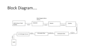
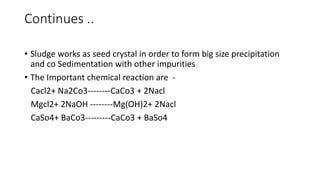
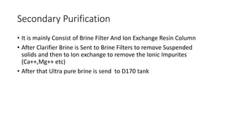
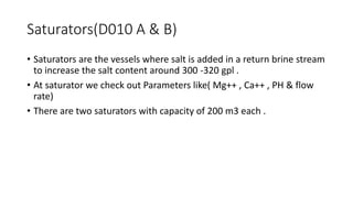
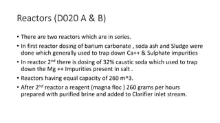
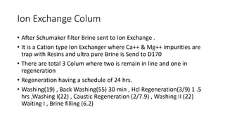
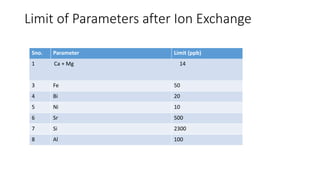
A Brief Presentation On
Brine House Section
Ashish Chauhan
Content
• Introduction
• Block Diagram representation of a process
• Process Description
• Brief Description of each process
Introduction
• It is a very first section of Process where Salt is Purified by mainly Two
type of Processes
• After Feeding through Feed Bucket (Z015 , Z016 ) First unit process is
Saturators where Return Brine form D080 added with Salt to enhance
its concentration
Primary Filtration (Reactors Dosing , Clarifiers , Anthracite Filter )
Secondary Filtration (Brine Filters , Ion Exchange )
Block Diagram….
Process Description
Primary Brine Purification process is composed of salt conveyor system
, saturator , Retention tanks , Clarifier , Clarified brine Tank and
associated Facilities.
The Purpose of this process is to re-saturate the return brine with the
raw salt and to remove the impurities present in it . The saturated raw
brine overflows from salt saturator and flows into reactor . Chemicals
such as barium carbonate , soda ash , and caustic soda plus sludge are
dose in consequent reactors , Calcium , magnesium and other
multivalent metals cations in raw brine react with these reactant
changed into Suspended solids ( caco3, mg(OH)2, Fe(OH)2 , baso4 etc )
with flocculant while pure brine taken from top clarifier .
Continues ..
• Sludge works as seed crystal in order to form big size precipitation
and co Sedimentation with other impurities
• The Important chemical reaction are -
Cacl2+ Na2Co3--------CaCo3 + 2Nacl
Mgcl2+ 2NaOH --------Mg(OH)2+ 2Nacl
CaSo4+ BaCo3---------CaCo3 + BaSo4
Secondary Purification
• It is mainly Consist of Brine Filter And Ion Exchange Resin Column
• After Clarifier Brine is Sent to Brine Filters to remove Suspended
solids and then to Ion exchange to remove the Ionic Impurites
(Ca++,Mg++ etc)
• After that Ultra pure brine is send to D170 tank
Salt Go down
• Salt Go down having total capacity of 3165 MT per day .
• Per day consumption of salt is roughly around 500 ton per day
• Main distributors are dev Salt , Ruby Salt , Asha etc.
• Salt analysis is the first step to check the salt purity which is done in
LAB.
Saturators(D010 A & B)
• Saturators are the vessels where salt is added in a return brine stream
to increase the salt content around 300 -320 gpl .
• At saturator we check out Parameters like( Mg++ , Ca++ , PH & flow
rate)
• There are two saturators with capacity of 200 m3 each .
Reactors (D020 A & B)
• There are two reactors which are in series.
• In first reactor dosing of barium carbonate , soda ash and Sludge were
done which generally used to trap down Ca++ & Sulphate impurities
• In reactor 2nd there is dosing of 32% caustic soda which used to trap
down the Mg ++ Impurities present in salt .
• Reactors having equal capacity of 260 m^3.
• After 2nd reactor a reagent (magna floc ) 260 grams per hours
prepared with purified brine and added to Clarifier inlet stream.
Clarifier ( A 132 A & B )
• Two clarifiers are there with capacity of 1800 m^3 & 1400 M^3 .
• Which is used to settle down the Suspended Solids at the bottom
.and clear liquid(Brine) is taken from the top . Turbidity is generally at
C/o is less than 5 NTU
• Other parameters like( Excess OH-- , Excess Co3--, PH , temperature ,
Chemical Dosage rate , Brine Concentration ) are monitors in a regular
hours
• According to which dosage of chemicals , floccule are added in a Brine
Clarifier ( Working Principle )
• Clarifiers are the settling tanks which is used to settle down & remove with the help of
mechanical mean sediment(waste Solids) settle down by sedimentation process .Floated particles
called scum and particle collected at bottom called sludge.
• Before clarifier inlet Flocculation reagent is added to clump the suspended particles & increase its
density so it settle down particles.
• Two dominant forces acting on the solids particles settle down in tank gravity and interaction
between particles.
• Feed enters from center and moves toward upward direction due to temperature gradient so
Particles settle down due to gravity .
• Baffles are used to reduce the turbulence at inlet by reducing the inlet velocity so settling occurs
in faster rate.
Anthracite filters (F040 A,B,C & D)
• These are filters arrange in series used trap down the suspended particles which
is not settle down in clarifier .
• Turbidity is the main parameter used to measure at inlet and outlet & which
should be Less than 1 NTU at outlet
• Three main operation is done filtration , Backwashing & then Bed Reset .
• Three Filters operates Automatically & D need to operate Manually
• A bed of Anthracite particles is there & Brine from D040 (clarifier Storage Tank )
enters and collected to D042 ( Anthracite storage tank) .
• Normal backwash is also comes from D042 and collected to D062 tank & Bed
Reset enters from Brine Inlet & collected to D042
Schumaker Filters ( F140 A & B)
• Two filters are in Series which is generally in series .
• It Consist of Carbon candles which covers with Alfa cello use layer
which used to trap down suspended particles .
• There are two condition when we required for precoating.
 If flow rate above 20000 .
Or Pressure Differential >2kg/cm^2.
Filter Brine is collected to D150 .
Ion Exchange Colum
• After Schumaker filter Brine sent to Ion Exchange .
• It is a Cation type Ion Exchanger where Ca++ & Mg++ impurities are
trap with Resins and ultra pure Brine is Send to D170
• There are total 3 Colum where two is remain in line and one in
regeneration
• Regeneration having a schedule of 24 hrs.
• Washing(19) , Back Washing(55) 30 min , Hcl Regeneration(3/9) 1 .5
hrs ,Washing I(22) , Caustic Regeneration (2/7.9) , Washing II (22)
Waiting I , Brine filling (6.2)
Limit of Parameters after Ion Exchange
Sno. Parameter Limit (ppb)
1 Ca + Mg 14
3 Fe 50
4 Bi 20
5 Ni 10
6 Sr 500
7 Si 2300
8 Al 100

Brine treatment Section

  • 1.
    A Brief PresentationOn Brine House Section Ashish Chauhan
  • 2.
    Content • Introduction • BlockDiagram representation of a process • Process Description • Brief Description of each process
  • 3.
    Introduction • It isa very first section of Process where Salt is Purified by mainly Two type of Processes • After Feeding through Feed Bucket (Z015 , Z016 ) First unit process is Saturators where Return Brine form D080 added with Salt to enhance its concentration Primary Filtration (Reactors Dosing , Clarifiers , Anthracite Filter ) Secondary Filtration (Brine Filters , Ion Exchange )
  • 4.
  • 5.
    Process Description Primary BrinePurification process is composed of salt conveyor system , saturator , Retention tanks , Clarifier , Clarified brine Tank and associated Facilities. The Purpose of this process is to re-saturate the return brine with the raw salt and to remove the impurities present in it . The saturated raw brine overflows from salt saturator and flows into reactor . Chemicals such as barium carbonate , soda ash , and caustic soda plus sludge are dose in consequent reactors , Calcium , magnesium and other multivalent metals cations in raw brine react with these reactant changed into Suspended solids ( caco3, mg(OH)2, Fe(OH)2 , baso4 etc ) with flocculant while pure brine taken from top clarifier .
  • 6.
    Continues .. • Sludgeworks as seed crystal in order to form big size precipitation and co Sedimentation with other impurities • The Important chemical reaction are - Cacl2+ Na2Co3--------CaCo3 + 2Nacl Mgcl2+ 2NaOH --------Mg(OH)2+ 2Nacl CaSo4+ BaCo3---------CaCo3 + BaSo4
  • 7.
    Secondary Purification • Itis mainly Consist of Brine Filter And Ion Exchange Resin Column • After Clarifier Brine is Sent to Brine Filters to remove Suspended solids and then to Ion exchange to remove the Ionic Impurites (Ca++,Mg++ etc) • After that Ultra pure brine is send to D170 tank
  • 8.
    Salt Go down •Salt Go down having total capacity of 3165 MT per day . • Per day consumption of salt is roughly around 500 ton per day • Main distributors are dev Salt , Ruby Salt , Asha etc. • Salt analysis is the first step to check the salt purity which is done in LAB.
  • 9.
    Saturators(D010 A &B) • Saturators are the vessels where salt is added in a return brine stream to increase the salt content around 300 -320 gpl . • At saturator we check out Parameters like( Mg++ , Ca++ , PH & flow rate) • There are two saturators with capacity of 200 m3 each .
  • 10.
    Reactors (D020 A& B) • There are two reactors which are in series. • In first reactor dosing of barium carbonate , soda ash and Sludge were done which generally used to trap down Ca++ & Sulphate impurities • In reactor 2nd there is dosing of 32% caustic soda which used to trap down the Mg ++ Impurities present in salt . • Reactors having equal capacity of 260 m^3. • After 2nd reactor a reagent (magna floc ) 260 grams per hours prepared with purified brine and added to Clarifier inlet stream.
  • 11.
    Clarifier ( A132 A & B ) • Two clarifiers are there with capacity of 1800 m^3 & 1400 M^3 . • Which is used to settle down the Suspended Solids at the bottom .and clear liquid(Brine) is taken from the top . Turbidity is generally at C/o is less than 5 NTU • Other parameters like( Excess OH-- , Excess Co3--, PH , temperature , Chemical Dosage rate , Brine Concentration ) are monitors in a regular hours • According to which dosage of chemicals , floccule are added in a Brine
  • 13.
    Clarifier ( WorkingPrinciple ) • Clarifiers are the settling tanks which is used to settle down & remove with the help of mechanical mean sediment(waste Solids) settle down by sedimentation process .Floated particles called scum and particle collected at bottom called sludge. • Before clarifier inlet Flocculation reagent is added to clump the suspended particles & increase its density so it settle down particles. • Two dominant forces acting on the solids particles settle down in tank gravity and interaction between particles. • Feed enters from center and moves toward upward direction due to temperature gradient so Particles settle down due to gravity . • Baffles are used to reduce the turbulence at inlet by reducing the inlet velocity so settling occurs in faster rate.
  • 14.
    Anthracite filters (F040A,B,C & D) • These are filters arrange in series used trap down the suspended particles which is not settle down in clarifier . • Turbidity is the main parameter used to measure at inlet and outlet & which should be Less than 1 NTU at outlet • Three main operation is done filtration , Backwashing & then Bed Reset . • Three Filters operates Automatically & D need to operate Manually • A bed of Anthracite particles is there & Brine from D040 (clarifier Storage Tank ) enters and collected to D042 ( Anthracite storage tank) . • Normal backwash is also comes from D042 and collected to D062 tank & Bed Reset enters from Brine Inlet & collected to D042
  • 15.
    Schumaker Filters (F140 A & B) • Two filters are in Series which is generally in series . • It Consist of Carbon candles which covers with Alfa cello use layer which used to trap down suspended particles . • There are two condition when we required for precoating.  If flow rate above 20000 . Or Pressure Differential >2kg/cm^2. Filter Brine is collected to D150 .
  • 16.
    Ion Exchange Colum •After Schumaker filter Brine sent to Ion Exchange . • It is a Cation type Ion Exchanger where Ca++ & Mg++ impurities are trap with Resins and ultra pure Brine is Send to D170 • There are total 3 Colum where two is remain in line and one in regeneration • Regeneration having a schedule of 24 hrs. • Washing(19) , Back Washing(55) 30 min , Hcl Regeneration(3/9) 1 .5 hrs ,Washing I(22) , Caustic Regeneration (2/7.9) , Washing II (22) Waiting I , Brine filling (6.2)
  • 17.
    Limit of Parametersafter Ion Exchange Sno. Parameter Limit (ppb) 1 Ca + Mg 14 3 Fe 50 4 Bi 20 5 Ni 10 6 Sr 500 7 Si 2300 8 Al 100