3. Dear Customers and Business Partners;
This year we celebrate the 20th
anniversary of our
firm Teknoklima, which we founded in 1995. We
continue our services which began with distributors-
hip activities in the air handling unit sector with a
structure encompassing 5 regional directorates, 10
partners, and 75 dealers within the framework of
our agreement with Samsung Electronics System Air
Conditioners.
Within 2014, we have decided to commence ma-
nufacturing in the system air conditioners sector
by combining our engineering infrastructure and
our accumulated know-how; and opened our first
manufacturing plant in Beylikdüzü, Istanbul with an
indoor area of 5000 m2
. We currently manufacture
air handling units (Dx and Water), packaged hygienic
operating room units, poolside air handling units, and
compact heat recovery units.
We have named our brand launched in 2014, which
we manufacture in conformance with all expectations
of the HVAC sector, and with a high quality approach
BOREAS after the mythological North Wind. We have
assigned particular significance to high quality stan-
dards in products. Our objective is to make sure that
our brand finds its deserved place not only in our own
country, but in a wide geographical region.
I thank all my esteemed colleagues, in our belief in
the dynamism we have brought about in the sector
with our brand, BOREAS.
Uğur Darcan
General Manager
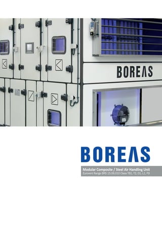
3BOREAS AIR HANDLING UNIT BOOK
4. AIR CONDITIONING 7
AIR CONDITIONING 8
Comfort Applications 8
Hygiene Applications 8
Process Applications 9
AIR CONDITIONING SYSTEMS 8
Centralized Systems 8
Stand-Alone Systems 9
AIR HANDLING UNIT 10
Ventilation 10
Cooling and Dehumidification 11
Heating 11
Heat Recovery Systems 11
Filtration 12
Humidification 12
Historical Development of Air Handling Unit Casings 13
THE BOREAS AIR HANDLING UNIT 15
PANEL STRUCTURE 16
FRAME STRUCTURE 16
THE ADVANTAGES 17
Investors 17
End Users 17
Design Offices and Consultants 18
Installers 18
OUR INNOVATIONS AND DIFFERENCES 19
Using Composite Material 19
Boreas Air Handling Unit Selection Software 20
Boreas Psychrometric Calculation Software 21
Magnelis®
Sheet Metal 22
OUR QUALITY CERTIFICATES 23
DESIGN SPECIFICATIONS OF BOREAS AIR HANDLING UNIT 25
FRAME STRUCTURE 28
PANEL STRUCTURE 29
MODULAR STRUCTURE 30
DIMENSION TABLES 31
CORROSION AND CORROSION RESISTANCE PROPERTIES 33
TECHNICAL SPECIFICATIONS OF BOREAS ACCORDING TO EN 1886 34
COMPONENTS OF BOREAS 37
FAN SELECTION 38
Information Required for Fan Selection 40
Fan Laws 40
Specific Fan Power – SFP 41
ErP (Energy Related Products) Directives for Fans 41
Electrical Motors 42
FAN SECTIONS 42
Centrifugal Fan Section 42
- Belt and Wheel System 43
- Vibration Insulating System 44
Plug Fan Section 46
Fan Series 47
COIL SECTIONS 48
Water Coils 48
Gas Coils 50
Coil Sections 50
Amount of Condensation And Drainage System 50
CONTENTS
4 BOREAS AIR HANDLING UNIT BOOK
5. HEAT RECOVERY SYSTEMS 52
Rotary Heat Recovery 52
Cleaning the Exhaust Air on the Fresh Air Line 54
Drive Unit 54
Fan Placement 54
Plate Type Heat Recovery 55
Free Cooling in Plate Type Heat Recovery 55
Condensation Control in Plate Type Heat Recovery 56
Freeze Control in Plate Type Heat Recovery 56
Run Around Type Heat Recovery 57
Free Cooling in Run Around Heat Recovery 57
Freeze Control in Run Around Heat Recovery 57
Condensation Control in Run Around Heat Recovery 57
Heat Pipe Heat Recovery 58
Comparison of Heat Recovery Systems 59
FILTER SYSTEMS 60
Influence of Filters on Energy Consumption 60
Filter Frame Leakage Class According to EN 1886 61
Panel Filter Section 62
Bag Filter Section 63
Active Carbon Filter Section 64
Metallic Filter Section 65
Multistage Filter Application in Air Handling Units 65
MIXING SECTIONS 66
Double Damper Mixing Section 67
Triple Damper Filter Section 68
ELECTRICAL HEATER 69
Electrical Heater Section 69
Safety Measures in the Electrical Heater Section 70
HUMIDIFICATION SYSTEMS 71
The Effects of Humidity on Comfort, Health, and the Environment 71
Steam Humidifier Section 72
Evaporative Wick Adiabatic Humidifier Section 73
High Pressure Humidification Section 75
ATTENUATING SYSTEMS 76
Sound Pressure and Power 76
Sound Pressure Range 77
Preventing Noise 77
Attenuator Section 79
ACCESSORIES 80
Sight Glass 80
UV (Ultraviolet) Lamp 80
Camera 80
Lighting 80
Access Door Safety Switch 81
Access Door Stopper 81
Water Coil Valve + Valve Motor 81
Panic Button 81
Repair and Maintenance Switch 81
Differential Pressure Switch 81
Damper Motor 81
Freeze-free Thermostat 82
Humidity and Temperature Sensor 82
Frequency Converter 82
Water Coil Connection Flange 82
Roofing Sheet and Hood 82
Active Attenuator 82
AUTOMATION SYSTEMS 83
Automation Equipment Used in the Air Handling Unit 84
Automation Scenarios in the Air Handling Unit 85
USEFUL INFORMATION 86
ISSUES THAT SHOULD BE TAKEN INTO CONSIDERATION WHILE SELECTING AHU 88
How to use the Psychrometric Chart 90
5BOREAS AIR HANDLING UNIT BOOK
8. Air conditioning is the process by which temperature, humidity, and
indoor air quality conditions are kept under control for the purposes
of comfort or industrial processes. Air conditioning applications can be
grouped under the three broad headings of Comfort Applications, Hygiene
Applications, and Process Applications.
Comfort Applications
Studies have shown that people exhibit the highest performance in living
and working spaces at 22°C. Performance increases by approximately
1% with each 0.6% change in ambient temperature. Therefore, air condi-
tioning is significant with respect to work performance and comfort of the
environment. Some examples of areas of application are:
• Residential and commercial buildings
• Hotels, industrial spaces,
• Vehicles, trains, and airplanes.
Hygiene Applications
These are applications where air conditioning processes needed for ma-
intaining hygienic conditions required for application areas with methods
and equipment that are in compliance with hygiene conditions. Some
examples are:
• Operating rooms and intensive care units
• Drug manufacturing facilities, Food industry manufacturing and sto-
rage facilities
• Electronic processes
Process Applications
These are applications implemented for ensuring the climate conditions
required by the process applied. Some examples are:
• Industrial environments
• Laboratories
• Cooking and food processing areas
• Textile factories
• Physical testing centers
• Data processing centers
• Operating rooms in hospitals
• Pharmaceutical plants.
Air conditioning system are principally divided in two groups, central
and stand-alone systems.
1- Central Systems;
They are further grouped in 5 subgroups, which are full air, full water,
VRF (variable refrigerant flow system), air-water, and air-VRF systems.
Full water systems are two and four pipe Fan Coil systems. Air - water
systems are achieved by adding fresh air to these systems. Similarly,
VRF systems are those where dozens of indoor units can be connected
to one outdoor unit, using a refrigerant gas such as R410A as coolant;
and air-VRF systems are achieved by adding fresh air to VRF systems.
2- Stand-alone Systems are divided in the following 3 groups:
1. Packaged Air Handling Units,
2. Split Air Handling Units,
3. Ducted Split Air Conditioners.
Central Full Air Air Conditioning Systems
These are systems where air is used as heat transfer fluid. The HVAC
equipment is placed centrally. Full air systems transfer air that has been
Air Conditioning
Air Conditioning
Systems
8 BOREAS AIR HANDLING UNIT BOOK
9. cooled and dehumidified to the conditioned room, providing sensible
and latent cooling; and transfer heated air to the conditioned room,
providing heating. Full air systems are capable of air filtration and supp-
lying fresh air.
Classification of Full Air Systems:
a) Fixed air flow
b) Variable air flow
c) Single duct
d) Multi-duct
e) Single zone
f) Multi zone
a) Fixed Air Single Duct Single Zone Systems
These are the simplest systems which serve a single zone, have fixed
air flow, and variable air discharge temperature. The temperature of air
blown into the space is automatically controlled.
b) Fixed Air Flow Mixed Air Systems
These systems comprise heating and cooling coils, fresh air and exha-
ust air mixture dampers, humidifier, aspirator, and fans.
c) VAV (Variable Air Volume) Systems
VAV systems have been developed particularly for multi-zone applicati-
ons and spaces with varying loads. The use of VAV systems is not opti-
mal in terms of fixed cooling load. In VAV systems, air flow is modulated
in the main supply fan equipped with frequency converter capacity
control in the main unit, and the air is transferred to VAV boxes and disc-
harge grilles in spaces. Air output in the air handling unit discharge is
fixed. The amount of air supplied to the room is changed via VAV boxes,
compensating for variations. VAV boxes balance room’s cooling load by
adjusting the amount of cold air supplied with the command it receives
from the room.
Central Fan Coil (All-Water) Systems
These are all water systems. Hot and cold water prepared in a center is
sent to fan-coil units distributed within the building. Hot water is gene-
rated in a boiler while the cold water is generated in a chiller. Fan-Coil
units include a fan and coil. The heated or cooled air is taken from the
room via the fan, passed over the coils, and returned to the room.
If cold water circulates within the coil, the system cools, and if hot water
circulates within it, the system heats. A pump is used for water circula-
tion. These systems are generally used in hotels, hospitals, and offices.
Fan-Coil units are placed in front of windows, in suspended ceilings,
below ceilings, or within the floor. There are 2 types of fan-coil systems:
1) 2 Pipe Systems (1 distribution, 1 collection pipe)
2) 4 Pipe Systems (2 distribution, 2 collection pipes)
Air-Water Mixed Air Handling Units
There is no ventilation in conventional fan-coil systems. These only pro-
vide heating and cooling. 2 applications are made in fan-coil systems to
make up for this lack.
1- Each fan-coil unit is provided with fresh air from the outdoor through
its own duct connection.
2- Having heat recovered, pre-conditioned and calculated by the au-
tomated system, fresh air is supplied to the environment by the air
handling unit system.
VRF-AirHandlingUnitGasPiping
VRFIndoorUnitGasPipingVRFIndoorUnit
VRFIndoorUnitGasPipingVRFIndoorUnit
5th
GenerationHeatRecoveryAirHandlingUnit
5th
GenerationHeatRecoveryAirHandlingUnit
5th
GenerationHeatRecoveryAirHandlingUnit
Chiller
Chiller
Boiler
Boiler
AirHandlingUnitFreshAirDuctwork
AirHandlingUnitFreshAirDuctwork
Chiller-AirHandlingUnitWaterPiping
Chiller-AirHandlingUnitWaterPiping
Boiler-AirHandlingUnitWaterPiping
Boiler-AirHandlingUnitWaterPiping
ChillerandBoiler–AirHandlingUnitWaterPiping
VAV
VAV
5th
GenerationHeatRecoveryAirHandlingUnit
AirHandlingUnitFreshAirDuctwork
AirHandlingUnitFreshAirDuctwork
VRF
VRF
9BOREAS AIR HANDLING UNIT BOOK
10. Air handling units are devices which can carry out air conditioning
processes such as ventilation, heating, cooling, humidification, de-
humidification, filtration, and heat recovery under automatic control.
Ventilation
The movement of air in the air handling unit is achieved with the aid of
fans. Fixed or variable air flow can be provided depending on the system
design.
Cooling and Dehumidification
Cooling is achieved via air to water or refrigerant to air (DX) heat
exchangers.
• Conditioned cold water required in the water system is generated by
the chiller and sent to the cooling exchanger in the air handling unit
with the aid of the pump. Warm air that is passes over the exchan-
ger, and is cooled by transferring its heat to the water with the help
of the exchanger.
• In the refrigerant system, the evaporator and expansion valve in the
air handling unit, or the condenser, compressor and gas installation
in the VRF outdoor unit or condenser/compressor section in com-
bination provide the required supply for cooling. The liquid phase
refrigerant that comes from the VRF or condender/compressor unit
undergoes pressure loss by passing through the expansion valve
Electrical Heater - Air Handling Unit Water Cooled Chiller - Air Handling Unit VRF- Air Handling Unit
Air Handling Unit
VRF (Variable Air Flow) Systems
VRD systems comprise a central condenser-compressor unit and
subsidiary indoor units. While advanced automation features enable
each of dozens of indoor units to be operated at different conditions of
comfort, the unit meets the demand for heating by operating as a heat
pump during the winter. Each indoor unit of 3 pipe systems of the energy
recovery type can operate independently in the cooling or heating mode
during the same season.
Air-VRF Mixed Air Handling Units
VRF systems do not include ventilation. These only provide heating and
cooling. 2 applications are made to make up for this lack.
1- A central duct air handling unit is used, which feeds fresh air into the
system. In these systems, fresh air that has been pre-conditioned and
subjected to heat recovery can also be humidified to the extent desired.
2- In spaces which require fresh air of low flow rate, the demand for
fresh air is met using compact ventilation units with heat recovery.
Water Cooling Tower
Water Cooled Chiller
Heat Recovery Air Handling Unit
Water Circulating Pump
Air Handling Unit Water Cooling Exchanger
VRF
AHU
Electronic Expansion Valve
VRF - Air Handling Unit Gas Line
Air Handling Unit Direct Expansion Cooling ExchangerAHU
Electrical
Heater
Thermistor (80°C)
High Temperaure Sensor
Air Flou Sensor-
Perforated Sheet
Metal
Cold Air
Heated Air
10 BOREAS AIR HANDLING UNIT BOOK
11. and evaporates by receiving the heat needed for evaporation from
the air passed over the evaporator. Air is cooled in this manner.
Heating
Heating can be achieved in air handling units via water, electrical, refri-
gerant (heat pump), natural gas (open and closed combustion chamber)
systems.
• Hot water required in the water system is generated in the boiler and
sent to the water heating exchanger in the air handling unit with the
aid of the pump.
• In the electrical heating system, air is heated with the aid of resistan-
ces placed within the air handling unit.
• In the refrigerant system, the condenser/compressor unit or VRF
outdoor unit integrated in the air handling unit operate in the heat
pump mode, using the heat exchanger within the air handling unit as
a condenser. Thus, it provides heating by transferring the waste heat
generated in the cooling cycle to the air.
• In the natural gas system, heat energy generated by the direct or
indirect combustion unit is transferred to the air passed over it, incre-
asing the temperature of the air.
Heat Recovery Systems
Heat recovery equipment is indispensable in designing air conditioning
systems with a minimum energy expenditure. Heat recovery systems are
divided in two main groups as Recuperative and Regenerative Systems.
Recuperative systems
• Plate Type Heat Recovery is achieved by passing the conditioned return
air and fresh air over an exchanger, in such a way that they do not mix.
Regenerative systems
• Run Around Heat Recovery is achieved by passing the conditioned
return air and fresh air over two separate exchangers containing water.
Water circulation is achieved in the system with the aid of a pump.
• Heat Pipe Heat Recovery utilizes the principle of evaporation and
condensation of the refrigerant within a single two section exchanger
placed on the conditioned exhaust air line and on the fresh air line.
• In the Rotary Drum Heat Recovery system, heat recovery takes place
between fresh air and indoor air that are at different temperatures and
humidity levels with the help of a rotary type heat exchanger. It enables
the transfer of only sensible heat, or of both sensible and latent heat.
Boiler - Air Handling UnitVRF- Air Handling Unit Burner - Air Handling Unit
AHU
Natural Gas Direct Combustion Unit
Control Panel
Boiler
AHU
Cold Air
Heated Air
Cold Air
Heated Air
Hot Water Circulating Pump
Air Handling Unit Water Heating Exchanger
VRF
Electronic Expansion Valve
AHU
VRF - Air Handling Unit Gas Line
Direct Expansion Heating Exchanger
Cold Air
Heated Air
11BOREAS AIR HANDLING UNIT BOOK
12. Filtration
Since air handling units facilitate operation with a high percentage of fresh air,
filtration is highly significant for the protection of equipment within the unit, as
well as the hygiene conditions of the conditioned environment. All filters of the G
(gross filter), and F (fine filter) series filters can be used with filter units placed
within the air handling unit.
Humidification
2 different humidification systems can be applied in the air handling unit, which
are adiabatic humidification and isothermal (steam) humidification.
1. In adiabatic humidification, thermal energy for the vaporization of water is not
supplied externally, it is applied in two different ways:
- Vaporization over moistened medium
Porous media capable of absorbing water, placed within the air handling unit
is moistened with water, forming a moist surface. Air passing over this surface
acquires moisture by evaporating the water.
- High pressure water spray
Nozzles placed within the air handling unit cause water pressurized up to 100
bar to be converted to mist. These water particles mix into the air, providing
humidification.
2. Isothermal (steam) humidification requires external heat energy; steam that
is generated in the steam generator integrated into the air handling unit frame
or that is ready in the plant is mixed into the air within the air handling unit with
the aid of diffusers, providing humidification.
Steam
Humidification
Humidification via Moistened
Medium
Humidification via High
Pressure Spray
12 BOREAS AIR HANDLING UNIT BOOK
13. 1st
Generation air handling units
Were manufactured with a generalized frame and welded connections. The
panel structure was single walled, not insulated and was manufactured from
DKP sheet metal. This led to a product with long manufacturing periods, low
useful life, with high energy losses.
2nd
Generation air handling units
Transitioned to another design where the panel structure was double walled,
insulated, manufactured of galvanized or painted sheets, with an Aluminum
frame. Condensation that occurred in the housing at critical climate conditi-
ons due to thermal bridging upset the conditions of comfort and shortened
the unit’s useful life.
3rd
Generation air handling units
Were designed wit Aluminum frames and reduce thermal bridging to comply
with the light structure concept and aesthetics in parallel with the develop-
ments in structural design. The panel structure was double walled, and ma-
nufactured with insulated painted sheet metal. However, due to the structural
properties of Aluminum, flexions and dissolutions occurred at connection po-
ints during transport and assembly, which led to problems related to housing
strength. Plastic based thermal barriers began to be used to remove thermal
bridging via frame profiles, but this led to problems related to mechanical
strength.
4th
Generation air handling units
Transitioned to a design with a steel
housing, which allowed assembly not
with welding, but with specialized
fittings. In this way, problems with
welded housing design which caused
problems in 1st and 2nd generation
air handling units were eliminated as
well as structural problems encoun-
tered in air handling units with Alu-
minum housing. Designs were intro-
duced where contact between metal
parts in panel structures was partially
prevented. However a thermal bridge-
free unit could not be achieved due to
the high thermal transfer coefficient
of the steel frame.
The 5th
Generation air handling unit
The first objective in designing BOREAS, was to create a product that would
eliminate all negative aspects and carry all positive aspects of the previous
generation air handling units. Consequently, a frame structure with minimal
energy losses, capable of trouble free operation in critical climate conditions,
with high resistance values against varying loads that may be exerted on the
housing structure, with higher structural values than steel frame housing
yet lighter than Aluminum housing were determined as design inputs for the
5th Generation Air Handling Unit BOREAS, and the design of BOREAS was
completed.
Historical
Development of
Air Handling Unit
Housing
Technical
Properties
1st
Generation
2nd
Generation
3rd
Generation
4th
Generation
5th
Generation
Thermal
Bridging
Thermal
Bridging
Thermal
Bridging
Reduced
Thermal
Bridging
Reduced
Thermal
Bridging
Thermal
Bridge-free
Panel Struc-
ture
Single Wall Double Wall Double Wall Double Wall Double Wall
Insulation None Rock Wool Rock Wool
Rock Wool +
Polyuret-
hane
Rock Wool
+ Polyuret-
hane
Sheet Metal
DKP +
Painted
Galvanized
+ Painted
Galvanized
+ Painted
Galvanized
+ Painted
Magnelis +
Painted
Frame Struc-
ture
Welded Aluminum Aluminum Steel
Composite
+ Steel
Corrosion
Resistance
Low Low Medium Medium High
13BOREAS AIR HANDLING UNIT BOOK
16. Panel Structure
Frame Structure
• Provides trouble-free performance, and hygienic and extended life
cycle in critical climate conditions by using MAGNELIS®
sheet, which
has 5 times higher corrosion resistance than standard galvanized
sheet.
• PVC profile comprising the panel frame acts as a heat barrier between
the inner and outer sheet metal surfaces. The porous nature of the
PVC profile enhances both the structural strength and heat insulation
as well.
• Concave profiles on the panel joint interface on the inside allow for-
mation of smooth edges that can be cleaned. Thus, details that have
hygienic properties can be obtained even in a comfort air handling
unit. This property prevents thermal bridging that can be formed thro-
ugh the frame profile.
• The typical insulation is provided by using 50 mm rock wool with 70
kg/m³ density. An optional insulation by using 50 mm polyurethane
materials with 40 kg/m³ applied through injection is available as well.
Aframe that has higher mechanical strength than that of a steel
profile, and that is lighter than an aluminum frame structure is achi-
eved through using rectangular profiles manufactured from composite
material. Due to the fact that the composite material has a much lower
heat transfer factor when compared to steel and aluminum, it ensures a
TB1 Thermal Bridge Free class according to EN 1886 by preventing the
formation of thermal bridges at the joints between the frame and the
panel, and between the fittings.
16 BOREAS AIR HANDLING UNIT BOOK
17. The Advantages
Investors
With its innovative composite frame design, BOREAS Air Handling Units
are manufactured by using components that are resistant to extreme
operating conditions, long lasting, and have world-class certifications.
The results of BOREAS at the EN 1886 certification tests which can only
be achieved by high-end air handling units ensure the performance it
guarantees for years to come. Its advanced selection software enab-
les users to select the products that have the best performance/price
ratio. BOREAS achieves lowering the energy leaks from the casing of an air
handling unit below the acceptable limits by delivering L1 (< 0.15 l x s-1
x m-2
)
casing air leakage class, TB1 (0.75 ≤ kb
< 1.00) thermal bridging class,
and T2 (0.5 < U ≤ 1) thermal transmittance class.
End Users
Delivering complete and continuous multi-stage filtering, heating,
cooling, humidification, dehumidification and heat recovery through
automated controls, Boreas Air Handling Unit provides highly efficient
air conditioning that does not compromise on hygiene in comfort appli-
cations, as well as ventilation for living spaces.
• Thanks to its access doors that enable easy operating and mainte-
nance, every corner of the unit can be reached easily.
• Inner edges and corners are rounded to prevent accumulation of dirt.
Maintenance costs are lowered by providing easy service and main-
tenance conditions.
The unit has a high level of energy efficiency, and the factors delivering
this are as follows:
• Using highly energy efficient components;
• Very low, if any, loss of energy due to its L1 air leakage class, T2
and TB1 casing thermal transmittance and thermal bridge classes
respectively.
• Design specifications that have low internal resistance.
Extended life cycle that requires low maintenance is achieved by using
Magnelis® sheet metal and composite materials. The filter frame with
compression mechanism provides easy service.
TECHNICAL SPECIFICATIONS ACCORDING TO EN 1886:2007
Mechanical Strength
(mm x m-1
)
D1 D2 D3
4 10 >10
Casing Air Leakage
(l x sˉ1
x mˉ2
)
L1 (f400) L2 (f400) L3 (f400)
0.15 0.44 1,32
L1 (f700) L2 (f700) L3 (f700)
0.22 0.63 1,90
Filter Bypass Leakage
(%k)
F9 F8 F7 M6 G1-M5
0.5 1 2 4 6
Thermal Transmittance
(W x mˉ2
x Kˉ1
)
T1 T2 T3 T4 T5
U < 0,5 0.5 < U ≤ 1.0 1.0 < U ≤ 1.4 1.4 < U ≤ 2.0 2.0 < U
Thermal Bridging
TB1 TB2 TB3 TB4 TB5
0.75 < kb
< 1.00 0.60 ≤ kb
< 0.75 0.45 ≤ kb
< 0.60 0.30 ≤ kb
< 0.45 kb
< 0.3
LIFETIME COST AN AIR HANDLING UNIT
Maintenance Maintenance
0,07
Investment Investment
0,13
Energy
Consumption
Energy Consuption
0,80
17BOREAS AIR HANDLING UNIT BOOK
18. Design Offices and Consultants
Offering 40 different models that can meet a wide range of demand
between 2,000 m3
/h and 100,000 m3
/h, Boreas Air Handling Unit can
easily and rapidly be sized in various dimensions thanks to its modular
nature. It enables different types of heating, cooling, humidification,
dehumidification, heat recovery and filtering applications through
wide variety of components. BOREAS meets various specifications for
different using and operating conditions with its D1 (4 mm x m-1
) mec-
hanical strength class, L1 (< 0.15 l x s-1
x m-2
) casing air leakage class,
TB1 (0.75 ≤ kb
< 1.00) thermal bridging class, and T2 (0.5 < U ≤ 1) ther-
mal transmittance class. With its T2 thermal transmittance value and
TB1 thermal bridging value in particular, it is suitable for extremely high
and extremely low temperature climate conditions.
Its unique web-based air handling unit selection software enables
easy, fast and reliable product design and selection, as well as delive-
ring detailed reports and drawing printouts in .dxf format. It meets all
mandatory requirements for a selection software according to Eurovent
OM-5. Boreas Licensed Psyhometric Chart and Analysis Software facili-
tate calculations and design.
Installers
Multi-purpose handling rings and forklift fork holes provided for stand
designs of all models allow the units to be moved horizontally and verti-
cally with ease at construction sites. With the specially designed section
assembly method, sections of the air handling unit can be assembled
easily and rapidly even on uneven surfaces. Each section of the unit has
its own tag to make it easier to assemble.
18 BOREAS AIR HANDLING UNIT BOOK
19. Using Composite Material
Composite materials are made from two or more materials that, on
their own, are not suitable for the desired outcome, by combining them
physically and in macro design under certain conditions to deliver the
expected properties.
Composite materials contain a fibre material as a core, and a matrix
material composing the larger volume covers that core. Of these two
material groups, the fibre constitutes the strength and load carrying
properties, whereas the matrix material prevents crack propagation that
might occur during transition to plastic deformation and delays breaking
of the composite material. Another purpose of the material used as mat-
rix 11 is to keep the fibre materials together under load and distribute
the load between the fibres homogeneously.
The fact that the composite materials have low specific gravity provides
a huge advantage for them in light constructions. Additionally, the fact
that they are corrosion resistant and provide heat, sound and electrical
insulation, gives fibre reinforced composite materials an edge for rele-
vant applications.
Among these main advantages are:
• High rise mechanical strength
• Easy formability
• Electrical properties (very good insulation or conductivity)
• Corrosion and chemical resistance
• Heat insulation and fire resistance
• Vibration absorption
The fact that the composite materials are widely used in all aspects of
life and that the abovementioned properties are also expected from the
materials that frame structures are made of inspired us to combine them
in BOREAS. Thus, composite materials were used in BOREAS to provide
a frame structure that delivers both insulation and strength.
Benefits of Air Handling Units Manufactured From Composite
Material
The BOREAS air handling unit manufactured by using composite profiles
are differentiated from 4th
generation steel-framed units and 3rd genera-
tion aluminum-framed units thanks to its properties listed below.
• Vibrations derived from the moving parts inside the air handling unit
are transferred to the floor minimally thanks to the frame structure
of the AHU manufactured from composite material that has vibration
absorption property.
• Due to the fact that the composite profile has a high yield point, per-
manent deformation of the frame structure of the unit under variable
loads is prevented during moving, assembly and operation.
• Corrosion is prevented on the frame structure manufactured from
composite material. Thus, compared with the aluminum and steel
framed air handling units, the unit operates smoothly under extreme
climate conditions and the ambient conditions that might result in
corrosion.
• Thermal bridging property, the key criterion in loss of energy and sur-
face condensation, is provided at the highest level thanks to the fact
that the composite material has very low thermal transmittance factor
Our Innovations
And Differences
19BOREAS AIR HANDLING UNIT BOOK
20. as compared to aluminum and steel.
• Composite material has a high level of fatigue resistance, therefore
it ensures the frame structure to have a longer life cycle in terms of
mechanical properties than those of the aluminum and steel-framed
air handling units.
• The technical properties of the frame structure manufactured from
composite profile are superior to the aluminum and steel-framed air
handling units, and this gives a lighter weight than those two. This, in
result, lowers the overall weight of the air handling unit and creates a
much lower load for the structure.
BOREAS Air Handling Unit Selection Software is a Windows-based
selection tool that meets Eurovent requirements, access the data-
base over the Internet, has user friendly interfaces, defines the product
completely, can select the products from various manufacturers of air
handling unit components, can deliver 3-surface-appearance printouts
in .dxf file format, can display the price of the product you have designed
and selected, and can produce complete selection outputs as per Euro-
vent software requirements.
By using Boreas Air Handling Unit Selection Software, you can:
• produce air handling unit design, selection, drawing printouts in .dxf
file format and technical data output for a wide range of flow rate and
capacity intervals within modular sizes;
• access the updates instantaneously upon the improvements on the
selection software;
• choose among the latest approved .dll files from domestic and foreign
manufacturers for fans, batteries, and heat recovery exchangers;
Boreas
Air Handling Unit
Selection Software
20 BOREAS AIR HANDLING UNIT BOOK
21. You can perform all of the calculations required for your project, store
and print them with the BOREAS licensed Psychrometric Calculation
Software.
With the BOREAS Psychrometric Calculation Software you can:
• calculate all air conditioning
processes;
• select climate conditions for count-
ries and regions;
• calculate the evaporation amounts
in pool sites;
• calculate and design the cross sec-
tion of the air duct;
• use either IP or SI units;
• prepare a report containing dotted Psychrometric charts, process flow
charts and the thermal values for the dots on the chart;
• perform calculations for drum type and plate type heat recovery systems.
Boreas
Psychrometric
Calculation
Software
• obtain detailed and reliable technical data printouts and all the
technical data for the air handling unit you have selected in .pdf file
format;
• design the unit in minimum size and at the lowest cost by dynamically
changing the length of fans, batteries, heat recovery units and filter
sections within the modular sizes and optimizing the dimensions.
• due to the fact that it is a custom software for BOREAS Air Handling
Units, ensure that the designed and selected products are the same
with the manufactured and delivered products.
21BOREAS AIR HANDLING UNIT BOOK
22. Magnelis®
Sheet Metal
Magnelis® is manufactured at a traditional industrial hot dip gal-
vanized line, however it is dipped into a molten zinc bath with a
unique metallic chemical compound containing 3.5% aluminum and 3%
magnesium. 3% magnesium covers the entire surface with a smooth
and durable layer, and provides much better protection against corro-
sion in comparison with coatings containing lower magnesium. Since it
extends the life cycle of the product, it is important for the air handling
units which are operated under corrosive ambient conditions.
A high corrosion resistance is provided for BOREAS Air Handling Units, on
demand, by using Magnelis® sheet metal for inner and outer panel she-
ets and internal parts. Thanks to this property, the unit can be operated
trouble-free under the ambient conditions that have high humidity and
cause corrosion. Through high corrosion resistance, metal parts require
minimum maintenance and hygienic requirements are met for the metal
parts that have contact with air.
Anti-corrosive Properties of Products
HDG ZN Galfan Aluzinc Magnelis
In an environment containing chloride
(swimming pool)
Baseline + +++
In an environment containing ammonium (barn,
farm, greenhouse)
Baseline + = ++
In an environment containing SO2 (industrial
acidic environment)
Baseline + +
Temporary protection (transport, storage) Baseline + +++ ++
Edge protection Baseline + - +++
Corrosion on a deformed part Baseline + - ++
Weight Loss in the Toughest Conditions
22 BOREAS AIR HANDLING UNIT BOOK
23. Hygiene Certification
Boreas Air Handling Unit hygiene version tes-
ted by TÜV-SÜD according to VDI 6022 and
DIN 1946-4 standards. As a result of tests
performed, both the product structural featu-
res as well as the leakage class and thermal
bridging class has been shown to meet the
both standards required. Important properties
of the BRS-H encoded hygiene version are all
kinds of measures taken against corrosion
on internal structure and components, thanks to it’s smooth surfaces
cleaning is very easy to perform and it can be controlled in a sustainable
manner.
EAC Declaration
Declaration of the EAC Customs Union is the
name of the certificate that is prevailing at
the Eurasian Custom Union. The member co-
untries of the EAC Customs Union are Russia,
Belarus, Kazakhstan, Armenia and Kyrgyzstan.
Quality
Certifications
ISO 9001
In order to have its processes monitored
and improvable within the scope of total
quality approach, Tekno Klima awarded its
ISO 9001 certificate in 2013. ISO 9001 is
a management system implemented on
national and international levels to ensure
improvement on the organization’s sense of
quality, increase efficiency and market share,
an efficient management, decrease costs,
improve employee satisfaction, improve in-
ternal communications, ensure an extensive
monitoring and control in all activities, lower
the number of returns, decrease customer complaints, and increase
customer satisfaction.
Eurovent Certification
The BOREAS Air Handling Unit
is Eurovent Certified as Mecha-
nical Strength Class D1, Casing
Air Leakage Class L1, Thermal
Transmittance Class T2, Thermal
Bridging Class TB1, and Filter Bypass Leakage Class F9 according to
the results of tests performed in accordance with EN 1886. Eurovent
Certification documents the technical specifications and performance of
air conditioning and cooling products within the framework of European
standards. Therefore two different Eurovent certified products need not
have the same mechanical performance specifications; tests carried out
according to EN 1886 can yield various results between manufacturers
and products, and the results are published on the Eurovent website.
Certificate of Assessment
TEKNOKLIMA SAN. VE TIC. LTD. STI.
Istiklal Mahallesi Ataturk Caddesi No :25 Kirac / Esenyurt / Istanbul
EQA hereby grants to the above company
whose Quality Management System is in conformance with
ISO 9001:2008
Scope
Air Conditioning Plant, Ventilation Plant, Heat Recovery Unit
Production , Sales and Service
Registration No. QA140480
First issued on 22 August, 2014
This certificate is valid until 21 August, 2017
Further clarifications regarding the scope of this certificate and the applicability of ISO 9001:2008 requirements may be obtained by consulting EQA
#903, 9F, Byucksan Digital Valley 7-Cha, #170-13, Guro-dong, Seoul, Korea, 152-742 / URL:www.eqaworld.com
23BOREAS AIR HANDLING UNIT BOOK
26. Required flow rate and
pressure are supplied by
low noise and high effici-
ency fans and motors
Water systems or DX
coolers and heaters are
selected from Eurovent
certified products to
provide the best perfor-
mance.
Easy monitoring through
rectangular and wide sight
glasses and LED lighting
F9 leakage class filter as-
sembly and all types of filter
application in G3-F9 range
Outer walls of the double walled,
thermal bridge free, 50 mm
rock wool insulated panels are
manufactured from 1-mm-thick
galvanized and painted sheet
metal, and the inner walls are
0.8 mm galvanized or, on de-
mand, stainless sheet metal.
56
9
1
2
5 6 7
1
2
40 models are available with air flow capa-
cities of 2,000 m3
/h and 100,000 m3
/h to
meet a wide range of demand. The unit has a
reduced field wiring through flexible automa-
ted control solution and is compatible with all
common communication protocols.
26 BOREAS AIR HANDLING UNIT BOOK
27. Low grid resistance hid-
den gear driven “Anodized”
aluminum dampers
150-mm-high stands
with forklift openings
for moving also have
eye bolts to be carri-
ed with cranes
Boreas air handling
units are manufac-
tured by automated
systems to ensure,
control and maintain
comfort requirements
Metal casting door hinges that
allow adjusting in three axes
and locked door handles work
without a risk of corrosion bet-
ween the temperature range of
-40°C and +80°C.
Superior energy
efficiency through high
efficient heat recovery
aplications
8 9
3
10
4
Inner edges and corners are rounded to pre-
vent accumulation of dirt and manufactured
to meet easy assembly, maintenance and
cleaning requirements. Suitable for hygienic
applications in places such as hospitals, la-
boratories and clean rooms.
7
4
10
8
3
27BOREAS AIR HANDLING UNIT BOOK
28. In addition to financial implications of thermal bridging, what is really
important condensation of the moisture content of the air on cold sur-
faces. Condensation causes growth of micro organisms on wet surfaces,
consequently leads to health issues and shortens the lifetime of the unit
due to corrosion. Furthermore, the joints on the inner walls of the panels
on the adjacent surfaces of similar products cause heat leakages, and
they also allow dirt accumulation and enable micro organisms to grow,
both damaging hygienic conditions. There are efforts to cover such
spaces with mastic application but the quality of this work depends on
the skill and experience of the person performing the application, this
consequently results in hygienic issues.
To eliminate the problems experienced in the 3rd
and 4th
generation air
handling units we have mentioned above, an innovative approach has
been applied in the design of BOREAS air handling unit. The frame struc-
ture can be made of composite material optionally, thus achieving a ligh-
ter, thermal bridge free structure and high mechanical properties. The
panel structure composed of frames that were manufactured from PVC
profiles provide a thermal bridge free unit. Thanks to the rounded angle
seals used on the panel joints on inner walls, a structure that is easier to
clean and prevents dirt accumulation is achieved, notwithstanding the
skill and experience of the installer.
Boreas Air Handling Unit is composed of rectangular profiles made
out of 2-mm-thick steel material in 30 x 30 mm and 30 x 60 mm
size, and the corner and mullion joints that keep them together. BOREAS
Air Handling Unit has the highest D1 class according to EN 1886 Mec-
hanical Strength Test due to its usage of steel frame which has greater
mechanical properties than aluminum framed structures. As an optional
material, composite frames with much lower thermal transmittance fac-
tor than aluminum and steel profiles provide a heat insulation and ensu-
re a completely thermal bridge free frame structure.Composite profiles
with much lower thermal transmittance factor than aluminum and steel
profiles provide a natural heat insulation and ensure a completely ther-
mal bridge free frame structure. Continuous base frame design along
Frame Structure
28 BOREAS AIR HANDLING UNIT BOOK
29. the section edges was designed to transfer the weight of the sections
to the floor as a distributed load. 150-mm-high base frame structure is
standard, and contains fork holes for forklift and circular holes to allow
sections to be moved horizontally and vertically at construction sites. A
very strong thick EPP strip on relevant surfaces is used to prevent ther-
mal bridging between the base frame and the section frame structure.
Panel Structure
Panel structure which forms the casing of the air handling unit is the
most and effective equipment that affects the overall mechanical
performance of the unit. The panel structure of BOREAS is designed to
prevent thermal bridging between internal and external environment.
The contact between inner and outer surface sheet metals that are
mounted on the panel structure made up of PVC-based panel profiles is
completely prevented, thus providing thermal bridge free structure. Rigid
panel structure contributes greatly to its L1 class in Casing Air Leakage
Tests.
Typically, 50 mm rock wool in 70 kg/m3
density is used as panel insula-
tion material. With its PVC frame structure and standard insulation, its
Thermal Transmittance Class is T2 according to EN 1886. This class can
be upgraded to T1 by using optional Polyurethane insulation material.
Connecting screws that are used to connect panels to the frame structu-
re are hidden on the outer sheet metal, and provides a smooth, aesthetic
view on the outside. Screw caps on the screw heads prevent contact with
the external environment to avoid corrosion and thermal bridging.
PVC profiles with an operating range of -40 °C / +80 °C are manufactu-
red to offer high resistance against the effects of UV radiation. Trouble-
free operation is provided in extreme climate conditions by optionally
using highly corrosion resistant Magnelis®
sheet metal. Panel sheet
metals which, as a standard, is 0.8 mm thick on the inside and 1.0 mm
thick on the outside can optionally be applied in 0.8 and 1.2 mm thick-
ness, respectively. Custom manufactured EPDM-based porous seals
with low thermal transmittance factor are used on the joints of panels
and profiles.
29BOREAS AIR HANDLING UNIT BOOK
32. Modular Structure
SmartPack
The dimensions of BOREAS’s modular structure have been determi-
ned on the basis of standard filter measurements according to EN
775. In this way, the suitable cross section for filtration is achieved in air
handling units operating with high percentages of fresh air, and filter sur-
face areas can be used fully. Enclosed areas that may disrupt the lines
of air flow have been avoided in the cross section of air flow, eliminating
extra internal losses. This leads to reduced internal pressure losses and
reduced energy requirements for fan drive. For the same reason, by-pass
sealing is measured as F9, the highest level. The module measurement
has been determined as 102 mm, 1/6th
of the full scale filter. This makes
it possible to design air handling units with smaller steps.
SmartPack has been designed particularly to eliminate problems of
transport within the building and to reduce high transport costs at
long distances. The method determined for SmartPack is to make a full
inventory of all parts as intermediate products, package them in a way
that will be convenient for assembly, and assemble the unit on site with
trained technical teams.
The weakness of fittings is an issue in the most commonly used met-
hod where the unit is transported to the field after assembly and di-
sassembly in the factory. In another method, packages that contain a
great number of components are shipped without any assembly and the
assembly is carried out from scratch on site. In this case project errors
emerge on site and the solutions applied lead to loss of time and quality.
When the assembly is carried out fully in remote sites, the experience of
local workers, technical drawings, and assembly guides are insufficient.
In the SmartPack application, all designs and assemblies specific to the
project are made in advance in a computer environment, assembly of
intermediate products in accordance with the project is completed in the
factory environment, and shipped in packages that do not contain empty
spaces. Assemblies that are completed in advance in a 3D computer
environment allows on site assemblies monitored by a supervisor to be
completed in full and with no errors.
102 mm module length
Filter
FilterFilter
32 BOREAS AIR HANDLING UNIT BOOK
33. Air handling units are devices which carry out the ventilation and air
conditioning processes that are needed for providing the conditions
needed in living spaces in general. The maintenance of comfort and
hygiene conditions of the environment is the most significant criterion
while performing these functions. Wet surfaces that may occur within air
handling units create areas that are amenable for the growth of micro
organisms. It is of critical importance for these areas to be kept under
control, and brought to special conditions that do not permit the growth
of micro organisms. These wet spaces prepare the ground for corrosion
as well as the growth of micro organisms. This will shorten the unit’s
useful life, and prevent it from carrying out its functions fully.
In technical classifications determined for air handling units in EN 1886,
the most significant criterion in the creation of uncontrolled wet surfaces
is the thermal bridging class. The classification which determines the
magnitude of the thermal bridge in the EN 1886 standard ranges from
TB1 to TB5. On this scale, TB1 denotes the best case of the least thermal
bridging, while TB5 denotes the worst case of the most thermal bridging.
In the following example, the values for points where condensation be-
gins in summer conditions are provided in terms of TB value. BOREAS
which has a TB1 thermal bridging class minimises uncontrolled wet
spaces even in extreme climate conditions. It also offers high corrosion
resistance due to its highly corrosion resistant composite profile carcase
structure and the use of Magnelis® sheet metal. With these properties,
it ensured the conditions of comfort and hygiene needed continuously
and for an extended period, even in extreme climate conditions.
Corrosion
and Corrosion
Resistance
Properties
BOREAS which has a TB1 thermal bridging class does not permit the cre-
ation of uncontrolled wet spaces even in extreme climate conditions. It
achieves the highest class of thermal bridging and corrosion resistance
due to its highly corrosion resistant composite profile carcase structure
and the use of Magnelis® sheet metal. With these properties, it ensured
the conditions of comfort and hygiene needed continuously and for an
extended period, even in extreme climate conditions.
Summer Condition Winter Condition
33BOREAS AIR HANDLING UNIT BOOK
34. 2. Casing Air Leakage Class: L1
These are tests where the amount of possible air leakage from the
air handling unit casing under 400 Pa negative and 700 Pa positive
pressure
3. Filter Bypass Leakage Class: F9
Classification is made on the basis of the percentage of the air flow
passing unfiltered from the air handling unit filter frame under 400 Pa
positive pressure to total air flow.
1. Mechanical Strength: D1
The amount of deflection of the air handling unit frame is measured on
the Model Box under a pressure of ±1000 Pa is measured, and the air
handling unit is checked for permanent deformation under a pressure
of ±25000 Pa.
Technical
Specifications
of the Boreas AHU
According to
EN 1886
Casing Class
Maximum
Displacement
(mm/m)
D1 4
D2 10
D3 10 <
Casing Air Leakage
Class
Max. Air Leakage Percentage
f-400
(l x s-1
x m-2
)
Max. Air Leakage Percentage
f700
(l x s-1
x m-2
)
L1 0,15 0,22
L2 0,44 0,63
L3 1,32 1,9
Filter Class G1-M5 M6 F7 F8 F9
Max. Filter Leakage
Percentage %k
6 4 2 1 0,5
𝑞𝐿𝑡
=𝑞𝐿
+ 𝑞𝐿𝑓
𝑞𝐿𝑡
: Total Air Leakage
𝑞𝐿
: Casing Air Leakage
𝑞𝐿𝑓
: Air Leakage between the Filter Frame and Casing
1. Leakage Measurement Device
2. Surface of Entry
3. Closed Filter Surface
4. Filter Section
5. Casing
1. Leakage Measurement Device
2. Surface of Entry
3. Fully Closed Filter Surface
4. Filter Section
5. Casing
34 BOREAS AIR HANDLING UNIT BOOK
35. 4. Thermal Transmittance Class: T2
This is the test and classification for determining the thermal trans-
mittance of the air handling unit casing and panel structure. Tests are
carried out by maintaining a temperature difference of 20 K between the
air handling unit interior and exterior, and a 0.1 m/s air velocity over the
exterior surface.
5. Thermal Bridging Class: TB1
This is a test which determines and classifies thermal bridges that may
occur between the interior and exterior environment of the air handling
unit casing. The calculation is based on those points with the highest
temperature on the exterior surface where the temperature difference
between the internal and external environment is 20 K. A high class
indicates a low condensation risk on the air handling unit casing while a
low class indicates a high condensation risk.
Mechanical
Strentgh
(mm x mˉ¹)
D1 D2 D3
4 10 >10
Casing Air
Leakage
(l x sˉ¹ x mˉ²)
L1 (f400) L2 (f400) L3 (f400)
0,15 0,44 1,32
L1 (f700) L2 (f700) L3 (f700)
0,22 0,63 1,90
Filter Bypass
Leakage
(%k)
F9 F8 F7 M6 G1-M5
0,5 1 2 4 6
Thermal
Transmittance
(W x mˉ² x Kˉ¹)
T1 T2 T3 T4 T5
U < 0,5 0,5 < U ≤ 1,0 1,0 < U ≤ 1,4 1,4 < U ≤ 2,0 2,0 < U
Thermal Bridging
TB1 TB2 TB3 TB4 TB5
0,75 < kb
< 1,00 0,60 ≤ kb
< 0,75 0,45 ≤ kb
< 0,60 0,30 ≤ kb
< 0,45 kb
< 0,3
Technical Specifications According to EN 1886:2007
Temperature
Measurement
Points on the
Model Box
𝑘 𝑏
= Δ𝑡 𝑚𝑖𝑛
/Δ𝑡 𝑎𝑖𝑟
Δ𝑡 𝑚𝑖𝑛
= 𝑡𝑖
− 𝑡 𝑚𝑎𝑥𝑖
Δ𝑡 𝑎𝑖𝑟
= 𝑡𝑖
− 𝑡 𝑎𝑖𝑚𝑎𝑥𝑖
𝑡𝑖
: Internal Air Temperature, 𝑡 𝑎
: External Air Temperature, 𝑡 𝑚𝑎𝑥
: Max. Temperature of
Exterior Surface
𝑃𝑒𝑖
: Electrical power of the heater and circulation fan
𝐴 : Exterior surface area of Model Box
Δ𝑡 𝑎𝑖𝑟
: The temperature difference between the Model Box interior and exterior
𝑈 = (𝑊 𝑥 𝑚2
𝑥 𝐾-1
)
𝑃𝑒𝑖
𝐴 𝑥 Δ𝑡 𝑎ir
ThermalTransmittanceClassThermalBridgingClass
35BOREAS AIR HANDLING UNIT BOOK
38. Fans are used in air handling units to ensure the circulation of the
sufficient amount of air depending on design conditions. Fans are
divided in two groups, centrifugal and axial depending on their area of
use. Axial fans that do not have high pressure response due their struc-
ture are rarely used in air handling units. Commonly used centrifugal
fans with a spiral body are divided in three groups as ‘Forward Inclined
Dense Blade, Backward Inclined Rare Blade, and Airfoil Blade’. The uses
and operating points of these fans are determined according to the fan’s
efficiency. Another frequently used centrifugal fan type are Plug fans that
do not have a casing. Plug fans (EC Plug Fans in particular) are widely
selected due to their high efficiency, low system losses, and convenient
use.
Information Required for Fan Selection
The following information is needed for fan selection:
1. Air Flow Rate
2. Unit Internal and External Pressure Values
3. Density of Air Depending on Temperature and Elevation
4. Conditions of the Operating Environment
5. Fan Type, Power Transmission Type (Belt and Wheel, Direct Coupled)
1. Air Flow Rate
Air Flow Rate is the amount of air that will be circulated, determined in
accordance with the properties of the environments that will be served
by the air handling unit. The volume of the environment and the purpose
of use are the most important criteria in determining air flow rate. There
are various methods of calculation such as the Air Change Rate Method,
the Unit Area Method, the Amount Needed per Person Method, the Air
Velocity Method, and the Heat Transfer Method, and the one commonly
used is the Air Change Rate Method.
For instance what is the ventilation requirement for a library with a height of
3.5 m, width of 12 m, and length of 19 m? The volume of the library: Vl = 3.5 x
12 x 19 m, Vl = 798 m3
, Aer = 5, Q = 5 x 798 = 3,990 m3
/h
Fan Selection
Type of Space
Air Exchange
Rate (1/hour)
Living Room 6 - 8
Kitchen 15-30
Public Restroom 10-15
Library 3-5
Operating Room 15-20
Conference Hall 10-15
Laboratory 8-15
Examples of Centrifugal Fans Commonly Used in Air Handling Units
Forward Inclined
Dense Blade Fan
Backward Inclined
Rare Blade Fan
Plug Fan Plug EC Fan
- Low Pressure
- High Air Flow
- General Purpose
Ventilation
- Medium Efficiency
- Belt and Wheel
System
- High Pressure
- High Air Flow
- Comfort
Applications
- High Efficiency
- Belt and Wheel
System / Frequency
Inverter
- High Pressure
- High Air Flow
- Comfort
and Hygiene
Applications
- High Efficiency
- Frequency Inverter
- High Pressure
- High Air Flow
- Comfort
and Hygiene
Applications
- High Efficiency
- Automatic RPM
Control
38 BOREAS AIR HANDLING UNIT BOOK
39. 2. Unit Internal and External Pressure Values:
Internal unit losses are pressure losses caused by the filter, exchangers,
heat recovery units, dampers, the system impact factor, and other equ-
ipment used. The External Pressure Loss is the loss of pressure that
occurs after the conditioned air leaves the air handling unit and before
it reaches the space. Causes of external pressure losses are equipment
such as straight ducts, elbows, reductions, duct dampers, duct filters,
and grilles. The dimensions and positioning of the air handling unit and
installation equipment are highly significant in the generation of these
pressure values. The ideal dimension criteria for air handling units and
duct systems have been determined in relevant standards. Correct po-
sitioning of fans in air handling units and duct systems is very important
for achieving design conditions. For example, summary calculation has
been provided below of the distance needed for flow lines to become
stable at the discharge of fans. The correctness of this distance has a
direct influence on the fan efficiency as well as pressure value.
Example: Air will be transported at a velocity of 15.2 m/s through a duct
system with a height of 0.6 m and width of 1 m, by means of a centrifugal
fan. Calculate the length of the straight line that should be allowed after
the fan discharge for this scenario.
3. Density of Air Depending on Temperature and Elevation:
The elevation of the unit’s position on the earth and the temperature of
the air conditioned in the air handling unit, are factors which influence
the density of this air. A fan creates a certain volumetric air flow at its
selected rpm. However, the mass of the air displaced by a fixed rpm fan
depends on the density of the air. Fan selection charts are prepared for
normal temperature and pressure conditions (20 °C, 101, 325 kPa) and
must be corrected for differing elevation values.
Elevation
(m)
Temperature
(°C)
Pressure
(kPa)
-500 18,2 107,478
0 15,0 101,325
500 11,8 95,461
1000 8,5 89,874
2000 2,0 79,495
3000 -4,5 70,108
4000 -11,0 61,640
If air velocity > 13 m/s; 𝐿 𝑒
= , If air velocity ≤ 13 m/s; 𝐿 𝑒
=
𝑉0
: Air Velocity in Duct , 𝑚/𝑠
𝐿 𝑒
: Duct Length, 𝑚
𝐴0
: Duct Area, 𝑚𝑚²
𝑉0
√𝐴0
4.500
√𝐴0
350
15,2 𝑥 √(600 𝑥 1000)
4500
𝐿 𝑒
= = 2,62 m
Barometric Correction Factor (BCF) =
Barometric Pressure at Current Elevation
Barometric Pressure at Sea Level
Corrected Unit Internal Pressure Losses (PC Unit
) = Punit
x BCF
Barometric Pressure (Pa) = 101.325 x (1 - 2.255802 x 10⁻⁵
x H (Height,m))5.2561
100% Effective Duct Length
As can be seen from the table, air pressure drops with increasing elevation
above sea level. The formula for air pressure as a function of elevation is
the following:
39BOREAS AIR HANDLING UNIT BOOK
40. Fan Laws
As elevation rises, the density of air drops. The air density can be calculated
with below ideal gas equation.
4. Operating Environment:
Selecting fans according to the environments in which they operate
is important for system efficiency as well as useful life. For example,
an easily cleaned and smooth surface is desired for the unit interior in
hygienic air handling units. Therefore rare blade, non-snail fans without
belt and wheel systems are preferred. If the fan is to operate at a high
temperature environment or to suck the greasy air from a kitchen hood,
the greasy and hot air should be removed from the unit without coming
into contact with the electrical motor. In these cases, single air intake
fans with high temperature resistance is preferred.
5. Fan Type, Power Transmission System:
Commonly used centrifugal fans used in air handling units can be listed
as Forward Inclined Dense Blade Fans, Backward Inclined Rare Blade
Fans, Airfoil Blade Fans and Plug fans. Each fan type has aspects that
are superior to others and high efficiency operating points. Fans types
other than plug fans usually include a belt and wheel system as a power
transmission mechanism. Therefore, the losses from these transmission
mechanisms lead to extra power consumption. At this point, Plug fans
that are direct coupled to the motor shaft take center stage. While this
property ensures that a the total efficiency of the fan-motor system is
higher than belt-wheel driven systems, they take up less space due to
their compact design, and allow fan sections to be designed shorter.
Fan selection should be made by considering the 5 preceding articles.
Fan selections that are made by adhering to these points allow the de-
sign of a system with a long useful life, that is capable of providing the
technical properties desired.
d = (P-Pw)/(RaxT)
d : Density of air (kg/m3
),
P : Barometric Pressure (kPa)
Pw : Saturation Pressure of Water Vapour at 15 °C 1,7055 kPa,
Ra : Gas Coefficient of Dry Air 0.287055 kj/kgK)
T : Temperature, K
Law Nr. Dependant Variables İndependant Variables
1a Q1
= Q2
X (D1
/D2
)3
, (N1
/N2
)
1b P1
= P2
X (D1
/D2
)2
, (N1
/N2
)2
, p1
/p2
1c W1
= W2
X (D1
/D2
)5
, (N1
/N2
)3
, p1
/p2
2a Q1
= Q2
X (D1
/D2
)2
, (P1
/P2
)1/2
, (p2
/p1
)1/2
2b N1
= N2
X (D2
/D1
) , (P1
/P2
)1/2
, (p2
/p1
)1/2
2c W1
= W2
X (D1
/D2
)2
, (P1
/P2
)3/2
, (p2
/p1
)1/2
3a N1
= N2
X (D2
/D1
)3
, (Q1
/Q2
)
3b P1
= P2
X (D2
/D1
)4
, (Q1
/Q2
)2
, p1
/p2
3c W1
= W2
X (D2
/D1
)4
, (Q1
/Q2
)3
, p1
/p2
D: Fan Diameter, N: rpm, p: Density of Air, Q: Volumetric Air Flow Rate,
P: Total or Static Pressure, W: Power
40 BOREAS AIR HANDLING UNIT BOOK
41. Example: A space that requires an air flow of 3000 l/h will be ventila-
ted using the Boreas Air Handling Unit. The sum of unit internal and
external pressure losses is 500 Pa. A fan requiring a power of 2.9
kW mile at 700 rpm has been selected according to the conditions
specified.
The air flow rate required at hours of low occupation will be 2500 l/h.
How much difference will a drop of 500 l/h in the fan’s flow rate
cause in the fan’s power requirement?
Specific Fan Power - SFP
Specific Fan Power is a function of the electrical energy drawn by the
fan through air flow rate. It is not a fixed value for fans, and varies with
variations in flow rate and pressure. It indicates the unit electrical energy
per unit of air flow rate.
SFP = Pe/V
Pe = Electrical power input drawn by the fan system or the entire air
displacement system (W)
V = Flow Rate (m3
/h)
SFP classification is as follows in the EN 13779 standard.
Class
P_SFP
(W÷(m^3÷s))
SFP 1 < 500
SFP 2 500 – 750
SFP 3 750 – 1250
SFP 4 1250 – 2000
SFP 5 2000 – 3000
SFP 6 3000 – 4500
SFP 7 > 4500
ErP (Energy Related Products) Directives for Fans
This directive is obligatory for EU member countries and applies to all
integrated device components exported to Europe. It will take effect in
Turkey as of September 2015.
The purpose of the ErP (energy related products) directive is to protect
the global climate by increasing the efficiency of energy utilization while
raising the percentage of renewable energy resources. ErP directives
necessitate high efficiency levels for fans. They apply to all fans with a
power input of 125 Watt - 500 kW. The total efficiency of the system,
comprising the fan, motor, electronic rpm adjuster, and motion transfer-
ring equipment is considered in determining the compliance of a fan to
this directive.
Flow Rate - RPM Relation
Pressure - RPM Relation
FlowRatePressurePower
Power - RPM Relation
RPM
RPM
RPM
Law Nr. 1b;
𝑄1
= 𝑄2
𝑥 (𝑃1
/𝑃2
)1/2
3000 = 2500 x √(500/P2
) => 𝑃2
= 347 𝑃𝑎
Law Nr. 2c;
𝑊1
= 𝑊2
𝑥 (𝑃1
/𝑃2
)3/2
2,9 = 𝑊2
𝑥 ( )(3/2)
=> 𝑊2
= 1,68 𝑘𝑊
347
500
41BOREAS AIR HANDLING UNIT BOOK
42. Electrical Motors
Equipment which convert electrical energy to mechanical energy. Elect-
rical motors supply the mechanical energy needed by fans for displacing
air in air handling units. While power transmission is applied with a belt
and wheel system, it can also be applied by direct coupling of the fan.
The majority of the electrical energy needed for the air handling unit is
consumed by electrical motors. Therefore their efficiency and selec-
tion of the appropriate motor is very important with regard to energy
consumption. The following table shows the efficiency classification of
motors according to EN 60034-30.
Fan motors used in BOREAS Air Handling Units are selected and ma-
nufactured to operate in harmony with each other, and to ensure high
system efficiency.
Description Code Efficiency
Super
Premium
IE4
Premium IE3 -
High IE2 High
Standard IE1 Medium
Below
Standard
Undefined Low
Fan Sections
Fan
The fan section is the section where the fan and motor system is
located. Applications include forward inclined dense blade, back-
ward inclined rare blade, and backward inclined airfoil blade fans, and
plug fans depending on points, conditions, and areas of operation. The
same casing structure is used in all fan types, but the base systems
and vibration insulation equipment used vary. There are three different
applications in the Boreas air handling unit, according to fan type and
mode of application:
• Centrifugal Fan Section
• Plug Fan Section
• Fan Surface Section
Centrifugal Fan Section
Power transmission from motor to fan is usually achieved with a belt and
wheel system. The motor and fan system should be placed on a single
base and insulated to prevent the transmission of vibrations that may
occur at the motor and fan during operation to section mounts. Rubber
chocks are used as standard vibration insulation material. A spring
version is also offered as an option. Flexible connections should be
used between the fan and casing panel to prevent transmission of the
vibration at the fan discharge to the casing. The motor fan base system
comprises the belt tension apparatus, motor base, fan base, and fixed
base. After assembly within the air handling unit has been completed,
each fan motor complex is subjected to a Run Test, checking for:
• Deflection,
• Mechanical friction,
• Belt and wheel connection,
• Belt tension,
• Flexible connection of air discharge,
• Electrical cable connections
• Fan motor complex fittings,
• Vibration attenuator,
• Unit internal intake and discharge distance.
Sufficient clearances required in the directions of intake and dischar-
ge are left while positioning centrifugal fans within the section. Wheel
dimensions are determined by considering the force limits that can be
born by fan shaft bearings. In this way, maximum useful life of shaft
bearing is ensured.
42 BOREAS AIR HANDLING UNIT BOOK
43. BELT AND WHEEL SYSTEM
The system used for transmitting the energy of motion generated by
the motor to the fan. Its correct design is very important due to energy
losses.
Care should be taken with the following issues with respect to design:
• The fan wheel dimensions should be determined by considering the
wheel diameter which corresponds to the maximum and minimum
force values that can be born by the fan shaft.
• The fan wheel dimensions should be determined by considering the
wheel diameter which corresponds to the maximum and minimum
force values that can be born by the motor shaft.
• A wheel of a larger diameter than the radius of the fan intake should
not be selected, otherwise the intake area will become narrower,
leading to unforeseen resistances and negatively influence the fan’s
flow rate performance. The properties of the wheel and belt selected
should be in conformance.
• Fan and motor wheel grooves must be aligned. This is very important
for proper transmission of this motion as well as the useful life of
belts.
Wheel Calculation:
Fan rpm x Fan Wheel Diameter = Motor rpm x Motor Wheel Diameter
The belt and wheel loss from fan shaft power to motor power is assumed
to be within 10-20%.
Type V grooved wheels and belts are used as standard equipment in
BOREAS Air Handling Units. The belt and wheel system used in SPA, SPB,
and SPC specifications are manufactured considering the previously sta-
ted control points and calculations. Since they are moving systems, it is
beneficial for wheel and belt settings to be checked at regular intervals.
VIBRATION ISOLATION SYSTEM
In the centrifugal fan section, the Fan Motor Complex is fixed to the
section floor with a stationary base, while the fan is connected to the
panel as a moving joint with a flexible connector. Anti-vibration mounts
are used between the fan base and stationary base. In this way, the
vibrations created by the fan motor complex are absorbed by the mount,
and transferred to the casing at minimum levels. Transmission of fan
vibrations to the casing panel is prevented with the flexible connector
used at the fan’s discharge end.
Information that must be known while selecting vibration attenuating
elements:
• Mass of the fan motor complex
• Approximate centre of mass of the fan motor complex
• Number and position of anti-vibration mounts
• Rpm of fan
• Frequency of the drive force creating the vibration
Profile
Effective Diameter
of Smaller Wheel
(mm)
Flexion
force F
(kg)
SPZ
67 – 95
100 - 140
10 – 15
15 - 20
SPA
100 – 132
140 – 200
20 – 27
28 - 35
SPB
160 – 224
236 – 315
35 – 50
50 - 65
SPC
224 – 355
275 – 560
60 – 90
90 - 120
Belt Tension Control
F (N) : Flexion Force
L (m) : Axis Opening
S (mm) = L(m)x16 Belt Flexion
43BOREAS AIR HANDLING UNIT BOOK
44. A backward inclined rare blade centrifugal fan with a motor power of
4 kW is used in the BOREAS Air Handling Unit. The total mass of the
fan motor complex is 252 kg, and the fan rpm is 1460 revolutions per
minute. The use of 6 insulating elements with negligible attenuation
is considered. Let us select the proper insulating material for this fan
motor complex.
1. Determining the loads received by the insulating element:
Wi = mg/6 = (((252) x (9,8)))/6 = 411,6 N
Wi : The load received by each insulating element (N)
m : Mass of the fan motor complex (kg)
g : Gravitational acceleration (m/s2)
2. Calculating the drive frequency:
f = (1450 rpm) / (60 opm) = 24.3 Hz
f : Drive Frequency (Hz)
3. Calculating the power transmittance:
V is taken to be 90% for a motor power of 4 kW since the air handling
unit floor is a light steel structure.
T.R = 1 - (V/100) = 1 – 0.9 = 0.1
V : Insulation Efficiency
T.R : Power Transmittance
4. The system’s core frequency is calculated
fn = f/(√((1/(T.R))+1)) = 24,3/(√11) = 7.3 Hz
fn : Core Frequency of System (Hz)
f : Drive Frequency (Hz)
T.R : Power Transmittance
5. An insulating element with a load capacity of 533.8 N is chosen,
which is used in BOREAS Air Handling Units.
6. Determining static deflection:
δst : System deflection (mm)
fn : Core Frequency of System (Hz)
The method of calculation that should be applied while selecting the
insulating element:
• The load received by each insulating element is calculated
• The frequency of the drive creating the vibration is determined
• Transmittance is calculated (T.R. = 1 - (V/100))
• The core frequency of the system is calculated considering the atte-
nuation factor of the insulating material used in vibration insulation.
• The static deflection of vibration insulators is calculated
• The spring coefficient is calculated
• After static deflection and spring coefficient have been calculated, an
insulating element is chosen which meets these specifications. In this
selection, attention should be paid to the desired load capacity and
the desired static deflection or spring coefficient.
44 BOREAS AIR HANDLING UNIT BOOK
45. 7. Calculating the spring coefficient:
k : Spring coefficient
Wi : The load received by each insulating element (N)
δst : System deflection (mm)
8. Calculating the actual insulation efficiency occurring in the
selected insulating element:
δst : The amount of actual deflection of the insulating element
(mm)
δst : System deflection (mm)
Insulation efficiency is calculated from the chart to be V = 0.87
for 3.56 mm. Therefore, we could say that the drive forces will
be transmitted to the floor after being reduced by 87% using
the selected insulating element.
Tablo 1.
Values recommended for insulation efficiency (1)
Power of the
Machine Drive
Motor
(kW)
Recommended Percentage of Insulation (%)
Basement or
Ground Floor
Heavy Reinforced
Concrete Upper
Storeys
Light Steel
Upper Storeys
≤ 4 - 504 90
4-10 50 75 93
10-30 80 90 95
30-70 90 95 97,5
75-225 95 97 98,5
CENTRIFUGAL FAN SECTION DIMENSION TABLE
Model
6x6
6x9
6x12
9x9
9x12
9x15
9x18
12x12
12x15
12x18
12x21
12x24
15x15
15x18
15x21
15x24
15x27
15x30
18x18
18x21
18x24
18x27
18x30
18x33
18x36
21x21
21x24
21x27
21x30
21x33
21x36
21x39
21x42
24x24
24x27
24x30
24x33
24x36
24x39
24x42
B 612 918 1224 918 1224 1530 1836 1224 1530 1836 2142 2448 1530 1836 2142 2448 2754 3060 1836 2142 2448 2754 3060 3366 3672 2142 2448 2754 3060 3366 3672 3978 4284 2448 2754 3060 3366 3672 3978 4284
B' 712 1018 1324 1018 1324 1630 1936 1324 1630 1936 2242 2548 1630 1936 2242 2548 2854 3160 1936 2242 2548 2854 3160 3466 3772 2242 2548 2854 3160 3466 3772 4078 4384 2548 2854 3160 3466 3772 4078 4384
H 612 612 612 918 918 918 918 1224 1224 1224 1224 1224 1530 1530 1530 1530 1530 1530 1836 1836 1836 1836 1836 1836 1836 2142 2142 2142 2142 2142 2142 2142 2142 2448 2448 2448 2448 2448 2448 2448
H' 842 842 842 1148 1148 1148 1148 1454 1454 1454 1454 1454 1760 1760 1760 1760 1760 1760 2066 2066 2066 2066 2066 2066 2066 2372 2372 2372 2372 2372 2372 2372 2372 2678 2678 2678 2678 2678 2678 2678
L 774 774 876 876 978 1080 1182 1080 1284 1386 1386 1488 1386 1488 1488 1590 1692 1692 1488 1590 1692 1692 1896 1896 2100 1692 1896 1896 2100 2100 2202 2202 2304 1896 2100 2100 2202 2304 2202 2304
Tablo 5.
Technical specifications of insulating elements in SI
Units
Load capacity at a
deflection of 6.35
mm (1/4”) (N)
Spring coefficient
(N/mm)
MODEL
533.8 84.1 1
689.5 108.6 2
822.9 129.6 3
978.6 154.1 4
1112.1 175.1 5
1245.5 196.1 6
1378.9 217.2 7
Load
Spring load capacity
45BOREAS AIR HANDLING UNIT BOOK
46. Plug Fan Section
Power transmission from motor to fan is different than it is in centrifugal
fans. The motor shaft is directly coupled to the fan. In this way, power
losses in the range of 10-20% which occur in belt and wheel systems are
eliminated. Since the fan is directly coupled with the motor, frequency
inverters are used as standard
equipment for rpm control. Since
plug fans do not have pressuri-
zation volumes as do centrifugal
fans, they operate by creating po-
sitive pressure in the fan section.
Therefore, the dimensions of fan
sections are important.
The use of plug fans is common
in applications requiring precise
flow rate control and in hygiene
applications. Plug fans can be
easily cleaned since there is no cabin housing the fan blades, and since
they have rare blades.
Flow rate control can be made with a frequency inverter from pressure
variation, using probe leads offered as standard equipment in plug fan
funnels.
Plug fans take up less space than centrifugal fans, by virtue of their
design. Thus, the dimensions of fan chambers are smaller. The base
system of the fan motor complex comprises the motor base and statio-
nary base. There is no belt tensing apparatus since there is no belt and
wheel system. Rubber based anti-vibration mounts used in centrifugal
fans are used for vibration insulation. Flexible connectors are used
between the fan intake and the casing panel. In Plug fans, the use of EC
Plug fans manufactured with EC rather than AC fans is becoming more
widespread.
PLUG FAN SECTION DIMENSION TABLE
Model
6x6
6x9
6x12
9x9
9x12
9x15
9x18
12x12
12x15
12x18
12x21
12x24
15x15
15x18
15x21
15x24
15x27
15x30
18x18
18x21
18x24
18x27
18x30
18x33
18x36
21x21
21x24
21x27
21x30
21x33
21x36
21x39
21x42
24x24
24x27
24x30
24x33
24x36
24x39
24x42
B 612 918 1224 918 1224 1530 1836 1224 1530 1836 2142 2448 1530 1836 2142 2448 2754 3060 1836 2142 2448 2754 3060 3366 3672 2142 2448 2754 3060 3366 3672 3978 4284 2448 2754 3060 3366 3672 3978 4284
B' 712 1018 1324 1018 1324 1630 1936 1324 1630 1936 2242 2548 1630 1936 2242 2548 2854 3160 1936 2242 2548 2854 3160 3466 3772 2242 2548 2854 3160 3466 3772 4078 4384 2548 2854 3160 3466 3772 4078 4384
H 612 612 612 918 918 918 918 1224 1224 1224 1224 1224 1530 1530 1530 1530 1530 1530 1836 1836 1836 1836 1836 1836 1836 2142 2142 2142 2142 2142 2142 2142 2142 2448 2448 2448 2448 2448 2448 2448
H' 842 842 842 1148 1148 1148 1148 1454 1454 1454 1454 1454 1760 1760 1760 1760 1760 1760 2066 2066 2066 2066 2066 2066 2066 2372 2372 2372 2372 2372 2372 2372 2372 2678 2678 2678 2678 2678 2678 2678
L 672 774 774 774 856 978 1080 978 1080 1080 1284 1182 1080 1284 1284 1386 1488 1488 1284 1386 1488 1488 1488 1386 1692 1488 1488 1692 1692 1692 1692 1794 1794 1692 1692 1794 1590 1794 1794 1998
46 BOREAS AIR HANDLING UNIT BOOK
47. They are notable for their compact structure, efficiency and convenience
of operation. The plug fan system consists of the motor, fan funnel, and
frequency inverter. In EC plug fans, all of this equipment is housed within
a single casing. Thanks to this feature, it can be fitted into a smaller
volume as compared to centrifugal fans.
Assembly in accordance with information provided by the manufacturer
in placing the plug fans within the fan section is important for achieving
the calculated flow rate and pressure performance values.
Fan Series
In air handling units, it is important for the air passing within the secti-
ons to disperse homogeneously over the air cross section, in terms of
the efficiency of heating-cooling exchangers, heat recovery systems,
filters, humidification systems, and air handling unit air side unit internal
pressure losses. This point should be considered with particular care in
determining the dimension of the air handling unit cross section and in
selecting fans. Fan series comprising four, six, eight, nine, and twelve
fans can be applied in BOREAS Air Handling Units, depending on the
cross section of air flow. The passage of an equal amount of air at every
point of the cross section can be achieved by installing the fans in the
cross section of air flow with symmetric measurements, and maximum
efficiency can be gleaned from all equipment in this way.
In this application, selection is made by keeping total pressure constant
and dividing the total air flow rate by the number of fans that will be used.
Fans can be grouped among themselves, and all fans can be controlled
all at once or separately. Since fans with smaller diameters than in
single fan applications can be selected, the length of the fan section is
reduced, and the air handling unit takes up less space.
In the CFD study shown above, we can see a comparison between the
flow distributions of a Fan Series application with 12 fans and a single
fan application. While flow homogenizes some distance from the fan
discharge in the single fan application, the flow becomes immediately
homogeneous at fan discharges in the Fan Series application. The case
is similar in the intake sections.
Fan Series Application
Single Plug Fan Application
47BOREAS AIR HANDLING UNIT BOOK
48. These are heat exchangers used in air handling units, to carry out heating,
cooling, and mechanical dehumidification processes. Water systems
and refrigerant systems are used in air handling unit applications.
Water Coils
In water systems, the hot water needed for conditioning is supplied from
the boiler, and the cold water from the chiller. The conditioned water
prepared in the boiler is transferred to water heating and heating coils
within the air handling unit, by means of the pump and necessary piping.
The water heating coil heats air by transferring its energy to cold water
passed over it while the water cooling coil cools the air by removing the
energy of the hot air passing over it.
GENERAL STRUCTURES OF WATER COILS
1. Casing can be manufactured from galvanized steel, painted steel,
Magnelis®
stainless material depending on the application. Sheet metal
thickness varies between 1.2 to 2.5 mm depending on coil size. There
are bends in both height and width to increase rigidity of casing and to
facilitate assembly.
2. Fin Surface: The sum of fin surfaces constitutes the heat transfer
surface of the coil. Fins can be manufactured from aluminum or copper.
Pitch is the distance between consecutive fins. The recommended pitch
in air handling unit coils is 2.1 to 3.2 mm. As pitch decreases, the total
heat transfer area increases, but the air side pressure loss rises.
Smaller pitches will also cause dirt to easily accumulate on cross section
of air flow, and render cleaning difficult. This causes a drop in efficiency
in addition to being improper for hygienic conditions. Therefore the pitch
should be between 2.1 and 3.2 mm.
Fin surfaces can be treated with various surface coatings depending on
the purpose of use.
a) Hydrophilic Coating: Wet surfaces occur due to condensation of the
moisture in the air passing over cooling coils. In order to prevent accumu-
lation of water droplets on the surface, the friction coefficient between
the droplets and the surface should be decreased. Hydrophilic coating,
by virtue of low surface tension, enables water droplets to flow off the
surface without facing a lot of resistance.
b) Epoxy coating is a method of coating applied for increasing corrosion
resistance of heat transfer areas of coils. It is used in air handling unit
applications operated in highly corrosive environments.
c) Heresite Phenolic Coating is a type of coating which provides high
corrosive resistance. It is suited for environments with climates of high
acidity and salinity.
d) Blygold Coating is a polyurethane based type of coating which provi-
des high corrosive resistance. It provides resistance to chemicals witho-
ut damaging heat transfer performance.
Coil Sections
Cooling
48 BOREAS AIR HANDLING UNIT BOOK
49. 3. The Collector is the main element within the coil in which the pipes
that circulate water, and the circuits connecting them, where water inta-
ke and discharge from the coil takes place. Its diameter is usually deter-
mined depending on exchanger capacity and the number of circuits. In
water coils, it is manufactured as a standard for painted steel material,
and optionally from copper material for higher corrosive resistance. Cop-
per collector is standard in hygiene applications.
4. Exchanger Geometry: The diameters of pipes that allow the circulation
of fluid within the exchanger and their placement in the exchanger cross
section vary. Therefore, different exchanger geometries exist. The most
commonly used in air handling units is the 32 x 28 ½ geometry. The num-
ber of coil pipes and the heat transfer area will change as coil geometry
changes with the same number of rows and the same height. All thermal
capacity values will change accordingly.
5. Purger is used for purging the air which accumulates within the coil. It
can be operated manually or automatically.
6. Collector Connecting Pipe is the connecting point used for connecting
the coil to the water works. It is manufactured with external thread as
standard. It can also be manufactured with ready flanges as an option.
7. Number of Rows and Number of Circuits: The number of rows indicates
the number of rows of pipes constituting the coil on the direction of air
flow. The number of circuits is the required number of intakes and disc-
harges needed for the coolant to circulate within the coil at a specific
pressure drop and flow range, depending on the total number of pipes.
Geometry A Measurement B Measurement Pipe Diameter
32x28 - 1/2 27,5 mm 31,75 mm 1/2
38x33 - 5/8 33 mm 38,1 mm 5/8
25x22 - 3/8 21,65 mm 25 mm 3/8
49BOREAS AIR HANDLING UNIT BOOK
50. Gas Coils
In gas systems, the energy needed for cooling and heating is supplied by
the refrigerant pulling heat from the air by evaporating, and by expelling
heat to the air by condensation. The general system elements are the
evaporator, condenser, compressor, and the expansion valve. The evapo-
rator and expansion valve is positioned in the air handling unit and con-
nected to the outdoor VRF unit housing the condenser and compressor.
In cooling mode, the refrigerant draws heat from the air passing over it
to evaporate within the evaporator. Thus, the air is cooled.
In heating mode, the evaporator operates as a condenser by means
of a four way valve, transferring the energy of the refrigerant to the air
passing over it.
While the refrigerant is determined in accordance with technical spe-
cifications, R410A is commonlu used. Overall casing structures of gas
coils and sections comprising them are similar except for the distributor.
There is a distributor which connects to circuits with capillary pipes at the
DX exchanger intake, and a copper collector at its discharge.
Coil Sections
The dimensions of the heat exchanger are determined to ensure lowest
air velocity while making maximum use of the cross section of air flow.
Other parameters determining heat performance are calculated for each
coil depending on operating conditions. Only water, only gas, or both
water and gas heating cooling heat exchangers can be applied in coil
sections.
• Water Heater + Water Cooler (Conventional Heating, Cooling System)
• Water Heater + Gas Cooler (VRF Connected Heating, Cooling System)
• Gas Cooler and Heater (VRF Connected Cooling and Heat Pump He-
ating System)
AMOUNT OF CONDENSATION AND DRAINAGE SYSTEM
If surface temperature values in cooling coils are lower than the dew
point of air, the water vapor contained within the air passing over the
exchanger will condense into the liquid phase. This condensed water
must be collected from the exchanger surface and removed from the
unit as soon as possibe. Otherwise, wet spaces will form within the unit
and cause growth of micro organisms. This leads to a very undesirable
deterioration in hygiene conditions. The amount of condensate water is
calculated as in the following example.
Example: In a system with a mass flow rate of 10700 kg/h, air with a
temperature of 30°C and relative humidity of 65% is cooled down to
13°C and 100% relative humidity at the evaporator output. Calculate the
amount of condensate which forms in this case.
q = max (W1
- W2
)
q : The amount of condensate water (kg/h)
ma : Mass flow rate (kg/m3
)
W1
: Specific humidity in the beginning (kg/kg)
W2
: Specific humidity in the end (kg/kg)
Expansion
Valve
Compressor
Condenser
Evaporator
50 BOREAS AIR HANDLING UNIT BOOK
51. Specific humidity according to 30 °C and 65%, 0.01741 kg/kg
Specific humidity according to 13 °C and 100%, 0.00933 kg/kg
q = 10700 x (0.01741 – 0.00933) = 86.45 kg/h
Drain pans are manufactured from 1.2 mm stainless steel sheet as a
standard. The pan’s double inclined design allows the water to accumu-
late in the corner. The water there is drained with a drainage pipe and
collective trap system. The rounded design of the edge connecting to the
drainage pipe allows water to be drained 100% from the pan, keeping
the pan dry at all times.
Insulation and exterior steel covering has been applied under conden-
sation pans preventing thermal bridging as well as any condensation
that may occur beneath the pan. Drop eliminators manufactured of Poly-
propylene material are used to prevent water droplets that condense on
the exchanger surface from drifting with air to other sections.
Another important piece of equipment in the drainage system is the trap.
The purpose of this system is to eliminate the effects of the pressure
difference between the section housing the pan and the drainage line,
facilitating the drainage of water. It is also to prevent odours that may
form in the sewage installation from reaching the air handling unit interi-
or. For this reason, the calculation and selection of the drainage system
is very important. An error in application will cause flooding within the
air handling unit.
Positive Pressure Application Negative Pressure Application
𝐻𝑠
= 𝑃/10 + 50 𝑚𝑚 𝐻1
= 𝑃/10 + 20 𝑚𝑚
𝐻1
(𝑚𝑚) = 35 𝑚𝑚 𝐻𝑠
(𝑚𝑚) = 𝑃 𝑥 0,075 𝑚𝑚
COIL SECTION DIMENSION TABLE
Model
6x6
6x9
6x12
9x9
9x12
9x15
9x18
12x12
12x15
12x18
12x21
12x24
15x15
15x18
15x21
15x24
15x27
15x30
18x18
18x21
18x24
18x27
18x30
18x33
18x36
21x21
21x24
21x27
21x30
21x33
21x36
21x39
21x42
24x24
24x27
24x30
24x33
24x36
24x39
24x42
B 612 918 1224 918 1224 1530 1836 1224 1530 1836 2142 2448 1530 1836 2142 2448 2754 3060 1836 2142 2448 2754 3060 3366 3672 2142 2448 2754 3060 3366 3672 3978 4284 2448 2754 3060 3366 3672 3978 4284
B' 712 1018 1324 1018 1324 1630 1936 1324 1630 1936 2242 2548 1630 1936 2242 2548 2854 3160 1936 2242 2548 2854 3160 3466 3772 2242 2548 2854 3160 3466 3772 4078 4384 2548 2854 3160 3466 3772 4078 4384
H 612 612 612 918 918 918 918 1224 1224 1224 1224 1224 1530 1530 1530 1530 1530 1530 1836 1836 1836 1836 1836 1836 1836 2142 2142 2142 2142 2142 2142 2142 2142 2448 2448 2448 2448 2448 2448 2448
H' 842 842 842 1148 1148 1148 1148 1454 1454 1454 1454 1454 1760 1760 1760 1760 1760 1760 2066 2066 2066 2066 2066 2066 2066 2372 2372 2372 2372 2372 2372 2372 2372 2678 2678 2678 2678 2678 2678 2678
L 366 366 366 366 366 366 366 366 366 366 366 366 366 366 468 468 468 468 468 366 366 366 366 366 366 366 366 468 366 468 468 468 468 366 468 468 468 468 468 468
51BOREAS AIR HANDLING UNIT BOOK
52. Rotary Heat Recovery
This type of heat recovery exchanger, also known as a heat wheel carry
the humidity and heat over rotating fillings. The fillings are manufac-
tured by wrapping thinly waved aluminum strips into a disk. It effects
Air Handling Units are devices which can operate with high percenta-
ges of fresh air. As they supply conditioned fresh air into the areas
they serve, they remove air that is in the environment, which meets the
conditions for temperature but is of poor air quality to the outside. We
can define heat recovery in brief as the process where the energy held
by this expelled air is transferred to fresh air. However, it is essential
that the fresh air does not mix with the dirty air removed from the space
during this energy transferral. With this method, fresh air of high quality
and at the desired conditions can be supplied to the conditioned envi-
ronment with lower operational costs. For example, as compared to an
air handling unit with no heat recovery applied, an air handling unit equ-
ipped with heat recovery at suitable design conditions has
• Need for a lower capacity chiller and boiler
• Need for a lower capacity pump
• Need for a smaller exchanger at the air handling unit.
Thus, operational costs and lifetime cost of an air handling unit equipped
with heat recovery according to these properties will be much less than
otherwise.
Sample Application;
Data Winter Condition Summer Condition
Volumetric Flow Rate 10000 m3
/h 10000 m3
/h
Indoor Environment Conditions 20°C 26°C KT, 28°C YT
Outdoor Environment Conditions 3°C 39°C KT, 28°C YT
Density of Air 1.2 kg/m3
1.2 kg/m3
Specific Heat of Air 1.004 kj/kg-K -
Specific Humidity of Outdoor Air - 0,0194 kg/kg
Enthalpy of Outdoor Air - 109.2 kj/kg-K
HRU Sensible Heat Efficiency 65,00%
Air Handling Unit Output Condition 40°C 15°C KT, 14.5°C YT
Heat Recovery
Systems
Calculation of Heat Gain:
Heat Recovery
air
air
(the case where there is no condensation and humidity transfer)
(the case where there is condensation)
(equal efficiency)
(heat gain)
(cooling gain)
HRU Output Temperature
52 BOREAS AIR HANDLING UNIT BOOK
53. heat transfer between the hot and cold water currents passing over its
surface that is split into two equal parts, by rotating at 10-20 revolutions
per minute. The transfer of both sensible and latent heat is possible with
heat wheels, depending on the properties of the filling used. With these
properties, their efficiency ranges between 70-85%. Rotary heat exchan-
ger is a system which is widely preferred due to its efficiency values as
well as the small space it occupies within the air handling unit.
The rotation of the motor is performed by a motor and belt apparatus.
The motor has two operating options, which are fixed and variable speed.
Due to the perforated nature of the drum, in this type of heat recovery,
the probability of exhaust air seeping into fresh air is a possibility, altho-
ugh small.
RotaryHeatRecoverySummerApplicationTemperatureVariation
FreshAirIntakeExhaustAirIntake
ROTARY HEAT RECOVERY SECTION DIMENSION TABLE
Model
6x6
6x9
6x12
9x9
9x12
9x15
9x18
12x12
12x15
12x18
12x21
12x24
15x15
15x18
15x21
15x24
15x27
15x30
18x18
18x21
18x24
18x27
18x30
18x33
18x36
21x21
21x24
21x27
21x30
21x33
21x36
21x39
21x42
24x24
24x27
24x30
24x33
24x36
24x39
24x42
B 612 918 1224 918 1224 1530 1836 1224 1530 1836 2142 2448 1530 1836 2142 2448 2754 3060 1836 2142 2448 2754 3060 3366 3672 2142 2448 2754 3060 3366 3672 3978 4284 2448 2754 3060 3366 3672 3978 4284
B' 712 1018 1324 1018 1324 1630 1936 1324 1630 1936 2242 2548 1630 1936 2242 2548 2854 3160 1936 2242 2548 2854 3160 3466 3772 2242 2548 2854 3160 3466 3772 4078 4384 2548 2854 3160 3466 3772 4078 4384
H 612 612 612 918 918 918 918 1224 1224 1224 1224 1224 1530 1530 1530 1530 1530 1530 1836 1836 1836 1836 1836 1836 1836 2142 2142 2142 2142 2142 2142 2142 2142 2448 2448 2448 2448 2448 2448 2448
H' 1514 1514 1514 2126 2126 2126 2126 2738 2738 2738 2738 2738 3350 3350 3350 3350 3350 3350 3962 3962 3962 3962 3962 3962 3962 4574 4574 4574 4574 4574 4574 4574 4574 5186 5186 5186 5186 5186 5186 5186
L 610 610 610 610 610 610 610 610 610 610 610 610 610 610 610 610 610 610 610 610 610 610 610 610 610 610 610 610 610 610 610 610 610 610 610 610 610 610 610 610
RotaryHeatRecoveryWinterApplicationTemperatureVariation
FreshAirIntakeExhaustAirIntake
53BOREAS AIR HANDLING UNIT BOOK
54. CLEANING THE EXHAUST AIR ON THE FRESH AIR LINE
The heat wheel carries a certain amount of exhaust air among the pores
of its filling to the fresh air line, causing it to mix with fresh air. But this
can be prevented with the sweeping chamber. The sweeping chamber
sweeps the exhaust air trapped within the fin pores with the aid of a
certain amount of fresh air pressure differential, causing it to mix once
again with the exhaust air.
For the fresh air to be able to sweep the exhaust air, a higher pressure
must be created at the fresh air side than the exhaust side. If this pres-
sure difference is
• Between 0-200 Pa, a sweeping unit is not needed
• Between 200-500 Pa, the sweeping unit is applied as 2 x 5°
• Between 500-800 Pa, the sweeping unit is applied as 2 x 2.5°
DRIVE UNIT
The motion of rotation of the heat wheel is carried out by a belt and
wheel system which transmits the rotation of the motor to the drum.
The motion can be controlled with a fixed rpm or variable rpm. The drum
rotates at 15 rpm in standard operation.
FAN PLACEMENT
1- The Use of a Sweeping Unit is Appropriate
• In positive pressurization in Fresh Air Fan,
• In negative pressurization in Exhaust Fan ,
2- The Use of a Sweeping Unit is Appropriate (Pt > Pe)
• In positive pressurization in Fresh Air Fan,
• In negative pressurization in Exhaust Fan ,
3- The Use of a Sweeping Unit is Appropriate (Pt > Pe)
• In negative pressurization in both fans
4- The Use of a Sweeping Unit is Not Appropriate
• In negative pressurization in Fresh Air Fan,
• In positive pressurization in Exhaust Fan
FreshAir
ExhaustAir
FreshAir
ExhaustAir
FreshAir
ExhaustAir
FreshAir
ExhaustAir
FreshAir
ExhaustAir
1. Rotor
2. VBelt
3. VWheel
4. BeltConnector
5. Motor
6. MotorTable
54 BOREAS AIR HANDLING UNIT BOOK
55. Plate Type Heat Recovery
The heat from the exhaust side is recovered by passing the exhaust air
between two lines formed by plates of high thermal efficiency, which
are in contact with each other to prevent mixing between fresh air and
exhaust air. Although plates are usually manufactured from aluminum
material, plastic or cellulose based products are also used. The unit can
have counter flow or cross flow. Efficiency values of up to 65% and 90%
can be achieved in counter flow and cross flow units respectively. This
type of heat recovery is widely preferred due to its convenience of use
and operation.
Winter Application Fresh Air Line Temperature Variation:
As fresh air that has a lower temperature passes over the aluminum
surface whose temperature has been raised by the warmer exhaust air
it acquires heat and increases in temperature.
Winter Application Exhaust Air Line Temperature Variation:
As exhaust air that has a higher temperature passes over the aluminum
surface whose temperature has been reduced by the cooler fresh air it
losses heat and reduces in temperature.
Summer Application Fresh Air Line Temperature Variation:
As fresh air that has a higher temperature passes over the aluminum
surface whose temperature has been reduced by the cooler exhaust air
it losses heat and reduces in temperature.
Summer Application Exhaust Air Line Temperature Variation:
As exhaust air that has a lower temperature passes over the aluminum
surface whose temperature has been raised by the warmer fresh air it
acquires heat and increases in temperature.
FREE COOLING IN PLATE TYPE HEAT RECOVERY
At certain times during the transitional seasons of spring and autumn,
100% fresh air can be used, cooling the indoor space without operating
any cooling apparatus. This operation is called Free Cooling. In order to
glean high efficiency from the Free Cooling application, heat transfer
must occur between the return air and fresh air. Therefore, Bypass Dam-
pers are used in Plate Type Heat Recovery systems.
CondensationRegion
FreeCoolingBypassDamper
HorizontalLines:ExhaustAirVerticalLines:FreshAir
PlateTypeHRUBypassDamper
55BOREAS AIR HANDLING UNIT BOOK