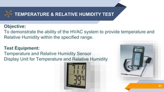
HEATING
VENTILATION &
AIRCONDITIONING
HELLO!I am Avishek Sensarma
I am here to give a presentations on HVAC.
You can find me at
avishek.sensarma8336055587@gmail.com
2
CONTENT
▰ Introduction of HVAC
▰ History of HVAC
▰ Application of HVAC
▰ Component of HVAC
▰ Clean Area /Room
▰ Classification of Clean Area
▰ Airlocks
▰ Qualification of HVAC system 3
INTRODUCTION
4
1
H= Heating
V= Ventilation
AC= Air Conditioning
5
INTRODUCTION OF HVAC
6
▰ HVAC refers to Systems which are mechanical arrangements
that treats outside air to produce cleaned (from dust and
microbes) conditioned air ( temperature and humidity) which is
circulated or re-circulated for use in controlled and critical areas
within the pharmaceutical manufacturing space
OR
▰ Can be simply said to be a utility system used to provide air
ventilation, heating, cooling and air conditioning services to a
building or a pharmaceutical space for drug manufacturing
HISTORY
7
2
The first comfort HVAC
system was installed in
New York Stock
Exchange in the Year
of 1902 8
FATHER OF HVAC SYETEM
.
9
Willis Haviland Carrier (November 26, 1876 –
October 7, 1950) was an American engineer,
best known for inventing modern air
conditioning . Carrier invented the first
electrical air conditioning unit in 1902 and, in
1915, he founded Carrier Corporation , a
company specializing in the manufacture and
distribution of heating, ventilation, and air
conditioning (HVAC) systems.
APPLICATION
10
3
SHOPPING MALL
100%
185,244 users
HOTELS
11
HOSPITALS
PHARMA INDUSTRIES
TELECOM INDUSTRIES
IT INDUSTRIES
COMPONENTS
12
4
COMPONENTS OF HVAC
13
The HVAC system is mainly consists of Air Handling Units (AHU).
HVAC is the central unit to which AHU is connected.
Components of AHUs are as follows :
 Weather louvre
 Silencer
 Flow rate controller
 Control damper
 Fan/Blower
COMPONENTS OF HVAC
14
Components of AHUs are as follows :
 Heating Unit
 Cooling Unit/ Dehumidifier
 Humidifier
 Filters
 Ducts
OVERVIEW COMPONENTS
15
FilterSilencer
Terminal filter
Weather louvre
Control damper
FanFlow rate controller
Humidifier
Heating
coil
Cooling coil
with droplet
separator
Production Room
+
Prefilter
INSIDE THE AIR HANDLING UNIT
16
17
SCHEMATIC DIAGRAM OF AHU
AHU CIRCULATION TYPE
100% FRESH AIR TYPE RECIRCULATION TYPE
18
WEATHER LOUVRE
To prevent insects,
leaves, dirt and rain from
entering
19
SILENCER
To reduce noise caused
by Air Circulation.
20
FAN /BLOWER
To suck the fresh air from
the atmosphere or from
the production room.
Fan blower is run by a
powerful motor.
21
FLOW RATE CONTROLLER
▰Automated adjustment
of volume of air (night and
day, pressure control)
22
CONTROL DUMPER
▰Fixed adjustment of volume of
air
23
HEATING UNIT
▰To heat the air to the
proper temperature
24
COOLING UNIT /DEHUMIDIFIER
▰To cool the air to the
required temperature or to
remove moisture from the
air
25
HUMIDIFIER
▰To bring the air to the
proper humidity, if too low
26
DUCTS
▰To transport the air
27
FILTERS
▰To eliminate particles of
pre-determined
dimensions and/or micro-
organisms
28
FILTERS TYPES
29
DUST FILTER
STANDARD
COARSE FINE
AEROSOL
ULPAHEPA
F5-F9G1-G4 H11-H13 U14-U17
GRADE WISE FILTER EFFICENCY
30
GRADE WISE FILTER EFFICENCY
31
CLEAN AREA/ROOM
32
5
33
NASA's Goddard
Space Flight Center
is Worlds Largest
Clean Room
WHAT IS CLEAN ROOM
l A room/area in which the concentration of airborne particles is
controlled.
l A room/area, which is constructed and used in a manner to
minimize the introduction, generation and retention of particles
inside the room.
l A room/area in which other relevant parameters e.g.
Temperature, Humidity and Pressure are controlled as
necessary.
34
WHY CLEAN ROOM
l To avoid cross contamination.
l To avoid physical contamination like Air borne Foreign particles
and fibers.
l To avoid microbial contamination.
35
CLEAN ROOM CLASSIFICATION AS PER ISO
36
CLEAN ROOM CLASSIFICATION AS PER EU
37
CLEAN ROOM CLASSIFICATION AS PER USFDA
38
AIRLOCKS
39
6
WHAT IS AIRLOCK
Airlock is a small room with controlled air flow acting as barrier
between spaces, minimises volume of contaminated air that is
introduced into the cleaner area when door is opened.
▰ Air lock should open and close fast( minimise time of
contamination
▰ No simultaneous opening of booth doors
▰ High air change rate and smaller airlock ensure faster recovery
time
40
TYPES OF AIRLOCK
Airlock are mainly four types
• Bubble type
• Cascade type
• Sink type
• Dual Compartment Airlock
41
42
HVAC QUALIFICATION
43
7
44
HVAC QUALIFICATION
QUALICATION FLOW CHART
QUALIFICATION ACTIVITY FLOW
46
Installation
Qualification
Design
Qualification
Operation
Qualification
Performance
Qualification
DESIGN QUALIFICATION
47
Design Qualification includes
•System description.
•Basic Design Concept
•Methodology
•Acceptance Criteria
•Summary & Conclusion
INSTALLATION QUALIFICATION
48
Installation Qualification includes
• Equipment specification & Identification
• Major component Verification
• Levelling and Alignment
• Verification of Installation & Verification of Utilities
• Check List for Duct Network
• Drawings & Documents
• SOP Verification
OPERATION QUALIFICATION
49
Operation Qualification includes
• Instrument Calibration
• Key Functionality
• Operational Checks
• Safety Features
• SOP verification
• PM planner verification.
PERFORMANCE QUALIFICATION
50
Performance Qualification includes (Cont..)
• Pressure Drop across the HEPA and Fine filters of Air Handling Unit
• Air Velocity Measurement and Calculation of Air Changes
• Integrity test of HEPA filters
• Differential Pressure Test
• Temperature and Relative Humidity Test
PERFORMANCE QUALIFICATION
51
Performance Qualification includes (cont..)
• Air Flow Direction Test
• Cleanliness Class Verification (Non viable Particle Count)
• Sound level Test
• Light Level Test
• Air Borne Viable Particle Monitoring
• Recovery test
REQUALIFICATION
52
Scheduled Qualification
Scheduled qualifications as per validation plan shall be carried out.
Unscheduled Qualification shall be carried out incase of ;
• Substitution of existing HVAC system with a new system.
• Replacement of existing HEPA-Filter or critical component.
• Any major modification to the existing HVAC system since purchase
or after the last performance qualification.
• Frequent surpassing of the alert or action limits of routine
environmental monitoring parameters
PERFORMANCE
QUALIFICATION
TESTS
53
PRESSURE DROP ACROSS THE HEPA AND
FINE FILTERS OF AIR HANDLING UNIT
54
Objective:
The purpose of this test is to check the Clogged or clean condition of the
across filters of the Air Handling Unit.
Test Equipment:
Differential pressure Transmitter or Manometer
Procedure for HEPA, Fine and Pre Filters:
Ensure that the differential pressure transmitter is connected to before the
filter and after the filter. Check the status of the filter whether the filter is in
clean condition or Clogged condition.
Acceptance Criteria:
HEPA, Pre and Fine filters should be in clean condition
AIR VELOCITY MEASUREMENT AND
CALCULATION OF AIR CHANGES
55
Objective:
To demonstrate that the air system is balanced and capable of delivering air
velocities and providing number of air changes per hour in the respective
rooms as per requirement.
Test Equipment:
Digital Anemometer / Vane Anemometer
Procedure:
For compliance of air change rate, velocity to be measured at 5 different
locations 2” below the each Terminal HEPA Filter or Grill (Four Corners and
center) with the help of calibrated Anemometer.
AIR VELOCITY MEASUREMENT AND
CALCULATION OF AIR CHANGES
56
Calculate the average velocity of the air coming from Supply Grill / Terminal
Filter.
Calculate the total airflow from all the Supply Grill / Terminal Filter in the room
and add values to get the total airflow in the room (CFM).
Acceptance Criteria:
Average velocity and subsequent airflow through supply terminals should
meet the design criteria of air change rate as per requirement
INTEGRITY (LEAK) TEST OF HEPA FILTER
57
Objective:
To check the installation integrity of the HEPA Filter in Air Handling Units.
Test Equipment:
• Aerosol generator
• Aerosol Photometer, duly calibrated with national /
international traceability.
• DOP Liquid (Di Octyl Phthalate) /
PAO (Poly Alpha Olefin) Liquid
INTEGRITY (LEAK) TEST OF HEPA FILTER
58
Procedure:
Position the Aerosol generator and introduce Aerosol into the upstream air,
ahead of the HEPA filters, at the concentration of 80-100 g per liter of air at
the filter’s designed airflow rating and set the instrument at 100%
concentration. Scan the downstream side of the filter with an appropriate
photometer probe at a sampling rate of at least 1 ft3 / min.
Acceptance Criteria:
During scanning percentage of the PAO/ DOP Liquid penetration shown by
photometer should be less than 0.01% through the filter media and should be
‘zero’ through mounting joints for 99.97 efficiency HEPA Filters and 0.001%
for 99.997 Efficiency.
DIFFERENTIAL PRESSURE TEST
59
Objective:
To demonstrate the capability of air system and to provide pressure gradient
among different rooms.
Equipment Used:
Differential Pressure Display Unit or BMS System/Magnehelic Gauges .
DIFFERENTIAL PRESSURE TEST
60
Procedure:
To avoid unexpected changes in air pressure and to establish a baseline, all
doors in the facility must be closed and no man movement to be allowed
during the observations. Observe the differential pressure through Display
Unit or BMS System / Magnehelic Gauges .
Acceptance Criteria:
Pressure differentials should meet the requirement as specified in system
specification.
TEMPERATURE & RELATIVE HUMIDITY TEST
61
Objective:
To demonstrate the ability of the HVAC system to provide temperature and
Relative Humidity within the specified range.
Test Equipment:
Temperature and Relative Humidity Sensor
Display Unit for Temperature and Relative Humidity
TEMPERATURE & RELATIVE HUMIDITY TEST
62
Procedure:
Observe the temperature and relative humidity through respective display
unit wherever installed. Use Hygrometer to check the reading of Temperature
and RH in other rooms.
Temperature and RH in the area to be checked and recorded in Static as well
as Dynamic Condition.
Acceptance Criteria:
Temperature and relative humidity should meet the requirement as specified
in system specification.
AIR FLOW DIRECTION TEST
63
Objective
To ensure that the HFC system in aseptic area, LAF and Pass box provide
unidirectional airflow up to the working height during rest and operating
condition.
To demonstrate that the air pressure is balanced and air is flowing from high-
pressure zone to low pressure zone.
Procedure
Place a torch of Dry Ice / TiCl4 under HFC.
Observe the flow of Dry Ice / TiCl4 smoke at the filter downstream.
Videotape the smoke flow pattern.
AIR FLOW DIRECTION TEST
64
Acceptance Criteria
Under HFC, Smoke Flow should be unidirectional up to working height
Smoke should flow from the higher-pressure zone to low-pressure zone
between the rooms when the door is open.
CLEANLINESS CLASS VERIFICATION (NON
VIABLE PARTICLE COUNT)
65
Objective:
To verify that the clean rooms are having cleanliness class as
specified in specification sheet.
Test Equipment:
Air borne particulate counter of 1 CFM suction capacity, duly
calibrated with traceability to national / international standard.
Procedure:
Particulate counting shall be carried out at predefined locations.
Particulate Count shall be taken in 3 rounds of Static condition
and 3 rounds of Dynamic condition.
CLEANLINESS CLASS VERIFICATION (NON
VIABLE PARTICLE COUNT)
66
Static Condition:
In static condition all the machines shall be kept switched ‘OFF’. Only
restricted man movement shall take place.
Dynamic Condition:
In dynamic condition the operator shall mock desired operation and
restricted man movement shall take place.
Acceptance Criteria:
Clean room or clean zone shall meet the acceptance criteria for an air
borne particulate as referred in standard ISO 14644-1.
AIR BORNE VIABLE PARTICLE MONITORING
67
Objective:
To determine the air borne microbial contamination level in critical
area.
Air borne microbial count by settling plate exposure method:
Pre incubated SCDA Media plates shall be exposed in Locations
mentioned for 4 hours and incubated for 48 hours at 30°C to 35°C
followed by next 72 hours at 20°C to 25°C.Record the results in
respective format. PDA plates shall be exposed weekly to monitor
the fungal counts. SCDA plates shall be incubated once in fifteen
days to monitor the anaerobic Microorganisms
AIR BORNE VIABLE PARTICLE MONITORING
68
Air borne microbial count by Active Air Sampling:
To check the Viable Air borne particle count active air
sampling is done and incubate the tested Cassettes for 48
hours at 30°C to 35°C and further for 72 hours at 20°C to
25°C and observations are recorded in the respective format.
Acceptance Criteria:
All the Parameters performed in the area should meet the
following requirements
SOUND LEVEL TEST
69
Objective:
To verify that the sound level is in limit in the clean room area.
Test Equipment:
Sound Level Meter, duly calibrated with traceability to national /
international standard.
Procedure:
Take the reading at 5 locations in the room and take the average of the
sound in the unit of decibels.
Acceptance Criteria:
The clean room or clean zone shall meet the acceptance criteria for sound
level as mentioned below.
LIGHT LEVEL TEST
70
Objective:
To verify that the Light level is in limit in clean room area.
Test Equipment:
Lux Meter, duly calibrated with traceability to national / international standard.
Procedure:
Take the reading at 5 locations in the room and take the average of the light
level in the unit of Lux.
Acceptance Criteria:
The clean room or clean zone shall meet the acceptance criteria for light level
as mentioned below.
RECOVERY TEST
71
Objective:
To establish the recovery time frame for the area to attain the required
conditions after the simulation of particle counts from class A & class B.
Test Equipment:
Non-viable particle counter dually calibrated.
Procedure:
Simulate and ensure to a count equivalent to that of grade C areas at rest by
the following methods as below:
 Personnel Movement.
 Garments dusting.
RECOVERY TEST
72
Operate the Air borne non – viable particulate counter in the Class A & B
areas and continuously operate the non viable particulate counter and
note down the time taken after restoration as equivalent to class A & B.
Acceptance Criteria:
During restoration the particle count limits should fall in the class limits (as
referred in standard ISO 14644-1).
73
Any questions?
You can find me at
@8336055587 &
avishek.sensarma8336055587@gmail.com

Presentation on HVAC

  • 1.
  • 2.
    HELLO!I am AvishekSensarma I am here to give a presentations on HVAC. You can find me at avishek.sensarma8336055587@gmail.com 2
  • 3.
    CONTENT ▰ Introduction ofHVAC ▰ History of HVAC ▰ Application of HVAC ▰ Component of HVAC ▰ Clean Area /Room ▰ Classification of Clean Area ▰ Airlocks ▰ Qualification of HVAC system 3
  • 4.
  • 5.
  • 6.
    INTRODUCTION OF HVAC 6 ▰HVAC refers to Systems which are mechanical arrangements that treats outside air to produce cleaned (from dust and microbes) conditioned air ( temperature and humidity) which is circulated or re-circulated for use in controlled and critical areas within the pharmaceutical manufacturing space OR ▰ Can be simply said to be a utility system used to provide air ventilation, heating, cooling and air conditioning services to a building or a pharmaceutical space for drug manufacturing
  • 7.
  • 8.
    The first comfortHVAC system was installed in New York Stock Exchange in the Year of 1902 8
  • 9.
    FATHER OF HVACSYETEM . 9 Willis Haviland Carrier (November 26, 1876 – October 7, 1950) was an American engineer, best known for inventing modern air conditioning . Carrier invented the first electrical air conditioning unit in 1902 and, in 1915, he founded Carrier Corporation , a company specializing in the manufacture and distribution of heating, ventilation, and air conditioning (HVAC) systems.
  • 10.
  • 11.
    SHOPPING MALL 100% 185,244 users HOTELS 11 HOSPITALS PHARMAINDUSTRIES TELECOM INDUSTRIES IT INDUSTRIES
  • 12.
  • 13.
    COMPONENTS OF HVAC 13 TheHVAC system is mainly consists of Air Handling Units (AHU). HVAC is the central unit to which AHU is connected. Components of AHUs are as follows :  Weather louvre  Silencer  Flow rate controller  Control damper  Fan/Blower
  • 14.
    COMPONENTS OF HVAC 14 Componentsof AHUs are as follows :  Heating Unit  Cooling Unit/ Dehumidifier  Humidifier  Filters  Ducts
  • 15.
    OVERVIEW COMPONENTS 15 FilterSilencer Terminal filter Weatherlouvre Control damper FanFlow rate controller Humidifier Heating coil Cooling coil with droplet separator Production Room + Prefilter
  • 16.
    INSIDE THE AIRHANDLING UNIT 16
  • 17.
  • 18.
    AHU CIRCULATION TYPE 100%FRESH AIR TYPE RECIRCULATION TYPE 18
  • 19.
    WEATHER LOUVRE To preventinsects, leaves, dirt and rain from entering 19
  • 20.
    SILENCER To reduce noisecaused by Air Circulation. 20
  • 21.
    FAN /BLOWER To suckthe fresh air from the atmosphere or from the production room. Fan blower is run by a powerful motor. 21
  • 22.
    FLOW RATE CONTROLLER ▰Automatedadjustment of volume of air (night and day, pressure control) 22
  • 23.
  • 24.
    HEATING UNIT ▰To heatthe air to the proper temperature 24
  • 25.
    COOLING UNIT /DEHUMIDIFIER ▰Tocool the air to the required temperature or to remove moisture from the air 25
  • 26.
    HUMIDIFIER ▰To bring theair to the proper humidity, if too low 26
  • 27.
  • 28.
    FILTERS ▰To eliminate particlesof pre-determined dimensions and/or micro- organisms 28
  • 29.
    FILTERS TYPES 29 DUST FILTER STANDARD COARSEFINE AEROSOL ULPAHEPA F5-F9G1-G4 H11-H13 U14-U17
  • 30.
    GRADE WISE FILTEREFFICENCY 30
  • 31.
    GRADE WISE FILTEREFFICENCY 31
  • 32.
  • 33.
    33 NASA's Goddard Space FlightCenter is Worlds Largest Clean Room
  • 34.
    WHAT IS CLEANROOM l A room/area in which the concentration of airborne particles is controlled. l A room/area, which is constructed and used in a manner to minimize the introduction, generation and retention of particles inside the room. l A room/area in which other relevant parameters e.g. Temperature, Humidity and Pressure are controlled as necessary. 34
  • 35.
    WHY CLEAN ROOM lTo avoid cross contamination. l To avoid physical contamination like Air borne Foreign particles and fibers. l To avoid microbial contamination. 35
  • 36.
  • 37.
  • 38.
  • 39.
  • 40.
    WHAT IS AIRLOCK Airlockis a small room with controlled air flow acting as barrier between spaces, minimises volume of contaminated air that is introduced into the cleaner area when door is opened. ▰ Air lock should open and close fast( minimise time of contamination ▰ No simultaneous opening of booth doors ▰ High air change rate and smaller airlock ensure faster recovery time 40
  • 41.
    TYPES OF AIRLOCK Airlockare mainly four types • Bubble type • Cascade type • Sink type • Dual Compartment Airlock 41
  • 42.
  • 43.
  • 44.
  • 45.
  • 46.
  • 47.
    DESIGN QUALIFICATION 47 Design Qualificationincludes •System description. •Basic Design Concept •Methodology •Acceptance Criteria •Summary & Conclusion
  • 48.
    INSTALLATION QUALIFICATION 48 Installation Qualificationincludes • Equipment specification & Identification • Major component Verification • Levelling and Alignment • Verification of Installation & Verification of Utilities • Check List for Duct Network • Drawings & Documents • SOP Verification
  • 49.
    OPERATION QUALIFICATION 49 Operation Qualificationincludes • Instrument Calibration • Key Functionality • Operational Checks • Safety Features • SOP verification • PM planner verification.
  • 50.
    PERFORMANCE QUALIFICATION 50 Performance Qualificationincludes (Cont..) • Pressure Drop across the HEPA and Fine filters of Air Handling Unit • Air Velocity Measurement and Calculation of Air Changes • Integrity test of HEPA filters • Differential Pressure Test • Temperature and Relative Humidity Test
  • 51.
    PERFORMANCE QUALIFICATION 51 Performance Qualificationincludes (cont..) • Air Flow Direction Test • Cleanliness Class Verification (Non viable Particle Count) • Sound level Test • Light Level Test • Air Borne Viable Particle Monitoring • Recovery test
  • 52.
    REQUALIFICATION 52 Scheduled Qualification Scheduled qualificationsas per validation plan shall be carried out. Unscheduled Qualification shall be carried out incase of ; • Substitution of existing HVAC system with a new system. • Replacement of existing HEPA-Filter or critical component. • Any major modification to the existing HVAC system since purchase or after the last performance qualification. • Frequent surpassing of the alert or action limits of routine environmental monitoring parameters
  • 53.
  • 54.
    PRESSURE DROP ACROSSTHE HEPA AND FINE FILTERS OF AIR HANDLING UNIT 54 Objective: The purpose of this test is to check the Clogged or clean condition of the across filters of the Air Handling Unit. Test Equipment: Differential pressure Transmitter or Manometer Procedure for HEPA, Fine and Pre Filters: Ensure that the differential pressure transmitter is connected to before the filter and after the filter. Check the status of the filter whether the filter is in clean condition or Clogged condition. Acceptance Criteria: HEPA, Pre and Fine filters should be in clean condition
  • 55.
    AIR VELOCITY MEASUREMENTAND CALCULATION OF AIR CHANGES 55 Objective: To demonstrate that the air system is balanced and capable of delivering air velocities and providing number of air changes per hour in the respective rooms as per requirement. Test Equipment: Digital Anemometer / Vane Anemometer Procedure: For compliance of air change rate, velocity to be measured at 5 different locations 2” below the each Terminal HEPA Filter or Grill (Four Corners and center) with the help of calibrated Anemometer.
  • 56.
    AIR VELOCITY MEASUREMENTAND CALCULATION OF AIR CHANGES 56 Calculate the average velocity of the air coming from Supply Grill / Terminal Filter. Calculate the total airflow from all the Supply Grill / Terminal Filter in the room and add values to get the total airflow in the room (CFM). Acceptance Criteria: Average velocity and subsequent airflow through supply terminals should meet the design criteria of air change rate as per requirement
  • 57.
    INTEGRITY (LEAK) TESTOF HEPA FILTER 57 Objective: To check the installation integrity of the HEPA Filter in Air Handling Units. Test Equipment: • Aerosol generator • Aerosol Photometer, duly calibrated with national / international traceability. • DOP Liquid (Di Octyl Phthalate) / PAO (Poly Alpha Olefin) Liquid
  • 58.
    INTEGRITY (LEAK) TESTOF HEPA FILTER 58 Procedure: Position the Aerosol generator and introduce Aerosol into the upstream air, ahead of the HEPA filters, at the concentration of 80-100 g per liter of air at the filter’s designed airflow rating and set the instrument at 100% concentration. Scan the downstream side of the filter with an appropriate photometer probe at a sampling rate of at least 1 ft3 / min. Acceptance Criteria: During scanning percentage of the PAO/ DOP Liquid penetration shown by photometer should be less than 0.01% through the filter media and should be ‘zero’ through mounting joints for 99.97 efficiency HEPA Filters and 0.001% for 99.997 Efficiency.
  • 59.
    DIFFERENTIAL PRESSURE TEST 59 Objective: Todemonstrate the capability of air system and to provide pressure gradient among different rooms. Equipment Used: Differential Pressure Display Unit or BMS System/Magnehelic Gauges .
  • 60.
    DIFFERENTIAL PRESSURE TEST 60 Procedure: Toavoid unexpected changes in air pressure and to establish a baseline, all doors in the facility must be closed and no man movement to be allowed during the observations. Observe the differential pressure through Display Unit or BMS System / Magnehelic Gauges . Acceptance Criteria: Pressure differentials should meet the requirement as specified in system specification.
  • 61.
    TEMPERATURE & RELATIVEHUMIDITY TEST 61 Objective: To demonstrate the ability of the HVAC system to provide temperature and Relative Humidity within the specified range. Test Equipment: Temperature and Relative Humidity Sensor Display Unit for Temperature and Relative Humidity
  • 62.
    TEMPERATURE & RELATIVEHUMIDITY TEST 62 Procedure: Observe the temperature and relative humidity through respective display unit wherever installed. Use Hygrometer to check the reading of Temperature and RH in other rooms. Temperature and RH in the area to be checked and recorded in Static as well as Dynamic Condition. Acceptance Criteria: Temperature and relative humidity should meet the requirement as specified in system specification.
  • 63.
    AIR FLOW DIRECTIONTEST 63 Objective To ensure that the HFC system in aseptic area, LAF and Pass box provide unidirectional airflow up to the working height during rest and operating condition. To demonstrate that the air pressure is balanced and air is flowing from high- pressure zone to low pressure zone. Procedure Place a torch of Dry Ice / TiCl4 under HFC. Observe the flow of Dry Ice / TiCl4 smoke at the filter downstream. Videotape the smoke flow pattern.
  • 64.
    AIR FLOW DIRECTIONTEST 64 Acceptance Criteria Under HFC, Smoke Flow should be unidirectional up to working height Smoke should flow from the higher-pressure zone to low-pressure zone between the rooms when the door is open.
  • 65.
    CLEANLINESS CLASS VERIFICATION(NON VIABLE PARTICLE COUNT) 65 Objective: To verify that the clean rooms are having cleanliness class as specified in specification sheet. Test Equipment: Air borne particulate counter of 1 CFM suction capacity, duly calibrated with traceability to national / international standard. Procedure: Particulate counting shall be carried out at predefined locations. Particulate Count shall be taken in 3 rounds of Static condition and 3 rounds of Dynamic condition.
  • 66.
    CLEANLINESS CLASS VERIFICATION(NON VIABLE PARTICLE COUNT) 66 Static Condition: In static condition all the machines shall be kept switched ‘OFF’. Only restricted man movement shall take place. Dynamic Condition: In dynamic condition the operator shall mock desired operation and restricted man movement shall take place. Acceptance Criteria: Clean room or clean zone shall meet the acceptance criteria for an air borne particulate as referred in standard ISO 14644-1.
  • 67.
    AIR BORNE VIABLEPARTICLE MONITORING 67 Objective: To determine the air borne microbial contamination level in critical area. Air borne microbial count by settling plate exposure method: Pre incubated SCDA Media plates shall be exposed in Locations mentioned for 4 hours and incubated for 48 hours at 30°C to 35°C followed by next 72 hours at 20°C to 25°C.Record the results in respective format. PDA plates shall be exposed weekly to monitor the fungal counts. SCDA plates shall be incubated once in fifteen days to monitor the anaerobic Microorganisms
  • 68.
    AIR BORNE VIABLEPARTICLE MONITORING 68 Air borne microbial count by Active Air Sampling: To check the Viable Air borne particle count active air sampling is done and incubate the tested Cassettes for 48 hours at 30°C to 35°C and further for 72 hours at 20°C to 25°C and observations are recorded in the respective format. Acceptance Criteria: All the Parameters performed in the area should meet the following requirements
  • 69.
    SOUND LEVEL TEST 69 Objective: Toverify that the sound level is in limit in the clean room area. Test Equipment: Sound Level Meter, duly calibrated with traceability to national / international standard. Procedure: Take the reading at 5 locations in the room and take the average of the sound in the unit of decibels. Acceptance Criteria: The clean room or clean zone shall meet the acceptance criteria for sound level as mentioned below.
  • 70.
    LIGHT LEVEL TEST 70 Objective: Toverify that the Light level is in limit in clean room area. Test Equipment: Lux Meter, duly calibrated with traceability to national / international standard. Procedure: Take the reading at 5 locations in the room and take the average of the light level in the unit of Lux. Acceptance Criteria: The clean room or clean zone shall meet the acceptance criteria for light level as mentioned below.
  • 71.
    RECOVERY TEST 71 Objective: To establishthe recovery time frame for the area to attain the required conditions after the simulation of particle counts from class A & class B. Test Equipment: Non-viable particle counter dually calibrated. Procedure: Simulate and ensure to a count equivalent to that of grade C areas at rest by the following methods as below:  Personnel Movement.  Garments dusting.
  • 72.
    RECOVERY TEST 72 Operate theAir borne non – viable particulate counter in the Class A & B areas and continuously operate the non viable particulate counter and note down the time taken after restoration as equivalent to class A & B. Acceptance Criteria: During restoration the particle count limits should fall in the class limits (as referred in standard ISO 14644-1).
  • 73.
    73 Any questions? You canfind me at @8336055587 & avishek.sensarma8336055587@gmail.com