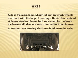
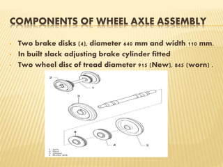
ABES ENGINEERING COLLEGE GHAZIABAD
INDUSTRIAL SUMMER TRAINING PRESENTATTION
SESSION 2015-16
COMPLETED AT ELECTRIC LOCO SHED GHAZIABAD
SUBMITTED TO: SUBMITTED BY:
MR. MAYANK KUSHWAHA PALASH AWASTHI
(ASTT. PROFESSOR) 1203240100
PRESENTATION AT A GLANCE
• HISTORY
• MAINTENANCE DEPARTMENTS AT LOCOSHED
• MAINTENANCE OF DIFFERENT TYPES OF LOCOS
• PANTOGRAPH
• WHEEL AND AXLE ASSEMBLY
• AIR BRAKE SYSTEM
• ADVANTAGES OF ELECTRIC LOCOMOTIVES
WHAT IS LOCO AND LOCO SHED?
• Loco is the engine of the loco motives .
• It consists of two bogies i.e. 12 wheels .
• The driver also drives the train in the loco.
• The place at which the maintenance of locos is
done, known as loco shed depending upon type
of locos they are termed as electric loco or
diesel loco sheds.
HISTORY
• 1st Electric locomotive was built by a Scotsman, Robert
Davidson of Aberdeen in 1837 & powered by batteries.
• 1st Electric passenger train was presented by Werner
von Siemens at Berlin in 1879. Driven by a 2.2 kW motor
& reached a maximum speed of 13 km/h
CONTINUED……
• Locomotives in India consist of electric and diesel
locomotives. Locomotives are also
called locos or engines.
• An electric locomotive is a locomotive powered by
electricity from overhead lines, an on-board energy
storage device such as a chemical battery or fuel cell
• Electricity is used to eliminate smoke and take
advantage of the high efficiency of electric motors.
• Electric Loco Shed was set in 1976 by Railway
Electrification Organisation (8910 SQ. MTRS).
INITIAL COST
Rs. 1.5 (IN CRORES)
PRESENT LOCO HOLDING
185
MAINTENANCE DEPARTMENTS
• M-1 :WHEEL MAINTENANCE
• M-2: BODY REPAIRING
• M-3:PENTOGRAPH
• M-5:BRAKES
• M-5’: COMPRESSORS
LOCOS MAINTENANCE AT SHED
• Ghaziabad electric loco shed serves the Delhi area. It
houses and maintains India's fastest locomotives which
are mostly used in Rajdhani, Shatabdi and Duronto
Expresses. It holds 47 WAP-1 locos as of 2008. It also has
WAP-4, WAP-5, WAP-7 and WAG-5 locos.
• "W" means broad gauge. "A" mean AC electric traction
motive power. "P" means suitable for Passenger service.
"5" denotes that this locomotive is chronologically the
fifth electric locomotive model used by the railways for
passenger service
PANTOGRAPH
• Now a days many locos are running through Electricity
with the help of OHE line.
• A pantograph is a device that collects electric current
from overhead lines for electric trains or trams.
• Pantograph is used to connect the loco with OHE line
• Pantograph draws 25 KV of electricity from OHE line,
which is very high AC voltage.
CONTINUED….
• It is spring loaded and pushes a contact shoe up against
the contact wire to draw the electricity needed to run
the train.
• Pantographs are typically operated by compressed air
from the vehicle's braking system, either to raise the unit
and hold it against the conductor .
HOW DOES A PANTOGRAPH PERFORMS
WHEEL AND AXLE ASSEMBLY
• This is the part which is just adjacent to the tracks. It
basically consists of four main parts
a) Wheel
b) Axle
c) Bearing and Housing
• WHEEL
Wheel is specifically made cylindrical portion having
an outer edge shape to fit in the railway track. The
material is stainless steel.
CONTINUED……
AXLE
• Axle is the main long cylindrical bar on which wheels
are fixed with the help of bearings. This is also made of
stainless steel as above. Each axle contains 2 wheels,
the brake cylinders are also attached to it and in case
of coaches, the braking discs are fixed on to the axle.
COMPONENTS OF WHEEL AXLE ASSEMBLY
• Two brake disks (4), diameter 640 mm and width 110 mm.
• In built slack adjusting brake cylinder fitted
• Two wheel disc of tread diameter 915 (New), 845 (worn) .
AXLE BEARINGS
• A taper roller cartridge type bearing is used and it
makes up a preassembled unit. The axle bearings on the
bogie are fitted with sensors for detecting speed (whose
signal is elaborated by the ant slipping system) and a
current return device.
• The ends of the control arms are fitted with centering
devices for the primary suspension spring assembly. The
bearing lubricating plug is fitted in the lower part.
CONTINUED……
1. Double cup
2. Sealing system
3. Backing ring
AXLE BEARING LONGITUDINAL SECTION
AIR BRAKE SYSTEM
In Air Brake system compressed air is used for
operating the brake system. The locomotive
compressor charges the feed pipe and the brake
pipes throughout the length of the train. The
feed pipe is connected to the auxiliary
reservoirs and the brake pipe is connected to
the brake cylinders through the distributor
valve.
COMPONENTS OF AIR BRAKE SYSTEM
• Brake Container (Brake Equipment Panel)
• or Pressure Tanks (125 litres, 75 litres, 6 litres)
• Indicators
• Distributor valve
• B.P./F.P. Couplings and Hoses
• Emergency Brake Pull Box
• Emergency Brake valve
• Bogie Brake Equipment, consisting of-
• Brake Discs
• Speed Sensor/Pulse Generator
TYPES OF AIR BRAKE SYSTEM
Straight air brake: In the air brake's simplest form, called
the straight air system, compressed air pushes on a piston in
a cylinder. The piston is connected through mechanical
linkage to brake shoes that can rub on the train wheels, using
the resulting friction to slow the train. The mechanical linkage
can become quite elaborate, as it evenly distributes force
from one pressurized air cylinder to 8 or 12 wheels.
The pressurized air comes from an air compressor in the
locomotive and is sent from car to car by a train line made up
of pipes beneath each car and hoses between cars. The
principal problem with the straight air braking system is that
any separation between hoses and pipes causes loss of air
pressure and hence the loss of the force applying the brakes.
This could easily cause a runaway train. Straight air brakes
are still used on locomotives, although as a dual circuit
system, usually with each bogie (truck) having its own circuit.
WESTINGHOUSE AIR BRAKE
CONTINUED…
• In order to design a system without the shortcomings of
the straight air system, Westinghouse invented a system
wherein each piece of railroad rolling stock was
equipped with an air reservoir and a triple valve, also
known as a control valve
• The triple valve is described as being so named as it
performs three functions: Charging air into an air tank
ready to be used, applying the brakes, and releasing
them
BRAKE APPLICATION
• The driver lowers the Break Pipe pressure by engaging
the A-9 valve in the engine.
• This loss in pressure is transmitted from one bogey to
the next.
• Since cylinder pressure remains same, the main
diaphragm(above the cylinder) moves up in response to
the pressure drop in Distributor Valve.
• As a result the ‘three pressure valve’ opens the AR
Brake Cylinder port .
• Thus the AR pressure of 6 kg/cm^2 flows into the Brake
Cylinder through pressure limiters which reduces BC
pressure to 3.8.
BRAKE RELEASE
• BP pressure is again increased to 5 kg/cm2.
• Consequently, main diaphragm move down and
the ‘three pressure valve’ closes the AR-BC port
and opens the BC- atm port.
• BC pressure is released and the brake caliper is
disengaged.
ADVANTAGES OF ELECTRIC LOCOMOTIVES
• Electric engines do not produce much heat and noise.
• Electric engines are therefore easier to maintain
whereas the moving parts of a diesel engine require
constant maintenance.
• The simple nature of the electric engine makes them
efficient and powerful.
• Electric engines are light weight, constituting only
motors and wheel axles, and have almost no moving
parts.
• Do Not Produce Smock.
Abes engineering college  ghaziabad

Abes engineering college ghaziabad

  • 1.
    ABES ENGINEERING COLLEGEGHAZIABAD INDUSTRIAL SUMMER TRAINING PRESENTATTION SESSION 2015-16 COMPLETED AT ELECTRIC LOCO SHED GHAZIABAD SUBMITTED TO: SUBMITTED BY: MR. MAYANK KUSHWAHA PALASH AWASTHI (ASTT. PROFESSOR) 1203240100
  • 2.
    PRESENTATION AT AGLANCE • HISTORY • MAINTENANCE DEPARTMENTS AT LOCOSHED • MAINTENANCE OF DIFFERENT TYPES OF LOCOS • PANTOGRAPH • WHEEL AND AXLE ASSEMBLY • AIR BRAKE SYSTEM • ADVANTAGES OF ELECTRIC LOCOMOTIVES
  • 3.
    WHAT IS LOCOAND LOCO SHED? • Loco is the engine of the loco motives . • It consists of two bogies i.e. 12 wheels . • The driver also drives the train in the loco. • The place at which the maintenance of locos is done, known as loco shed depending upon type of locos they are termed as electric loco or diesel loco sheds.
  • 4.
    HISTORY • 1st Electriclocomotive was built by a Scotsman, Robert Davidson of Aberdeen in 1837 & powered by batteries. • 1st Electric passenger train was presented by Werner von Siemens at Berlin in 1879. Driven by a 2.2 kW motor & reached a maximum speed of 13 km/h
  • 5.
    CONTINUED…… • Locomotives inIndia consist of electric and diesel locomotives. Locomotives are also called locos or engines. • An electric locomotive is a locomotive powered by electricity from overhead lines, an on-board energy storage device such as a chemical battery or fuel cell • Electricity is used to eliminate smoke and take advantage of the high efficiency of electric motors. • Electric Loco Shed was set in 1976 by Railway Electrification Organisation (8910 SQ. MTRS). INITIAL COST Rs. 1.5 (IN CRORES) PRESENT LOCO HOLDING 185
  • 6.
    MAINTENANCE DEPARTMENTS • M-1:WHEEL MAINTENANCE • M-2: BODY REPAIRING • M-3:PENTOGRAPH • M-5:BRAKES • M-5’: COMPRESSORS
  • 7.
    LOCOS MAINTENANCE ATSHED • Ghaziabad electric loco shed serves the Delhi area. It houses and maintains India's fastest locomotives which are mostly used in Rajdhani, Shatabdi and Duronto Expresses. It holds 47 WAP-1 locos as of 2008. It also has WAP-4, WAP-5, WAP-7 and WAG-5 locos. • "W" means broad gauge. "A" mean AC electric traction motive power. "P" means suitable for Passenger service. "5" denotes that this locomotive is chronologically the fifth electric locomotive model used by the railways for passenger service
  • 8.
    PANTOGRAPH • Now adays many locos are running through Electricity with the help of OHE line. • A pantograph is a device that collects electric current from overhead lines for electric trains or trams. • Pantograph is used to connect the loco with OHE line • Pantograph draws 25 KV of electricity from OHE line, which is very high AC voltage.
  • 9.
    CONTINUED…. • It isspring loaded and pushes a contact shoe up against the contact wire to draw the electricity needed to run the train. • Pantographs are typically operated by compressed air from the vehicle's braking system, either to raise the unit and hold it against the conductor .
  • 11.
    HOW DOES APANTOGRAPH PERFORMS
  • 12.
    WHEEL AND AXLEASSEMBLY • This is the part which is just adjacent to the tracks. It basically consists of four main parts a) Wheel b) Axle c) Bearing and Housing • WHEEL Wheel is specifically made cylindrical portion having an outer edge shape to fit in the railway track. The material is stainless steel.
  • 13.
  • 14.
    AXLE • Axle isthe main long cylindrical bar on which wheels are fixed with the help of bearings. This is also made of stainless steel as above. Each axle contains 2 wheels, the brake cylinders are also attached to it and in case of coaches, the braking discs are fixed on to the axle.
  • 15.
    COMPONENTS OF WHEELAXLE ASSEMBLY • Two brake disks (4), diameter 640 mm and width 110 mm. • In built slack adjusting brake cylinder fitted • Two wheel disc of tread diameter 915 (New), 845 (worn) .
  • 16.
    AXLE BEARINGS • Ataper roller cartridge type bearing is used and it makes up a preassembled unit. The axle bearings on the bogie are fitted with sensors for detecting speed (whose signal is elaborated by the ant slipping system) and a current return device. • The ends of the control arms are fitted with centering devices for the primary suspension spring assembly. The bearing lubricating plug is fitted in the lower part.
  • 17.
    CONTINUED…… 1. Double cup 2.Sealing system 3. Backing ring AXLE BEARING LONGITUDINAL SECTION
  • 18.
    AIR BRAKE SYSTEM InAir Brake system compressed air is used for operating the brake system. The locomotive compressor charges the feed pipe and the brake pipes throughout the length of the train. The feed pipe is connected to the auxiliary reservoirs and the brake pipe is connected to the brake cylinders through the distributor valve.
  • 19.
    COMPONENTS OF AIRBRAKE SYSTEM • Brake Container (Brake Equipment Panel) • or Pressure Tanks (125 litres, 75 litres, 6 litres) • Indicators • Distributor valve • B.P./F.P. Couplings and Hoses • Emergency Brake Pull Box • Emergency Brake valve • Bogie Brake Equipment, consisting of- • Brake Discs • Speed Sensor/Pulse Generator
  • 20.
    TYPES OF AIRBRAKE SYSTEM Straight air brake: In the air brake's simplest form, called the straight air system, compressed air pushes on a piston in a cylinder. The piston is connected through mechanical linkage to brake shoes that can rub on the train wheels, using the resulting friction to slow the train. The mechanical linkage can become quite elaborate, as it evenly distributes force from one pressurized air cylinder to 8 or 12 wheels. The pressurized air comes from an air compressor in the locomotive and is sent from car to car by a train line made up of pipes beneath each car and hoses between cars. The principal problem with the straight air braking system is that any separation between hoses and pipes causes loss of air pressure and hence the loss of the force applying the brakes. This could easily cause a runaway train. Straight air brakes are still used on locomotives, although as a dual circuit system, usually with each bogie (truck) having its own circuit.
  • 22.
  • 23.
    CONTINUED… • In orderto design a system without the shortcomings of the straight air system, Westinghouse invented a system wherein each piece of railroad rolling stock was equipped with an air reservoir and a triple valve, also known as a control valve • The triple valve is described as being so named as it performs three functions: Charging air into an air tank ready to be used, applying the brakes, and releasing them
  • 24.
    BRAKE APPLICATION • Thedriver lowers the Break Pipe pressure by engaging the A-9 valve in the engine. • This loss in pressure is transmitted from one bogey to the next. • Since cylinder pressure remains same, the main diaphragm(above the cylinder) moves up in response to the pressure drop in Distributor Valve. • As a result the ‘three pressure valve’ opens the AR Brake Cylinder port . • Thus the AR pressure of 6 kg/cm^2 flows into the Brake Cylinder through pressure limiters which reduces BC pressure to 3.8.
  • 25.
    BRAKE RELEASE • BPpressure is again increased to 5 kg/cm2. • Consequently, main diaphragm move down and the ‘three pressure valve’ closes the AR-BC port and opens the BC- atm port. • BC pressure is released and the brake caliper is disengaged.
  • 26.
    ADVANTAGES OF ELECTRICLOCOMOTIVES • Electric engines do not produce much heat and noise. • Electric engines are therefore easier to maintain whereas the moving parts of a diesel engine require constant maintenance. • The simple nature of the electric engine makes them efficient and powerful. • Electric engines are light weight, constituting only motors and wheel axles, and have almost no moving parts. • Do Not Produce Smock.