1) The document describes how to build a motorized zoetrope using an Arduino, motor, H-bridge, and potentiometer to control speed and direction. A zoetrope uses a series of still images to create the illusion of motion.
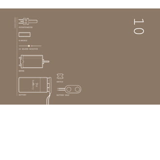
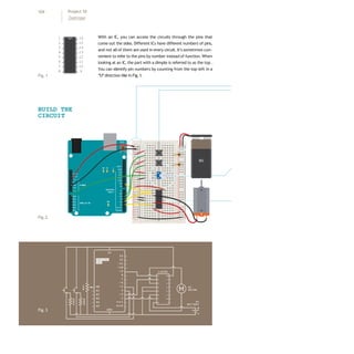
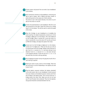
2) An H-bridge circuit is used to reverse the polarity of the motor and change its direction of rotation. The potentiometer controls motor speed, and switches control direction and on/off functions.
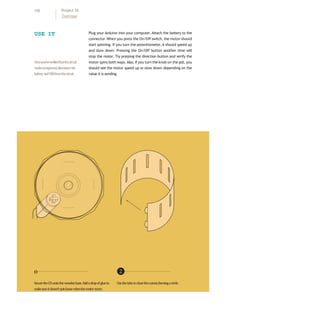
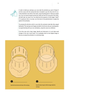
3) When assembled and the CD zoetrope is spun, looking through the slits creates the illusion of animated motion from the still images as in the first moving images before film.