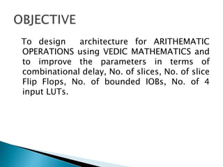
1) The document presents the design of arithmetic operations using Vedic mathematics to improve parameters like combinational delay, number of slices, flip flops, and LUTs compared to conventional methods.
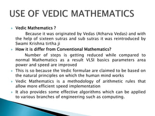
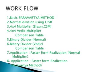
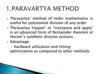
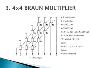
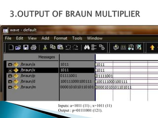
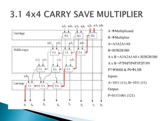
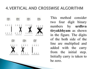
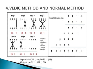
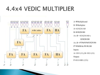
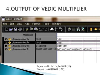
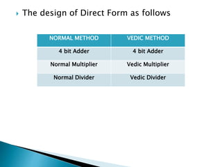
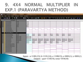
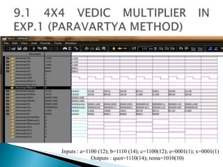
2) It describes the Vedic mathematics techniques of Paravartya and Urdhva Tiryagbhyam and shows their implementation in 4x4 multipliers and dividers in VHDL with improvements in delay and resource usage.
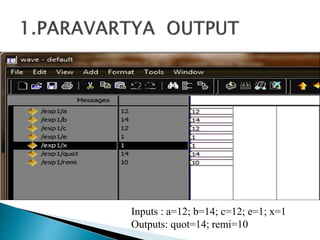
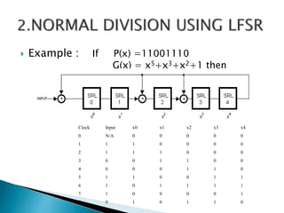
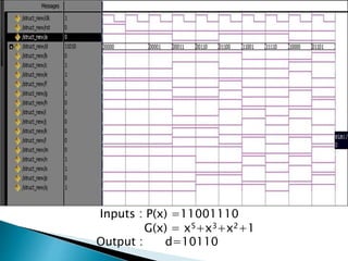
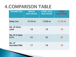
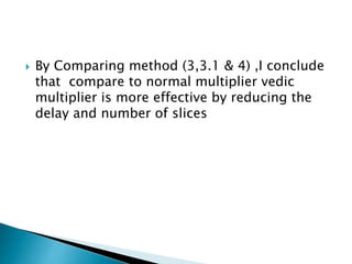
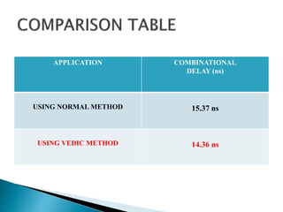
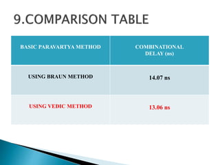
3) The experiments show that the Vedic multiplier and divider have lower delay and use fewer resources than conventional designs, with the Paravartya method also improving speed in applications like polynomial division.