Downloaded 309 times
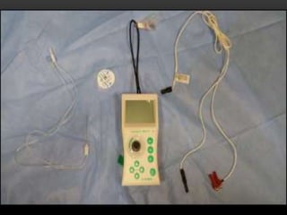
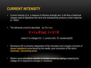


Dr. Yamini V S presented on the basics of peripheral nerve stimulation. Key points include: 1. Electrical nerve stimulation uses controlled electrical currents to locate nerves through eliciting motor responses or paraesthesia. 2. Modern nerve stimulators use constant current outputs to maintain stimulation strength despite tissue impedance changes. 3. Advances in stimulating needles, catheters, equipment, and techniques like transcutaneous nerve mapping have improved accuracy and reduced risk of nerve injury during peripheral nerve blocks. 4. Proper understanding of nerve physiology and anatomy remains essential for safe and effective use of peripheral nerve stimulation.


![CASE_PRESENTATION_ON_subdural_hematoma(SDH)[1 FINAL PPT]-1.pptx](https://cdn.slidesharecdn.com/ss_thumbnails/casepresentationonsubduralhematomasdh1finalppt-1-260129172522-d405d375-thumbnail.jpg?width=640&height=640&fit=bounds)


