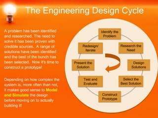
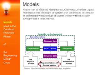
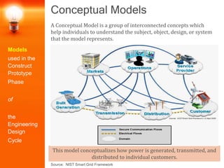
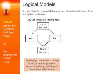
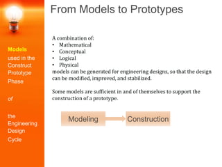
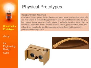
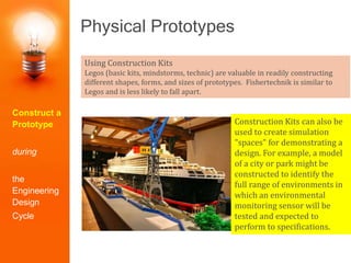
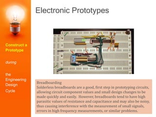
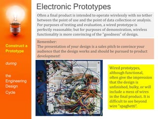
The Engineering
Design Cycle
Part 5:
Construct a Prototype
http://labs.ee.washington.edu/community/BasicEngDes/BasicEngDes_ConstructPrototype/
A problem has been identified
and researched. The need to
solve it has been proven with
credible sources. A range of
solutions have been identified
and the best of the bunch has
been selected. Now it's time to
construct a prototype!
Depending on how complex the
system is, more often than not,
it makes good sense to Model
and Simulate the design
before moving on to actually
building it!
The Engineering Design Cycle
Identify the
Problem
Construct
Prototype
Research the
Need
Select the
Best Solution
Design
Solutions
Redesign/
Iterate
Test and
Evaluate
Present the
Solution
Models
Models
used in the
Construct
Prototype
Phase
of
the
Engineering
Design
Cycle
Models can be Physical, Mathematical, Conceptual, or other Logical
Representations of designs or systems that can be used to simulate
or understand what a design or system will do without actually
having to test it in its entirety.
Source: https://en.wikipedia.org/wiki/Modeling_and_simulation
Models
Why?
• Reduce costs of prototyping, testing, and evaluating by more fully
understanding the system before actually having to build it.
• Increase the quality of products or designs.
• Document lessons learned for the benefit of future designs.
• Support more accurate hypotheses.
Source: https://en.wikipedia.org/wiki/Modeling_and_simulation
Models
used in the
Construct
Prototype
Phase
of
the
Engineering
Design
Cycle
Mathematical Models
The Ideal Operational Amplifier Model
Allows us to generate mathematical models of circuits containing
operational amplifiers. The mathematical model allows us to refine
circuits for simulation or prototype construction and to improve
chances for success when actually constructing a prototype.
v+ = v-
i+ = i- = 0
Vout = -2 Vin
Models
used in the
Construct
Prototype
Phase
of
the
Engineering
Design
Cycle
Mathematical Models
The Ideal Operational Amplifier Model
The mathematical model allows us to understand the circuit we are
building using paper calculations, so that the design can be adjusted
and time and effort saved in both circuit simulation and circuit
construction, testing, and evaluation.
v+ = v-
i+ = i- = 0
Models
used in the
Construct
Prototype
Phase
of
the
Engineering
Design
Cycle
Mathematical Models
Once mathematical models are used to refine circuit designs on
paper, they can be transferred to simulation to further verify the
design - thereby reducing the chances of failure during circuit
construction, test, and evaluation.
Simulation of circuits confirms overall circuit behavior using higher
order models of circuit components to ensure that overall
functionality is likely to be as designed and expected:
• Analog Circuits: SPICE, Oregano
• Digital Circuits: Logisim, gLogic, KTechLab
• Circuits Cloud, EasyEDA, GNU
Models
used in the
Construct
Prototype
Phase
of
the
Engineering
Design
Cycle
Physical Models
A Physical Model is a typically a (smaller or larger) copy of an
object or system that looks just like the system.
Models
used in the
Construct
Prototype
Phase
of
the
Engineering
Design
Cycle
Physical Models
However, sometimes it is a physical facsimile of a system that allows
some functionality of that system to be demonstrated (e.g. electrical
or sensor function).
The model on the right is a
physical model of a sequence
of street lamps designed to
test a Smart Lighting system.
The physical model allows
more comprehensive
simulation of the design.
Models
used in the
Construct
Prototype
Phase
of
the
Engineering
Design
Cycle
Conceptual Models
A Conceptual Model is a group of interconnected concepts which
help individuals to understand the subject, object, design, or system
that the model represents.
This model conceptualizes how power is generated, transmitted, and
distributed to individual customers.
Source: NIST Smart Grid Framework
Models
used in the
Construct
Prototype
Phase
of
the
Engineering
Design
Cycle
Logical Models
A Logic Flowchart is model that captures all possible decision flows
in a system or design.
Any design that makes a binary
or discontinuous (discrete)
series of decisions will benefit
from a Logical Flowchart.
Models
used in the
Construct
Prototype
Phase
of
the
Engineering
Design
Cycle
From Models to Prototypes
A combination of:
• Mathematical
• Conceptual
• Logical
• Physical
models can be generated for engineering designs, so that the design
can be modified, improved, and stabilized.
Some models are sufficient in and of themselves to support the
construction of a prototype.
Modeling Construction
Models
used in the
Construct
Prototype
Phase
of
the
Engineering
Design
Cycle
From Models to Prototypes
Other models, particularly for complex systems or systems that are
expensive or time consuming to build, provide the foundation for
moving to an intermediate step between modeling and prototype
construction – simulation.
Modeling ConstructionSimulation
Simulation Software:
• SPICE: general purpose, open source analog circuit simulator
• Matlab: general purpose programming, simulation, and modeling tool
• Automation Studio: fluid power, electrical, and control systems design
simulation
• Chemical Workbench: chemical kinetics simulation software
• Robologix: robotics simulation software
• LogiSim: digital logic circuits
• Atlas: electrical, optical, and thermal simulation of semiconductor devices
• and many more....
Models
used in the
Construct
Prototype
Phase
of
the
Engineering
Design
Cycle
Modeling and Simulation
Models, Models, Models
• Enable us to
mathematically,
conceptually, physically,
or logically express the
behavior of components in
a system or design.
• Once made and tested,
lead to more efficient
construction of a
prototype
Identify the
Problem
Construct
Prototype
Research the
Need
Select the
Best Solution
Design
Solutions
Redesign/
Iterate
Test and
Evaluate
Present the
Solution
Physical Prototypes
Often a working prototype is more convincing if it looks like the final
product (even though the materials to create this "look" may be
entirely different from materials used in the final design).
Construct a
Prototype
during
the
Engineering
Design
Cycle
Physical Prototypes
Using Everyday Materials
Cardboard, paper, poster board, foam-core, balsa wood, and similar materials
are very useful in constructing prototypes that emulate the form of a design,
but require simple tools (e.g. knife, scissors) and adhesives (e.g. tape, blue) to
construct. Everyday "found" objects such as straws, plastic bottles, cans, and
other items can also be used to supplement these basic but inexpensive
prototypes of design form.
Construct a
Prototype
during
the
Engineering
Design
Cycle
Construct a
Prototype
during
the
Engineering
Design
Cycle
Using Construction Kits
Legos (basic kits, mindstorms, technic) are valuable in readily constructing
different shapes, forms, and sizes of prototypes. Fishertechnik is similar to
Legos and is less likely to fall apart.
Physical Prototypes
Construction Kits can also be
used to create simulation
"spaces" for demonstrating a
design. For example, a model
of a city or park might be
constructed to identify the
full range of environments in
which an environmental
monitoring sensor will be
tested and expected to
perform to specifications.
Using 3D Printing (Additive Manufacturing)
3D printing, a computer that allows successive layers of various materials to
be deposited into a 3-D space using a type of industrial robot machine.
Almost any shape and geometry can be constructed using 3D printing,
making it an excellent choice for constructing prototypes (after the design is
selected) or models (before the design is selected).
Physical Prototypes
Construct a
Prototype
during
the
Engineering
Design
Cycle
Electronic Prototypes
Breadboarding
Solderless breadboards are a good, first step in prototyping circuits,
allowing circuit component values and small design changes to be
made quickly and easily. However, breadboards tend to have high
parasitic values of resistance and capacitance and may also be noisy,
thus causing interference with the measurement of small signals,
errors in high frequency measurements, or similar problems.
Construct a
Prototype
during
the
Engineering
Design
Cycle
Electronic Prototypes
Advanced Prototyping
To create a more convincing prototype or to eliminate noise and
parasitic problems with breadboards, use prototyping boards or
professionally printed and assembled PCBs (printed circuit boards) .
Construct a
Prototype
during
the
Engineering
Design
Cycle
Electronic Prototypes
Remember:
The presentation of your design is a sales pitch to convince your
audience that the design works and should be pursued to product
development!
Often a final product is intended to operate wirelessly with no tether
between the point of use and the point of data collection or analysis.
For purposes of testing and evaluation, a wired prototype is
perfectly reasonable; but for purposes of demonstration, wireless
functionality is more convincing of the "goodness" of design.
Wired prototypes,
although functional,
often give the impression
that the design is
unfinished, bulky, or will
include a mess of wires
in the final product. It is
difficult to see beyond
wire "spaghetti“.
Construct a
Prototype
during
the
Engineering
Design
Cycle
Construct a Prototype
Physical Prototypes
1. Can be constructed using:
– Everyday Materials
– Construction Kits
– 3-D Printing
– A combination of the
above
2. Focus on conveying
– Form and Shape of the
design
– Meaning and context of
the design
3. May or may not be functional
models
Identify the
Problem
Construct
Prototype
Research the
Need
Select the
Best Solution
Design
Solutions
Redesign/
Iterate
Test and
Evaluate
Present the
Solution
Thanks for joining us as we explored the fifth step of the
Engineering Design Cycle: Construct a Prototype.
Complete Educational Materials (including assignments,
quizzes, and recorded lectures) on the topic of Basic
Engineering Design can be found at:
http://labs.ee.washington.edu/community/BasicEngDes/
The Engineering Design Cycle

Basic Engineering Design (Part 5): Constructing a Prototype

  • 1.
    The Engineering Design Cycle Part5: Construct a Prototype http://labs.ee.washington.edu/community/BasicEngDes/BasicEngDes_ConstructPrototype/
  • 2.
    A problem hasbeen identified and researched. The need to solve it has been proven with credible sources. A range of solutions have been identified and the best of the bunch has been selected. Now it's time to construct a prototype! Depending on how complex the system is, more often than not, it makes good sense to Model and Simulate the design before moving on to actually building it! The Engineering Design Cycle Identify the Problem Construct Prototype Research the Need Select the Best Solution Design Solutions Redesign/ Iterate Test and Evaluate Present the Solution
  • 3.
    Models Models used in the Construct Prototype Phase of the Engineering Design Cycle Modelscan be Physical, Mathematical, Conceptual, or other Logical Representations of designs or systems that can be used to simulate or understand what a design or system will do without actually having to test it in its entirety. Source: https://en.wikipedia.org/wiki/Modeling_and_simulation
  • 4.
    Models Why? • Reduce costsof prototyping, testing, and evaluating by more fully understanding the system before actually having to build it. • Increase the quality of products or designs. • Document lessons learned for the benefit of future designs. • Support more accurate hypotheses. Source: https://en.wikipedia.org/wiki/Modeling_and_simulation Models used in the Construct Prototype Phase of the Engineering Design Cycle
  • 5.
    Mathematical Models The IdealOperational Amplifier Model Allows us to generate mathematical models of circuits containing operational amplifiers. The mathematical model allows us to refine circuits for simulation or prototype construction and to improve chances for success when actually constructing a prototype. v+ = v- i+ = i- = 0 Vout = -2 Vin Models used in the Construct Prototype Phase of the Engineering Design Cycle
  • 6.
    Mathematical Models The IdealOperational Amplifier Model The mathematical model allows us to understand the circuit we are building using paper calculations, so that the design can be adjusted and time and effort saved in both circuit simulation and circuit construction, testing, and evaluation. v+ = v- i+ = i- = 0 Models used in the Construct Prototype Phase of the Engineering Design Cycle
  • 7.
    Mathematical Models Once mathematicalmodels are used to refine circuit designs on paper, they can be transferred to simulation to further verify the design - thereby reducing the chances of failure during circuit construction, test, and evaluation. Simulation of circuits confirms overall circuit behavior using higher order models of circuit components to ensure that overall functionality is likely to be as designed and expected: • Analog Circuits: SPICE, Oregano • Digital Circuits: Logisim, gLogic, KTechLab • Circuits Cloud, EasyEDA, GNU Models used in the Construct Prototype Phase of the Engineering Design Cycle
  • 8.
    Physical Models A PhysicalModel is a typically a (smaller or larger) copy of an object or system that looks just like the system. Models used in the Construct Prototype Phase of the Engineering Design Cycle
  • 9.
    Physical Models However, sometimesit is a physical facsimile of a system that allows some functionality of that system to be demonstrated (e.g. electrical or sensor function). The model on the right is a physical model of a sequence of street lamps designed to test a Smart Lighting system. The physical model allows more comprehensive simulation of the design. Models used in the Construct Prototype Phase of the Engineering Design Cycle
  • 10.
    Conceptual Models A ConceptualModel is a group of interconnected concepts which help individuals to understand the subject, object, design, or system that the model represents. This model conceptualizes how power is generated, transmitted, and distributed to individual customers. Source: NIST Smart Grid Framework Models used in the Construct Prototype Phase of the Engineering Design Cycle
  • 11.
    Logical Models A LogicFlowchart is model that captures all possible decision flows in a system or design. Any design that makes a binary or discontinuous (discrete) series of decisions will benefit from a Logical Flowchart. Models used in the Construct Prototype Phase of the Engineering Design Cycle
  • 12.
    Logical Models A LogicFlowchart is model that captures all possible decision flows in a system or design. Any design that makes a binary or discontinuous (discrete) series of decisions will benefit from a Logical Flowchart. Models used in the Construct Prototype Phase of the Engineering Design Cycle
  • 13.
    From Models toPrototypes A combination of: • Mathematical • Conceptual • Logical • Physical models can be generated for engineering designs, so that the design can be modified, improved, and stabilized. Some models are sufficient in and of themselves to support the construction of a prototype. Modeling Construction Models used in the Construct Prototype Phase of the Engineering Design Cycle
  • 14.
    From Models toPrototypes Other models, particularly for complex systems or systems that are expensive or time consuming to build, provide the foundation for moving to an intermediate step between modeling and prototype construction – simulation. Modeling ConstructionSimulation Simulation Software: • SPICE: general purpose, open source analog circuit simulator • Matlab: general purpose programming, simulation, and modeling tool • Automation Studio: fluid power, electrical, and control systems design simulation • Chemical Workbench: chemical kinetics simulation software • Robologix: robotics simulation software • LogiSim: digital logic circuits • Atlas: electrical, optical, and thermal simulation of semiconductor devices • and many more.... Models used in the Construct Prototype Phase of the Engineering Design Cycle
  • 15.
    Modeling and Simulation Models,Models, Models • Enable us to mathematically, conceptually, physically, or logically express the behavior of components in a system or design. • Once made and tested, lead to more efficient construction of a prototype Identify the Problem Construct Prototype Research the Need Select the Best Solution Design Solutions Redesign/ Iterate Test and Evaluate Present the Solution
  • 16.
    Physical Prototypes Often aworking prototype is more convincing if it looks like the final product (even though the materials to create this "look" may be entirely different from materials used in the final design). Construct a Prototype during the Engineering Design Cycle
  • 17.
    Physical Prototypes Using EverydayMaterials Cardboard, paper, poster board, foam-core, balsa wood, and similar materials are very useful in constructing prototypes that emulate the form of a design, but require simple tools (e.g. knife, scissors) and adhesives (e.g. tape, blue) to construct. Everyday "found" objects such as straws, plastic bottles, cans, and other items can also be used to supplement these basic but inexpensive prototypes of design form. Construct a Prototype during the Engineering Design Cycle
  • 18.
    Construct a Prototype during the Engineering Design Cycle Using ConstructionKits Legos (basic kits, mindstorms, technic) are valuable in readily constructing different shapes, forms, and sizes of prototypes. Fishertechnik is similar to Legos and is less likely to fall apart. Physical Prototypes Construction Kits can also be used to create simulation "spaces" for demonstrating a design. For example, a model of a city or park might be constructed to identify the full range of environments in which an environmental monitoring sensor will be tested and expected to perform to specifications.
  • 19.
    Using 3D Printing(Additive Manufacturing) 3D printing, a computer that allows successive layers of various materials to be deposited into a 3-D space using a type of industrial robot machine. Almost any shape and geometry can be constructed using 3D printing, making it an excellent choice for constructing prototypes (after the design is selected) or models (before the design is selected). Physical Prototypes Construct a Prototype during the Engineering Design Cycle
  • 20.
    Electronic Prototypes Breadboarding Solderless breadboardsare a good, first step in prototyping circuits, allowing circuit component values and small design changes to be made quickly and easily. However, breadboards tend to have high parasitic values of resistance and capacitance and may also be noisy, thus causing interference with the measurement of small signals, errors in high frequency measurements, or similar problems. Construct a Prototype during the Engineering Design Cycle
  • 21.
    Electronic Prototypes Advanced Prototyping Tocreate a more convincing prototype or to eliminate noise and parasitic problems with breadboards, use prototyping boards or professionally printed and assembled PCBs (printed circuit boards) . Construct a Prototype during the Engineering Design Cycle
  • 22.
    Electronic Prototypes Remember: The presentationof your design is a sales pitch to convince your audience that the design works and should be pursued to product development! Often a final product is intended to operate wirelessly with no tether between the point of use and the point of data collection or analysis. For purposes of testing and evaluation, a wired prototype is perfectly reasonable; but for purposes of demonstration, wireless functionality is more convincing of the "goodness" of design. Wired prototypes, although functional, often give the impression that the design is unfinished, bulky, or will include a mess of wires in the final product. It is difficult to see beyond wire "spaghetti“. Construct a Prototype during the Engineering Design Cycle
  • 23.
    Construct a Prototype PhysicalPrototypes 1. Can be constructed using: – Everyday Materials – Construction Kits – 3-D Printing – A combination of the above 2. Focus on conveying – Form and Shape of the design – Meaning and context of the design 3. May or may not be functional models Identify the Problem Construct Prototype Research the Need Select the Best Solution Design Solutions Redesign/ Iterate Test and Evaluate Present the Solution
  • 24.
    Thanks for joiningus as we explored the fifth step of the Engineering Design Cycle: Construct a Prototype. Complete Educational Materials (including assignments, quizzes, and recorded lectures) on the topic of Basic Engineering Design can be found at: http://labs.ee.washington.edu/community/BasicEngDes/ The Engineering Design Cycle