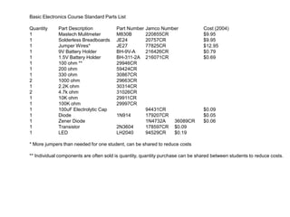
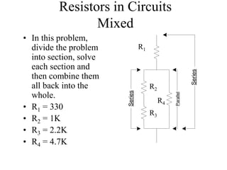
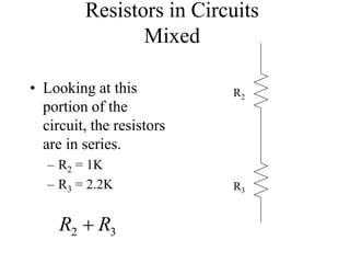
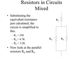
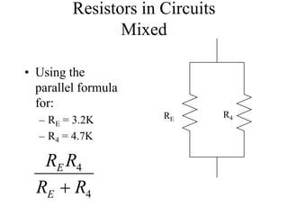
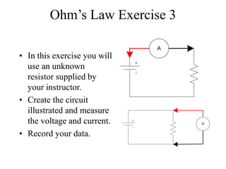
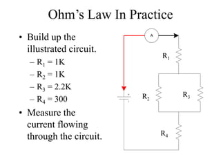
The document provides a parts list and costs for basic electronics components needed for a basic electronics course. It includes multimeters, breadboards, jumper wires, batteries, battery holders, resistors of various ohm values, capacitors, diodes, transistors, and LEDs. The total costs are provided to be around $50 for all components for one student. It is noted that components can be shared between students to reduce costs.
The iot academy_embeddedsystems_training_basicelectronicspart1The IOT Academy
The document provides an overview of basic electronics concepts including:
- The components of electricity such as voltage, current, and resistance.
- How to use a volt-ohm-meter to measure voltage, current, and resistance. Safety precautions are discussed.
- Circuit diagrams and the symbols used to represent common electronic components like resistors, capacitors, diodes, and transistors.
- Resistors including how resistance is defined, resistor color codes to determine resistance values, and how resistors function in series and parallel circuits.
This document provides an introduction to basic electronics concepts including voltage, current, resistance, Ohm's Law, resistors, diodes, LEDs, capacitors, breadboards, and AC/DC power. Key topics covered are voltage measured in volts, current measured in amps, resistance measured in ohms, and their relationship as defined by Ohm's Law. Circuit components such as resistors, diodes, LEDs, and capacitors are explained along with their schematic symbols and uses. Breadboards and prototyping are also discussed.
This document provides an introduction to basic electronics concepts including electricity, voltage, current, resistance, LEDs, Ohm's law, and capacitors. It covers the following key points in 3 sentences:
The document defines basic concepts of electricity including how electrons flow in conductors to create currents, and defines voltage and current. It explains how voltage, current, and resistance are related by Ohm's law and how to measure these quantities using a multimeter. Various circuit components such as LEDs, resistors, capacitors, and breadboards are introduced along with exercises to apply concepts of series and parallel circuits.
This document discusses different types of meters used to measure electrical properties. It describes how ammeters are used to measure current by being connected in series with a circuit. Voltmeters are used to measure voltage by being connected in parallel as they have a high internal resistance. There are different types of ammeters and voltmeters classified by their construction and whether they measure AC or DC. The document also discusses ohmmeters which are used to measure resistance and can have different configurations like series or shunt ohmmeters.
A multimeter is a device used to measure voltage, resistance, and current in electrical equipment. It has two types of displays: analog with a needle and digital with an LCD screen. A multimeter uses its probes and tips to make connections to circuits and uses dial settings and a display to show measurement values for functions like voltage, current, resistance, continuity and more. It works by using a moving coil galvanometer circuit that is converted for different measurement modes.
The document describes the components and operation of a multimeter. It has a moving coil galvanometer with a coil that rotates in a magnetic field. To measure high voltages, a high resistance is connected in series. AC voltage is rectified before reaching the galvanometer. A shunt resistance converts it to an ammeter. Resistance is measured using an internal battery and adjustable resistance. Electrodynamic instruments have high accuracy for AC and DC measurements. They have fixed and moving coils and use springs or weights for control and air damping. Wattmeters use the moving coil to indicate voltage and fixed coils in series with the load to indicate current. Errors can occur due to coil inductance/capacitance and stray magnetic fields. Three
Electrical circuits have basic components like switches, loads, hot and neutral wires. Voltage is electrical pressure that can be alternating current (AC) or direct current (DC), while current is the flow of electrons measured in amps. Resistance is a component's opposition to current flow and is measured in ohms. Common electrical measurements include voltage, current, resistance, frequency, and temperature. Digital multimeters are typically used to measure these components and ensure circuits are functioning properly.
A multimeter is a device used to measure voltage, resistance, and current in electronics and electrical equipment. There are two main types: analog, which has a needle display, and digital, which has an LCD screen. A multimeter can measure voltage, resistance, current, and test continuity. It displays measurement values and has controls to select the measurement function and range.
The document discusses the usage of meters, focusing on ammeters and voltmeters. It provides details on:
- What ammeters and voltmeters are used to measure current and voltage respectively. Ammeters are connected in series while voltmeters are connected in parallel.
- The different types of ammeters and voltmeters based on their construction and the type of current they can measure (AC vs DC).
- How ammeters and voltmeters are calibrated using standard resistors, potentiometers, and known voltage values.
- The importance of selecting meters based on factors like accuracy, cost, range, and application. Common applications of ammeters and voltmeters are also outlined.
This document discusses how various electrical measurement instruments are connected into circuits. It explains that a voltmeter is connected in parallel to measure voltage, an ammeter is connected in series to measure current, and a wattmeter uses both series and parallel connections to measure power by determining both current and voltage. An ohmmeter is also discussed, which measures impedance by connecting at each end of a circuit or load. Different types of analog meters like moving iron and moving coil meters are described along with their advantages and disadvantages. Digital meters and how they work are also covered.
HAM RADIO 101 provides an overview of getting started in ham radio. It explains how to obtain a license by studying and passing a test. It then describes some of the activities hams can participate in, such as emergency communications and radio clubs. The document also provides explanations of basic electrical concepts like Ohm's Law and components like resistors, capacitors, and transistors. It includes examples of circuit diagrams and discusses radio wave properties, antenna types, and electrical safety considerations for ham radio operators.
Switchgear and rectifiers are used to control, protect, and isolate electrical equipment. Switchgear includes disconnect switches, fuses, and circuit breakers, and is used to de-energize equipment for work and clear faults. Rectifiers convert alternating current to direct current through processes like half-wave and full-wave rectification. Common types of switchgear and rectifiers include low voltage switchgear, air circuit breakers, single-phase and three-phase rectifiers, which provide functions like electrical protection, isolation from live parts, and switching. Proper maintenance through inspection, testing, and cleaning helps ensure safe and reliable operation.
This document discusses different types of electronic ammeters and voltmeters. It describes the basic components and operating principles of basic ammeters, multirange ammeters, basic voltmeters, multirange voltmeters, electronic voltmeters including vacuum tube voltmeters and transistor voltmeters. Numerical examples are provided to illustrate how to calculate shunt resistances for converting a meter movement into different current ranges for an ammeter and multiplier resistances for extending the voltage range of a voltmeter.
This document provides an overview of power supplies and switched mode power supplies (SMPS). It discusses the basic components and functioning of linear regulated power supplies, including transformers, rectifiers, filters, regulators and dual supplies. It then introduces SMPS, noting their higher efficiency compared to linear supplies. The document explains the basic block diagram and working of SMPS, including input rectification, inverters, output transformers, rectification and filtering. It also discusses feedback loops, topologies, and popular non-isolated SMPS types like boost, buck and buck-boost converters.
Digital and analogue meters are used to measure electrical quantities in circuits. Digital meters convert input signals to pulses and have advantages like being strong, accurate, and easy to read, but batteries need regular replacing and faults can be hard to identify. Analogue meters have a moving element and a linear scale, making them accurate, but they are fragile and expensive. Voltmeters are connected in parallel across a load to measure voltage. Ammeters are connected in series to measure current. Wattmeters simultaneously measure current and voltage to determine power. Ohmmeters are connected across a circuit element to measure its resistance or impedance. Instruments must be properly connected to circuits to obtain accurate readings of electrical quantities.
1. The Kelvin bridge is a modified Wheatstone bridge used to accurately measure low resistances. It accounts for contact resistance by using four-terminal connections.
2. In a Kelvin bridge, the unknown resistance is connected between two potential terminals to directly measure its value, independent of contact resistance at the current terminals.
3. The bridge balances when the galvanometer is connected to a point between the potential terminals that divides the lead resistance into two equal parts, nullifying its effect on the measurement.
This document discusses different types of basic electrical measuring instruments. It describes absolute instruments, like tangent galvanometers, which directly measure electrical quantities without needing calibration. Secondary instruments require calibration against a standard, examples being multimeters, clamp meters, ammeters and voltmeters. Multimeters are described in detail, including their display, selection knob and ports. The document explains how to use a multimeter to measure AC voltage, DC voltage, resistance, current and test continuity. Clamp meters and the working of ammeters and voltmeters are also briefly covered.
The document discusses various types of electrical test equipment used to test circuits and electrical components. It describes multimeters, megohmmeters, low-resistance ohmmeters, hipotential test sets, high current test sets, secondary test sets, relay test sets, power factor test sets, winding resistance test sets, current transformer test sets, ground resistance test sets, and power recorders. The document provides details on what each type of test equipment is used for and how measurements are made.
This document provides an overview of basic electricity and reading schematics for appliance repair. It covers safety, fundamentals of voltage, current and resistance, electrical symbols and terminology. The document outlines key topics like circuit fundamentals for series, parallel and combination circuits. It also discusses electrical components, instruments for measurement, tips for troubleshooting, and the importance of reading schematics. Troubleshooting common versus complex problems is addressed. Sample schematics are provided for appliances like dryers, washers, ranges and refrigerators.
The document discusses different types of voltmeters including direct coupled DC voltmeters, chopper type DC voltmeters, solid state DC voltmeters, and AC voltmeters using rectifiers. Direct coupled DC voltmeters use cascaded transistors for amplification but have limited range due to gain. Chopper type voltmeters convert DC to AC using a modulator and demodulator to allow for higher sensitivity measurements down to microvolts. Solid state voltmeters use op-amps and feedback to adjust gain while diodes provide overvoltage protection. AC voltmeters use a bridge rectifier and meter movement to indicate the RMS value of an AC input signal.
The document discusses different types of electrical instruments used to measure voltage, current, and resistance. It focuses on multimeters and their components and uses. It also describes other measurement devices like galvanometers, ammeters, voltmeters, and ohmmeters.
Specifically, it defines a multimeter as an electronic instrument that can measure voltage, current, and resistance. It discusses the basic components and types of multimeters, including analog and digital varieties. The document also explains how galvanometers, ammeters, voltmeters, and ohmmeters work by describing their components, circuit configurations, and measurement principles.
1) An electric circuit is a complete path that allows electric current to flow. A battery acts as a pump to push current through the circuit.
2) There are two basic types of circuits: series circuits where current flows through components one after another, and parallel circuits where current divides among branches.
3) Circuit diagrams use symbols to represent components and show connections using straight lines meeting at right angles. Voltmeters measure voltage in parallel, ammeters measure current in series. Fuses and circuit breakers prevent overloading.
This document provides an overview of the key components and functioning of a typical power supply that converts 230V AC household voltage to 12V DC. It describes how the AC voltage passes through a filter, then a transformer that steps it down, before being rectified and filtered to produce a pulsating DC signal. Finally, a regulator circuit stabilizes the output to produce a steady 12V DC power source required by many electronic devices.
To understand the basic working principle of a transformer.
To obtain the equivalent circuit parameters from Open circuit and Short circuit tests, and to estimate efficiency & regulation at various loads.
Form 3 PMR Science Chapter 7 ElectricitySook Yen Wong
This document discusses electricity generation and electric circuits. It describes how chemical cells, lead acid accumulators, bicycle dynamos, and solar cells can generate electricity from chemical, mechanical, and light energy. It defines electric current as the flow of electrons along a conductor and explains how batteries provide voltage or potential difference to cause electron flow. Ammeters and voltmeters are introduced as devices to measure current and voltage. Series and parallel circuits are compared in terms of how components are connected and how they function. Resistance is described as opposing electron flow and factors that influence resistance like material, length, and thickness are outlined. Ohm's law relating current, voltage and resistance is also mentioned.
Chapter wise All Notes of First year Basic Civil Engineering.pptxDenish Jangid
Chapter wise All Notes of First year Basic Civil Engineering
Syllabus
Chapter-1
Introduction to objective, scope and outcome the subject
Chapter 2
Introduction: Scope and Specialization of Civil Engineering, Role of civil Engineer in Society, Impact of infrastructural development on economy of country.
Chapter 3
Surveying: Object Principles & Types of Surveying; Site Plans, Plans & Maps; Scales & Unit of different Measurements.
Linear Measurements: Instruments used. Linear Measurement by Tape, Ranging out Survey Lines and overcoming Obstructions; Measurements on sloping ground; Tape corrections, conventional symbols. Angular Measurements: Instruments used; Introduction to Compass Surveying, Bearings and Longitude & Latitude of a Line, Introduction to total station.
Levelling: Instrument used Object of levelling, Methods of levelling in brief, and Contour maps.
Chapter 4
Buildings: Selection of site for Buildings, Layout of Building Plan, Types of buildings, Plinth area, carpet area, floor space index, Introduction to building byelaws, concept of sun light & ventilation. Components of Buildings & their functions, Basic concept of R.C.C., Introduction to types of foundation
Chapter 5
Transportation: Introduction to Transportation Engineering; Traffic and Road Safety: Types and Characteristics of Various Modes of Transportation; Various Road Traffic Signs, Causes of Accidents and Road Safety Measures.
Chapter 6
Environmental Engineering: Environmental Pollution, Environmental Acts and Regulations, Functional Concepts of Ecology, Basics of Species, Biodiversity, Ecosystem, Hydrological Cycle; Chemical Cycles: Carbon, Nitrogen & Phosphorus; Energy Flow in Ecosystems.
Water Pollution: Water Quality standards, Introduction to Treatment & Disposal of Waste Water. Reuse and Saving of Water, Rain Water Harvesting. Solid Waste Management: Classification of Solid Waste, Collection, Transportation and Disposal of Solid. Recycling of Solid Waste: Energy Recovery, Sanitary Landfill, On-Site Sanitation. Air & Noise Pollution: Primary and Secondary air pollutants, Harmful effects of Air Pollution, Control of Air Pollution. . Noise Pollution Harmful Effects of noise pollution, control of noise pollution, Global warming & Climate Change, Ozone depletion, Greenhouse effect
Text Books:
1. Palancharmy, Basic Civil Engineering, McGraw Hill publishers.
2. Satheesh Gopi, Basic Civil Engineering, Pearson Publishers.
3. Ketki Rangwala Dalal, Essentials of Civil Engineering, Charotar Publishing House.
4. BCP, Surveying volume 1
Gender and Mental Health - Counselling and Family Therapy Applications and In...PsychoTech Services
A proprietary approach developed by bringing together the best of learning theories from Psychology, design principles from the world of visualization, and pedagogical methods from over a decade of training experience, that enables you to: Learn better, faster!
THE SACRIFICE HOW PRO-PALESTINE PROTESTS STUDENTS ARE SACRIFICING TO CHANGE T...indexPub
The recent surge in pro-Palestine student activism has prompted significant responses from universities, ranging from negotiations and divestment commitments to increased transparency about investments in companies supporting the war on Gaza. This activism has led to the cessation of student encampments but also highlighted the substantial sacrifices made by students, including academic disruptions and personal risks. The primary drivers of these protests are poor university administration, lack of transparency, and inadequate communication between officials and students. This study examines the profound emotional, psychological, and professional impacts on students engaged in pro-Palestine protests, focusing on Generation Z's (Gen-Z) activism dynamics. This paper explores the significant sacrifices made by these students and even the professors supporting the pro-Palestine movement, with a focus on recent global movements. Through an in-depth analysis of printed and electronic media, the study examines the impacts of these sacrifices on the academic and personal lives of those involved. The paper highlights examples from various universities, demonstrating student activism's long-term and short-term effects, including disciplinary actions, social backlash, and career implications. The researchers also explore the broader implications of student sacrifices. The findings reveal that these sacrifices are driven by a profound commitment to justice and human rights, and are influenced by the increasing availability of information, peer interactions, and personal convictions. The study also discusses the broader implications of this activism, comparing it to historical precedents and assessing its potential to influence policy and public opinion. The emotional and psychological toll on student activists is significant, but their sense of purpose and community support mitigates some of these challenges. However, the researchers call for acknowledging the broader Impact of these sacrifices on the future global movement of FreePalestine.
This presentation was provided by Racquel Jemison, Ph.D., Christina MacLaughlin, Ph.D., and Paulomi Majumder. Ph.D., all of the American Chemical Society, for the second session of NISO's 2024 Training Series "DEIA in the Scholarly Landscape." Session Two: 'Expanding Pathways to Publishing Careers,' was held June 13, 2024.
Leveraging Generative AI to Drive Nonprofit InnovationTechSoup
In this webinar, participants learned how to utilize Generative AI to streamline operations and elevate member engagement. Amazon Web Service experts provided a customer specific use cases and dived into low/no-code tools that are quick and easy to deploy through Amazon Web Service (AWS.)
Elevate Your Nonprofit's Online Presence_ A Guide to Effective SEO Strategies...TechSoup
Whether you're new to SEO or looking to refine your existing strategies, this webinar will provide you with actionable insights and practical tips to elevate your nonprofit's online presence.
2. Basic Electronics Course Standard Parts List
Quantity Part Description Part Number Jamco Number Cost (2004)
1 Mastech Mulitmeter M830B 220855CR $9.95
1 Solderless Breadboards JE24 20757CR $9.95
1 Jumper Wires* JE27 77825CR $12.95
1 9V Battery Holder BH-9V-A 216426CR $0.79
1 1.5V Battery Holder BH-311-2A 216071CR $0.69
1 100 ohm ** 29946CR
1 200 ohm 59424CR
1 330 ohm 30867CR
2 1000 ohm 29663CR
1 2.2K ohm 30314CR
2 4.7k ohm 31026CR
1 10K ohm 29911CR
1 100K ohm 29997CR
1 100uF Electrolytic Cap 94431CR $0.09
1 Diode 1N914 179207CR $0.05
1 Zener Diode 1N4732A 36089CR $0.06
1 Transistor 2N3604 178597CR $0.09
1 LED LH2040 94529CR $0.19
* More jumpers than needed for one student, can be shared to reduce costs
** Individual components are often sold is quantity, quantity purchase can be shared between students to reduce costs.
3. Basic Electronics for the New Ham
(Outline)
• The Components of Electricity
• Volt-Ohm-Meter Basics (Measuring Electricity)
• Circuit Diagrams Basics (Electronic Roadmaps)
• The Resistor
• Ohm’s Law
• The Capacitor
• The Inductor
• The Diode
• The Transistor (Electronic Valves)
4. The Components of Electricity
• Voltage
• Current
• Resistance
• Types of Current: AC and DC
• Circuits
– Close
– Open
– Short
5. Voltage, Current, and Resistance
• Water flowing through a
hose is a good way to
look at electricity
Water is like Electrons in a wire
(flowing electrons is called
Current)
Pressure is the force pushing water
through a hose – Voltage is the
force pushing electrons
through a wire
Friction against the hole walls
slows the flow of water –
Resistance is the force that
slows the flow of electrons
6. Types of Current
• There are 2 types of current
– The type is determined only by the direction the current
flows through a conductor
• Direct Current (DC)
– Flows in only one direction negative toward positive
pole of source
• Alternating Current (AC)
– Flows back and forth because the poles of the source
alternate between positive and negative
8. Circuits
• A circuit is a path for current to flow
• Three basic kinds of circuits
– Open – the path is broken and interrupts
current flow
– Close – the path is complete and current flows
were it is intended
– Short – the path is corrupted in some way and
current does not flow were it is intended
13. Volt-Ohm-Meter Basics
(Measuring Electricity)
• Measuring voltage
– Voltage type
– Scaling
– Safety
• Physical (personal)
• Equipment
• Measuring current
– Current type
– Scaling
– Safety
• Physical (personal)
• Equipment
• Measuring resistance
– Scaling
14. Measuring voltage
• Voltage type – DC and AC
– When measuring voltage, the meter probes are
placed across the voltage source.
– The VOM uses two separate functions and
ranges to measure DC and AC.
– Because AC is a constantly changing wave
form, measuring AC voltages is not a simple
matter.
– This VOM measures pseudo-RMS voltages
15. Measuring voltage
• Meter Set-up
– Scale set to highest
predictable
– Probes into right
jacks
– Note voltage
polarity
+
16. Measuring Voltage
• Set-up VOM on
600V DC Scale
• Touch red probe to (+)
• Touch black probe to (–)
• Read voltage to
nearest 1 volt
17. Measuring Voltage
• Now touch the red
probe to (-)
• Touch the black probe
to (+)
• Read voltage to nearest
1 volt, note the minus
sign that signifies a
negative voltage
18. Measuring Voltage
• Set-up VOM on 200V
DC Scale
• Touch red probe to (+)
• Touch black probe to (–)
• Read voltage to
nearest .1 volt
19. Measuring Voltage
• Set-up VOM on 20V
DC Scale
• Touch red probe to (+)
• Touch black probe to (–)
• Read voltage to
nearest .01 volt
20. Measuring Voltage
• Set-up VOM on 20V DC
Scale
• Touch red probe to (+)
• Touch black probe to (–)
• Using a 1.5 volt battery -
read voltage to nearest
.01 volt
21. Measuring Voltage
• Set-up VOM on 2000mV
DC Scale
• This scale is reading 2000
milli-volts
(or 2 volts)
• Touch red probe to (+)
• Touch black probe to (–)
• Using a 1.5 volt battery - read
voltage to nearest .001
volt
22. Measuring Voltage
• Set-up VOM on
2000m V DC Scale
• Touch red probe to (+)
• Touch black probe to (–)
• Using a 9 volt battery
• This is clearly an over-
voltage situation, note
the reading.
23. Measuring Voltage - Safety
• When measuring voltage, the voltage being
measured is exposed to the operator and flowing
through the probes. Be cautious, be attentive,
watch what you touch!
• The probes have sharp points so that you can
make precise contacts. Use the protective shields
when probes not in use.
• Observe the meter maximum limits for voltage
and current. Fuses are a last resort protection
feature. If you blow a fuse, you made a mistake!
25. Measuring Current
• There is greatest potential for meter damage when
measuring current than any other function.
• Just as in voltage, there is two kinds of current
associated with the voltage, AC and DC
• This meter will only measure DC, more expensive
meters will measure both currents
• To measure current, the VOM must be inserted
into the circuit so that the current flows through
the meter.
26. Measuring Current
• There are two current ranges, high – up to 10
amps, and low – 200 milliamps (.2 amps) and
below.
• Internal fuses provide some meter protection for
over current situations.
– Because there is such a wide range of current scales,
there are two physical probe jacks for the two ranges
– This allows for better protection, a hardy fuse to handle
up to 10 amps of current and a more fragile fuse to
protect the sensitive circuits needed to measure small
currents.
27. Measuring Current
• CAUTION!!!!!!! There must be some resistance
in the circuit or the current flow through the
circuit will be the maximum the source will
produce, AND THIS CURRENT LEVEL
COULD DAMAGE THE VOM!
• In other words, DO NOT CONNECT THE
VOM PROBES DIRECTLY ACROSS THE
BATTERY POLES IN THE CURRENT
MEASURMENT FUNCTION!
28. Measuring Current
• We will be using some concepts during the
current measurement exercises that will be
covered in more detail later, so be patient, it
will all come together in the end.
• In the following exercises you will use
various resistors to limit the current flow in
a simple circuit.
31. First Current Measurement
• Set up the circuit using a
100 ohm resistor (brown,
black, brown).
• Connect a wire to the +
power source, connect
another wire to the top
end of the resistor (the
non grounded end).
• Set VOM current scale to
200m.
• Without connecting the
battery, practice touching
the VOM probes to the
exposed wire ends.
32. First Current Measurement
• Connect the battery.
• With the VOM set to the
200m current scale, touch
the black lead to the wire
hooked to the high side of
the resistor.
• Touch the red lead to the
lead coming from the +
side of the battery.
• Note the VOM reading.
34. First Current Measurement
• Return the VOM leads so
that the red is connected to
the battery.
• Change the VOM current
ranges down and note the
display readings
• What is the best range for
measuring the current from
a 9 volt source through a
100 ohm resistor?
200m Range
20m Range
35. Measuring Current
• Wire the circuit
with a 1k ohm
resistor (brown,
black, red).
• Measure current
with 200m
range.
36. Measuring Current
• What is the best
range to measure
the current
through a 1 k
resistor?
200m
20m
2000u
37. Measuring Current
• Wire the circuit with
a 10 k ohm resistor
(brown, black,
orange).
• Measure current
with the 2000u
range.
38. Measuring Current
• What is the best
range to use to
measure the
current through
a 10 k ohm
resistor at 9
volts?
2000u
200u
39. Measuring Current
• Wire the circuit
with a 100 k ohm
resistor (brown,
black, yellow).
• Begin with the
2000m range, and
measure the current
at each range.
• What is the best
range to use to
measure the current
trough a 100 k ohm
resistor at 9 volts?
40. Measuring Resistance
• When the VOM is used to measure resistance,
what actually is measured is a small voltage and
current applied to the component.
• There are 5 ranges, an out of resistance reading
will indicate a single 1 digit. Remember k means
multiply the reading by 1000.
• Operating voltages should be removed from the
component under test or you could damage the
VOM at worst, or the reading could be false at
best.
41. Measuring Resistance
• Disconnect the battery
from the board,
remember to measure
resistance the circuit
should be un-powered.
• Put the 100 ohm resistor
in place, no additional
wires are required.
• Select the 200 range and
touch the probe leads to
either side of the
resistor.
43. Measuring Resistance
• Now using the 100 ohm
resistor, measure the
resistance using each of
the other ranges.
• Note that the resolution of
the reading decreases as
the maximum ohm
reading increases, down
to the point where it is
difficult to get a good
resistance reading.
2000
20k
200k
2000k
44. Measuring Resistance
• Now use the 1k ohm
resistor and the 200
range.
• Explain the reading
you observe.
• Find the appropriate
range to measuring
1,000 ohms (1k).
200
2000
45. Measuring Resistance
• Now use the 10k and the 100k resistor.
• First determine the appropriate range to use
for each resistor.
• Second make the resistance measurements
• Third, using higher ranges predict the
reading and confirm your prediction by
taking the measurements
46. Measuring Resistance
• Just for fun, use the VOM to measure the
resistance offered your different body parts.
– The voltage and current used by the VOM is
not dangerous.
• Discuss your observations and how your
measurement techniques could influence the
readings you get from the VOM.
57. The Resistor
• Resistance defined
• Resistance values
– Ohms – color code interpretation
– Power dissipation
• Resistors in circuits
– Series
– Parallel
– Mixed
58. Resistance Defined
• Resistance is the impediment to the free
flow of electrons through a conductor
– (friction to moving electrons)
– Where there’s friction, there is heat generated
– All materials exhibit some resistance, even the
best of conductors
• Unit measured in Ohm(s)
– From 1/10st of Ohms to millions of Ohms
59. Resistor Types
• Fixed Value
• Variable value
• Composite resistive material
• Wire wound
• Two parameter associated with resistors
– Resistance value in Ohms
– Power handling capabilities in watts
64. Reading Resistor Color Codes
1. Turn resistor so gold or silver band is at right
2. Note the color of the two left hand color bands
3. The left most band is the left hand value digit
4. The next band to the right is the second value
digit
5. Note the color of the third band from the left, this
is the multiplier
6. Multiply the 2 value digits by the multiplier
67. Power dissipation
• Resistance generates heat and the
component must be able to dissipate this
heat to prevent damage.
• Physical size (the surface area available to
dissipate heat) is a good indicator of how
much heat (power) a resistor can handle
• Measured in watts
• Common values ¼, ½, 1, 5, 10 etc.
70. Resistors in Circuits
Series
• On your proto board set up
the following circuit using
the resistance values
indicated on the next slide.
• Calculate the equivalent
resistant RE and measure
the resistance with your
VOM
R1
R2
74. Resistors in Circuits
Parallel
• On your proto board
set up the following
circuit using the
resistance values
indicated on the next
slide.
• Calculate the
equivalent resistant
RE and measure the
resistance with your
VOM
R1
R2
76. Resistors in Circuits
Parallel Challenge
• Make a circuit with 3 resistors in parallel,
calculate the equivalent resistance then
measure it.
– R1 = 330
– R2 = 10K
– R3 = 4.7K
77. Resistors in Circuits
Mixed
• If the path for the
current in a portion
of the circuit is a
single path, and in
another portion of
the circuit has
multiple routes, the
circuit is a mix of
series and parallel.
Series
Parallel
Series
R
78. Resistors in Circuits
Mixed
• Let’s start with a
relatively simple
mixed circuit.
Build this using:
– R1 = 330
– R2 = 4.7K
– R3 = 2.2K
R1
R2
R3
79. Resistors in Circuits
Mixed
• Take the parallel
segment of the
circuit and
calculate the
equivalent
resistance:
R1
R2
R3
3
2
3
2
R
R
R
R
80. Resistors in Circuits
Mixed
• We now can look at
the simplified circuit
as shown here, the
parallel resistors have
been replaced by a
single resistor with a
value of 1498 ohms.
• Calculate the
resistance now of this
series circuit:
E
R
R
1
R1
RE=1498
81. Resistors in Circuits
Mixed
• In this problem,
divide the problem
into section, solve
each section and
then combine them
all back into the
whole.
• R1 = 330
• R2 = 1K
• R3 = 2.2K
• R4 = 4.7K
Series
Parallel
Series
R1
R2
R3
R4
82. Resistors in Circuits
Mixed
• Looking at this
portion of the
circuit, the resistors
are in series.
– R2 = 1K
– R3 = 2.2K
R2
R3
3
2 R
R
83. Resistors in Circuits
Mixed
• Substituting the
equivalent resistance
just calculated, the
circuit is simplified to
this.
– R1 = 330
– R4 = 4.7K
– RE = 3.2K
• Now look at the parallel
resistors RE and R4.
R1
RE R4
85. Resistors in Circuits
Mixed
• The final calculations
involve R1 and the new
RE from the previous
parallel calculation.
– R1 = 330
– RE = 1.9K
R1
RE
E
R
R
1
87. Ohm’s Law
• The mathematical relationship
– E=I*R
• Doing the math
• kirchhoff’s Law
– A way to predict circuit behavior
• It all adds up
• Nothing is lost
88. Ohm’s Law
• There is a
mathematical
relationship between
the three components
of electricity. That
relationship is Ohm’s
Law.
– E = volts
– R = resistance in ohms
– I = current in amps
R
I
E *
I
E
R
R
E
I
90. Ohm’s Law
• This is the basic
circuit that you
will use for the
following
exercises.
• The VOM will be
moved to measure
voltage/resistance
and current.
A
V
91. Ohm’s Law Exercise 1
• Wire this circuit
using a 100 ohm
resistor.
• Without power
applied measure the
resistance of the
resistor.
• Connect the 9 volt
battery and measure
the voltage across the
resistor.
• Record your data.
V
92. Ohm’s Law Exercise 1
• Using the voltage
and resistance data
in Ohm’s Law,
calculate the
anticipated current.
• Example data
results in a current
of .09 amps or 90
milli-amps
R
E
I
ohms
volts
amps
1
.
98
8
.
8
09
.
93. Ohm’s Law Exercise 1
• Insert the VOM into the
circuit as indicated in
this diagram.
• Using the appropriate
current range, measure
the actual current in the
circuit.
• How does the current
compare to your
prediction using Ohm’s
Law?
A
94. Ohm’s Law Exercise 2
• Select the 1K ohm
resistor and create the
illustrated circuit.
• Pretend for this exercise
that you do not know
what the voltage of the
battery is.
• Measure the resistance
with power removed and
then the current with
power.
• Record your data.
A
95. Ohm’s Law Exercise 2
• Using the current and
resistance data in
Ohm’s Law, calculate
the anticipated
voltage.
• Example data results
in a voltage of 9.73
volts
R
I
E *
96. Ohm’s Law Exercise 2
• Connect the VOM
into the circuit as
indicated in this
diagram.
• Using the appropriate
voltage range,
measure the actual
voltage across the
resistor.
• How does the current
compare to your
prediction using
Ohm’s Law?
V
97. Ohm’s Law Exercise 3
• In this exercise you will
use an unknown
resistor supplied by
your instructor.
• Create the circuit
illustrated and measure
the voltage and current.
• Record your data.
V
A
98. Ohm’s Law Exercise 3
• Using the voltage and
current data in Ohm’s
Law, calculate the
unknown resistance.
• Example data results in
a resistance of 3844
ohms. I
E
R
99. Ohm’s Law In Practice
• The next series of exercises will put Ohm’s Law to
use to illustrate some principles of basic
electronics.
• As in the previous exercise you will build the
circuits and insert the VOM into the circuit in the
appropriate way to make current and voltage
measurements.
• Throughout the exercise record your data so that
you can compare it to calculations.
100. Ohm’s Law In Practice
• Build up the
illustrated circuit.
– R1 = 1K
– R2 = 1K
– R3 = 2.2K
– R4 = 300
• Measure the
current flowing
through the circuit.
R1
R2
R3
R4
A
101. Ohm’s Law In Practice
• Now move the VOM
to the other side of
the circuit and
measure the current.
• The current should be
the same as the
previous
measurement.
A
102. Ohm’s Law In Practice
• Insert the VOM
at the indicated
location and
measure the
current.
• There should be
no surprise that
the current is the
same.
A
103. Ohm’s Law In Practice
• Measure the voltage
across R1.
• Using Ohm’s law,
calculate the voltage
drop across a 1K
ohm resistor at the
current you
measured
• Compare the result.
V
104. Ohm’s Law In Practice
• In this next step, you
will insert the VOM
in the circuit at two
places illustrated at
the right as #1 and #2.
• Record your current
readings for both
places.
• Add the currents and
compare and contrast
to the current
measured entering the
total circuit.
A A
#1 #2
105. Ohm’s Law In Practice
• Using the current measured through #1 and the
resistance value of R2, 1k ohms, calculate the
voltage drop across the resistor.
• Likewise do the same with the current measured
through #2 and the resistance value of R3, 2.2k
ohms.
• Compare and contrast these two voltage values
106. Ohm’s Law In Practice
• Measure the voltage
across the parallel
resistors and record
your answer.
• Compare and contrast
the voltage measured
to the voltage drop
calculated.
V
107. Ohm’s Law In Practice
• In the next step, insert
the VOM into the
circuit as illustrated,
measure and record the
current.
• Compare and contrast
the current measured to
the total current
measured in a previous
step.
• Were there any
surprises?
A
108. Ohm’s Law In Practice
• Using the current you
just measured and the
resistance of R4 (330
ohms), calculate what
the voltage drop across
R4 should be.
• Insert the VOM into
the circuit as illustrated
and measure the
voltage.
• Compare and contrast
the measured and
calculated voltages.
V
109. Ohm’s Law In Practice
• There is one final
measurement to complete
this portion of the exercise.
Insert the VOM as
indicated.
• Recall the 3 voltages
measured previously; across
R1, R2 and R3, and across
R4.
• Add these three voltages
together and then compare
and contrast the result with
the total voltage just
measured.
V
110. Ohm’s Law In Practice
• What you observed was:
– The sum of the individual currents was equal to
the total current flowing through the circuit.
– The sum of the voltage drops was equal to the
total voltage across the circuit.
• This is Kirchhoff’s Law and is very useful
in the study of electronic circuit.
• You also noted that Ohm’s Law applied
throughout the circuit.
111. The Capacitor
• Capacitance defined
• Physical construction
– Types
– How construction
affects values
– Power ratings
• Capacitor performance
with AC and DC
currents
• Capacitance values
– Numbering system
• Capacitors in circuits
– Series
– Parallel
– Mixed
113. The Capacitor
Defined
• A device that stores energy
in electric field.
• Two conductive plates
separated by a non
conductive material.
• Electrons accumulate on one
plate forcing electrons away
from the other plate leaving
a net positive charge.
• Think of a capacitor as very
small, temporary storage
battery.
114. The Capacitor
Physical Construction
• Capacitors are rated
by:
– Amount of charge
that can be held.
– The voltage handling
capabilities.
– Insulating material
between plates.
115. The Capacitor
Ability to Hold a Charge
• Ability to hold a charge
depends on:
– Conductive plate
surface area.
– Space between plates.
– Material between plates.
117. Charging a Capacitor
• In the following activity you
will charge a capacitor by
connecting a power source (9
volt battery) to a capacitor.
• You will be using an electrolytic
capacitor, a capacitor that uses
polarity sensitive insulating
material between the conductive
plates to increase charge
capability in a small physical
package.
• Notice the component has
polarity identification + or -.
+
118. Charging a Capacitor
• Touch the two leads of the capacitor
together.
• This short circuits the capacitor to make
sure there is no residual charge left in the
capacitor.
• Using your VOM, measure the voltage
across the leads of the capacitor
119. Charging a Capacitor
• Wire up the circuit illustrated
and charge the capacitor.
• Power will only have to be
applied for a moment to fully
charge the capacitor.
• Quickly remove the capacitor
from the circuit and touch the
VOM probes to the capacitor
leads to measure the voltage.
• Carefully observe the voltage
reading over time until the
voltage is at a very low level
(down to zero volts).
+
121. The Capacitor
Behavior in DC
• When exposed to DC, the capacitor charges
and holds the charge as long as the DC
voltage is applied.
• The capacitor essentially blocks DC voltage
from passing through.
122. The Capacitor
Behavior in AC
• When AC current is applied, during one half of the
cycle the capacitor accepts a charge in one
direction.
• During the next half of the cycle, the capacitor is
discharges then recharged in the reverse direction.
• During the next half cycle the pattern reverses.
• Essentially, it appears that AC current passes
through a capacitor
124. The Capacitor
Capacitance Value
• The unit of capacitance is the farad.
– A single farad is a huge amount of capacitance.
– Most electronic devices use capacitors that have
a very tiny fraction of a farad.
• Common capacitance ranges are:
– Micro - 10-6
– Nano - 10-9
– Pico - 10-12
p
n
125. The Capacitor
Capacitance Value
• Capacitor identification
depends on the capacitor
type.
• Could be color bands, dots,
or numbers.
• Wise to keep capacitors
organized and identified to
prevent a lot of work trying
to re-identify the values.
126. Capacitors in Circuits
• Two physical
factors affect
capacitance values.
– Plate spacing
– Plate surface area
• In series, plates are
far apart making
capacitance less
2
1
2
1
C
C
C
C
+
-
Charged plates
far apart
127. Capacitors in Circuits
• In parallel, the
surface area of the
plates add up to be
greater, and close
together.
• This makes the
capacitance more the
Capacitor
2
1 C
C
+
-
128. The Inductor
• Inductance defined
• Physical construction
– How construction
affects values
• Inductor performance
with AC and DC
currents
129. The Inductor
• There are two fundamental principles of
electronics:
1. Moving electrons create a magnetic field.
2. Moving or changing magnetic fields cause
electrons to move.
• An inductor is a coil of wire through
which electrons move, and energy is
stored in the resulting magnetic field.
130. The Inductor
• Like capacitors,
inductors temporarily
store energy.
• Unlike capacitors:
– Inductors store energy in
a magnetic field, not an
electric field.
– When the source of
electrons is removed, the
magnetic field collapses
immediately.
131. The Inductor
• Inductors are simply
coils of wire.
– Can be air wound
(nothing in the middle
of the coil)
– Can be wound around a
permeable material
(material that
concentrates magnetic
fields)
– Can be wound around a
circular form (toroid)
132. The Inductor
• Inductance is measured in Henry(s).
• A Henry is a measure of the intensity of the
magnetic field that is produced.
• Typical inductor values used in electronics
are in the range of milli Henry (1/1000) and
micro Henry (1/1,000,000)
133. The Inductor
• The amount of
inductance is
influenced by a
number of factors:
– Number of coil turns.
– Diameter of coil.
– Spacing between
turns.
– Size of the wire used.
– Type of material
inside the coil.
134. Inductor Performance With DC
Currents
• When DC current is applied to an inductor, the wire in the
inductor momentarily appears as a short circuit and
maximum current flows.
• As the magnetic field builds (changes) there is a tendency
for the current flow to slow down (due to an opposition
cause the the changing magnetic field).
• Finally, the magnetic field is at its maximum and the
current flows to maintain the field.
• As soon as the current source is removed, the magnetic
field begins to collapse and creates a rush of current in the
other direction, sometimes at very high voltages.
135. Inductor Performance With AC
Currents
• When AC current is applied to an inductor, during
the first half of the cycle, the magnetic field builds
as if it were a DC voltage.
• During the next half of the cycle, the current is
reversed and the magnetic field first has to
decrease the reverse polarity in step with the
changing current.
• Depending on the value of inductance, these
forces can work against each other, making for a
less than simple situation.
136. The Inductor
• Because the magnetic
field surrounding an
inductor can cut across
another inductor in
close proximity, the
changing magnetic
field in one can cause
current to flow in the
other … the basis of
transformers
137. The Diode
• The semi-conductor phenomena
• Diode performance with AC and DC
currents
• Diode types
– Basic
– LED
– Zenier
138. The Diode
The semi-conductor phenomena
• Electrons in a metal form a “sea” of
electrons that are relatively fee to move
about.
• Semiconducting materials like Silicon and
Germanium have fewer free electrons.
• Impurities added to semiconductor material
can either add free electrons or create an
absence of electrons (holes).
139. The Diode
The semi-conductor phenomena
• Consider the bar of silicon at the right.
– One side of the bar is doped with negative material
(excess electrons). The cathode.
– The other side is doped with positive material
(excess holes). The anode
– In between is a no man’s land called the P-N
Junction.
140. The Diode
The semi-conductor phenomena
• Consider now applying a negative voltage
to the anode and positive voltage to the
cathode.
• This diode is reverse biased meaning no
current will flow.
141. The Diode
The semi-conductor phenomena
• Consider now applying a positive voltage to
the anode and a negative voltage to the
cathode.
• This diode is forward biased meaning
current will flow.
142. The Diode
• Set up the circuit
illustrated on the proto
board.
• Ensure to note the
cathode (banded end)
of the diode.
• Use a 330 ohm resistor.
The resistor in the
circuit is a current
limiting resistor.
A
330
143. The Diode
• Set up the circuit
illustrated on the
proto board
(reverse the diode).
• Ensure to note the
cathode (banded
end) of the diode.
A
144. The Diode
• Build the illustrated
circuit.
• Measure the voltage
drop across the
diode that is forward
biased.
V
145. The Diode
with AC Current
• If AC is applied to a diode:
– During one half of the cycle the diode is
forward biased and current flows.
– During the other half of the cycle, the diode is
reversed biased and current stops.
• This is the process of rectification, allowing
current to flow in only one direction.
• i.e., changing AC into DC
146. The Diode
with AC Current
Input AC
Output
Pulsed DC
Diode
conducts
Diode off
147. The Light Emitting Diode
• In normal diodes, when electrons combine
with holes heat is produced.
• With some materials, when electrons
combine with holes, photons of light are
emitted.
• LEDs are generally used as indicators
though they have the same properties as a
regular diode.
148. The Light Emitting Diode
• Build the illustrated
circuit on the proto
board.
• The longer LED lead is
the anode (positive end).
• Then reverse the LED
and observe what
happens.
• The current limiting
resistor not only limits
the current but also
controls LED
brightness.
330
149. Zener Diode
• A Zener diode is
designed through
appropriate doping so
that it conducts at a
predetermined reverse
voltage.
– The diode begins to
conduct and then
maintains that
predetermined voltage
• The over-voltage and
associated current must
be dissipated by the
diode as heat
9V 4.7V
150. The Transistor
(Electronic Valves)
• How they works, an inside look
• Basic types
– NPN
– PNP
• The basic transistor circuits
– Switch
– Amplifier
152. The Transistor
N P N
collector emitter
base e -
e -
forward bias
conducting
e -
153. The Transistor
N P N
collector emitter
base e -
e -
reverse bias
no-conducting
154. The Transistor
• There are two basic types of
transistors depending of the
arrangement of the material.
– PNP
– NPN
• An easy phrase to help remember
the appropriate symbol is to look
at the arrow.
– PNP – pointing in proudly.
– NPN – not pointing in.
• The only operational difference is
the source polarity.
PNP
NPN
155. The Transistor Switch
• During the next two
activities you will
build a transistor
switch and a
transistor amplifier.
• The pin out of the
2N3904 transistor is
indicated here.
C
B
E
156. The Transistor Switch
• Build the circuit on the
proto board.
• Use hook up wire to
serve as “switches” to
connect the current to
the transistor base.
• What happens when you
first apply power when
the base is left floating
(not connected)?
330
1000
157. The Transistor Switch
• Make the illustrated
adjustment to the circuit.
• Connect one end of
some hook-up wire to
the positive side of the 9
volt battery.
• Touch the other end
(supply 9 volts) to the
resistor in the base line
and observe what
happens.
330
1000
158. The Transistor Switch
• Now replace the hook-up
wire connection with a
connection to a 1.5 volt
battery as shown.
• What happens when +1.5
volts is applied to the
base?
• What happens when the
battery is reversed and –
1.5 volts is applied to the
base?
330
1000
1.5V
9V
159. The Transistor Switch
• When does the
transistor start to
turn on?
• Build up the
illustrated circuit
with the variable
resistor in the base
circuit to find out.
330
1000
9V
161. Conclusion
• Not really - your journey to understand
basic electronics has just begun.
• This course was intended to introduce you
to some concepts and help you become
knowledgeable in others.