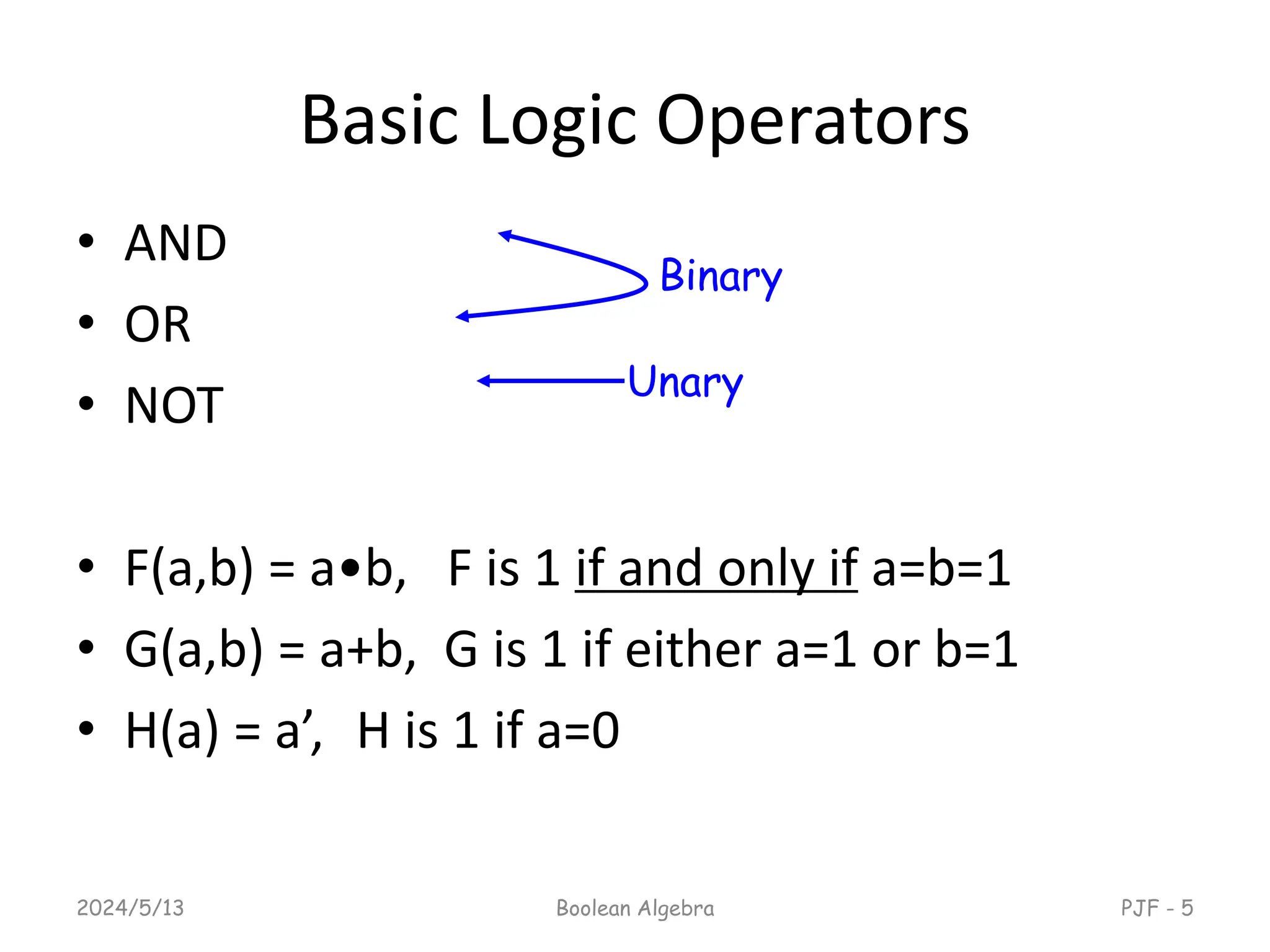
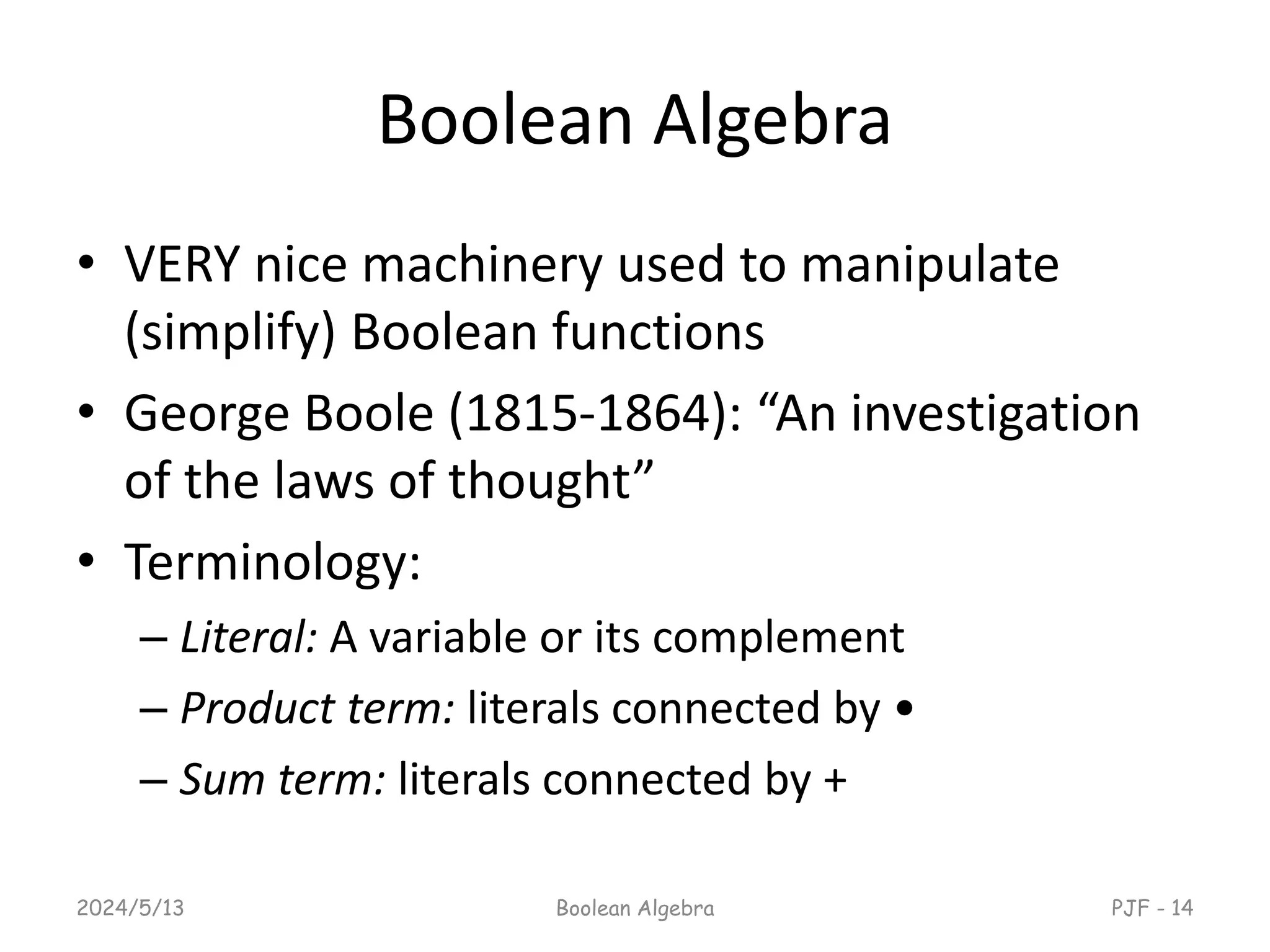
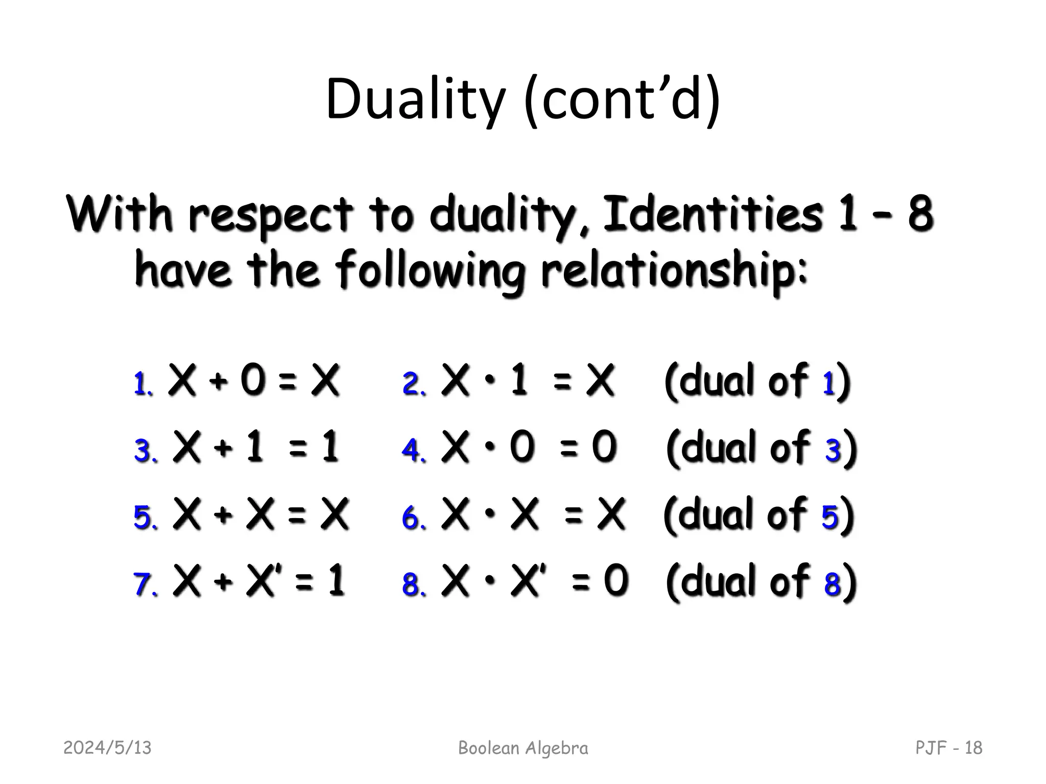
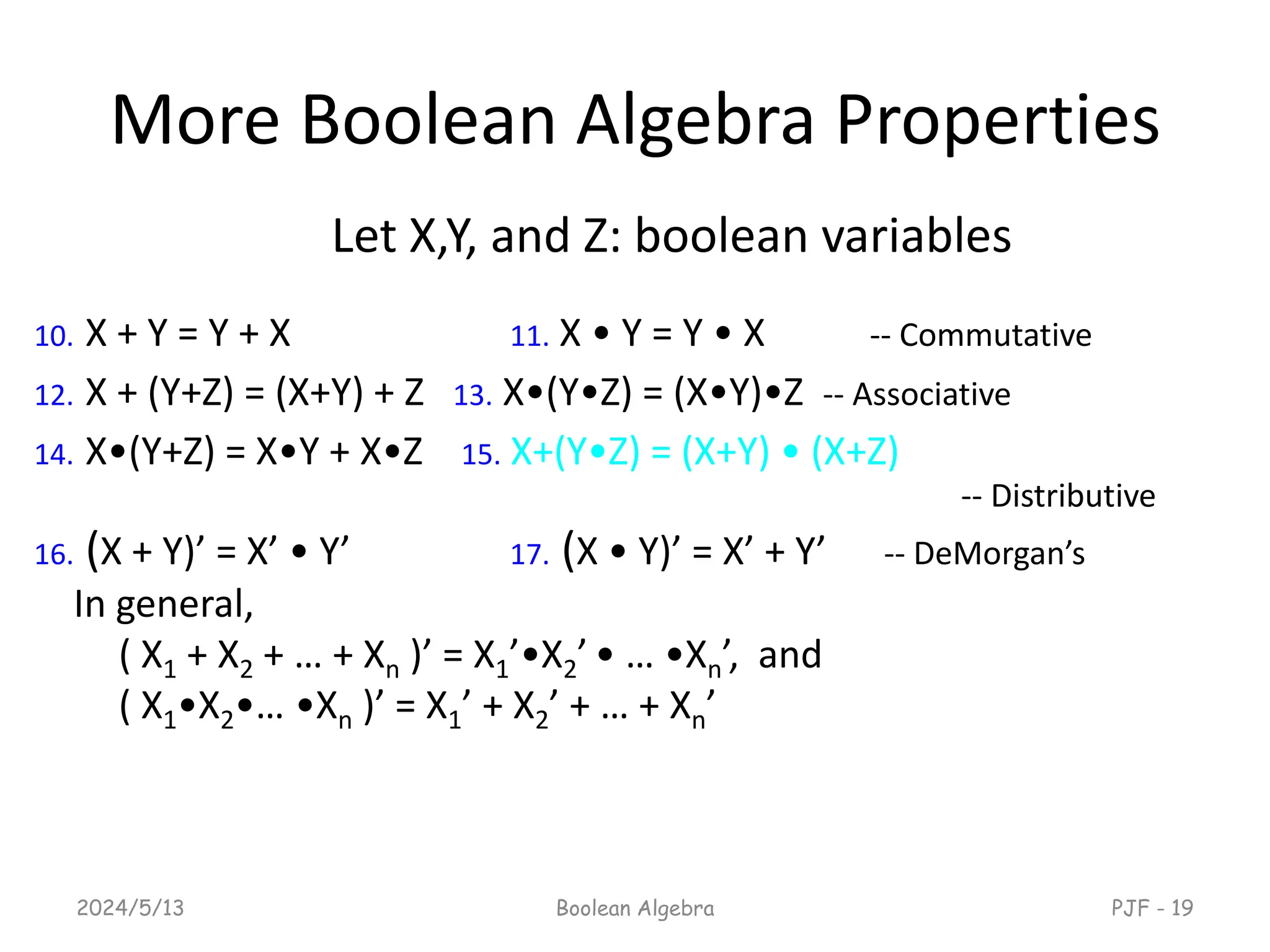
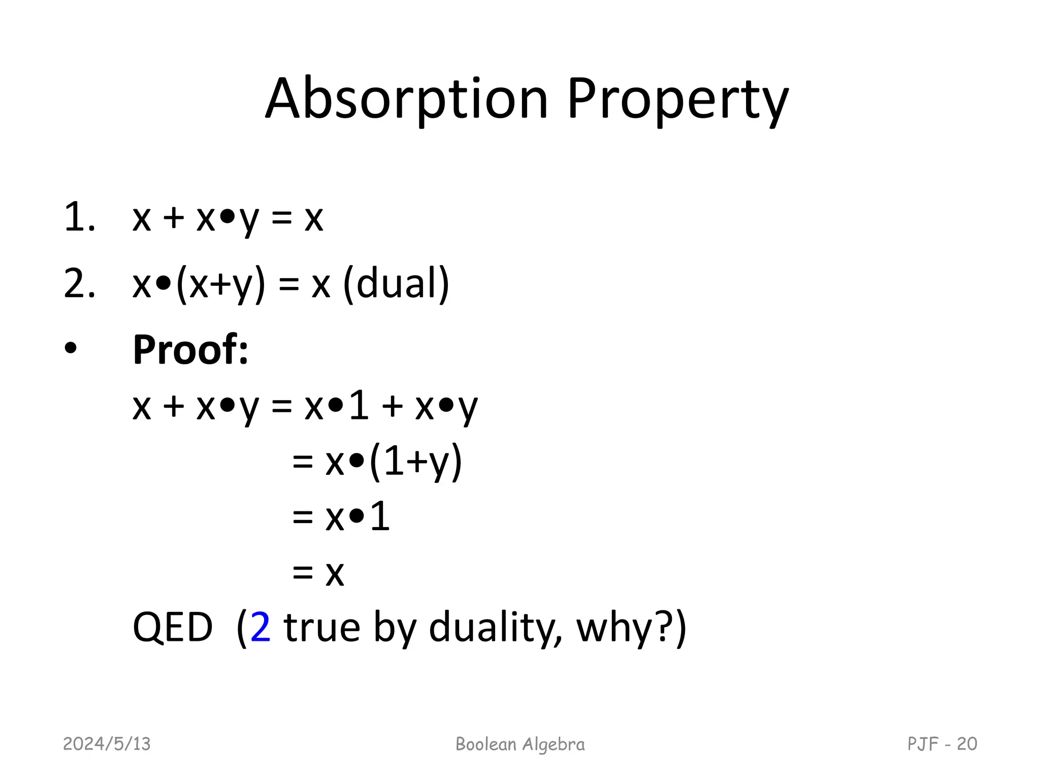
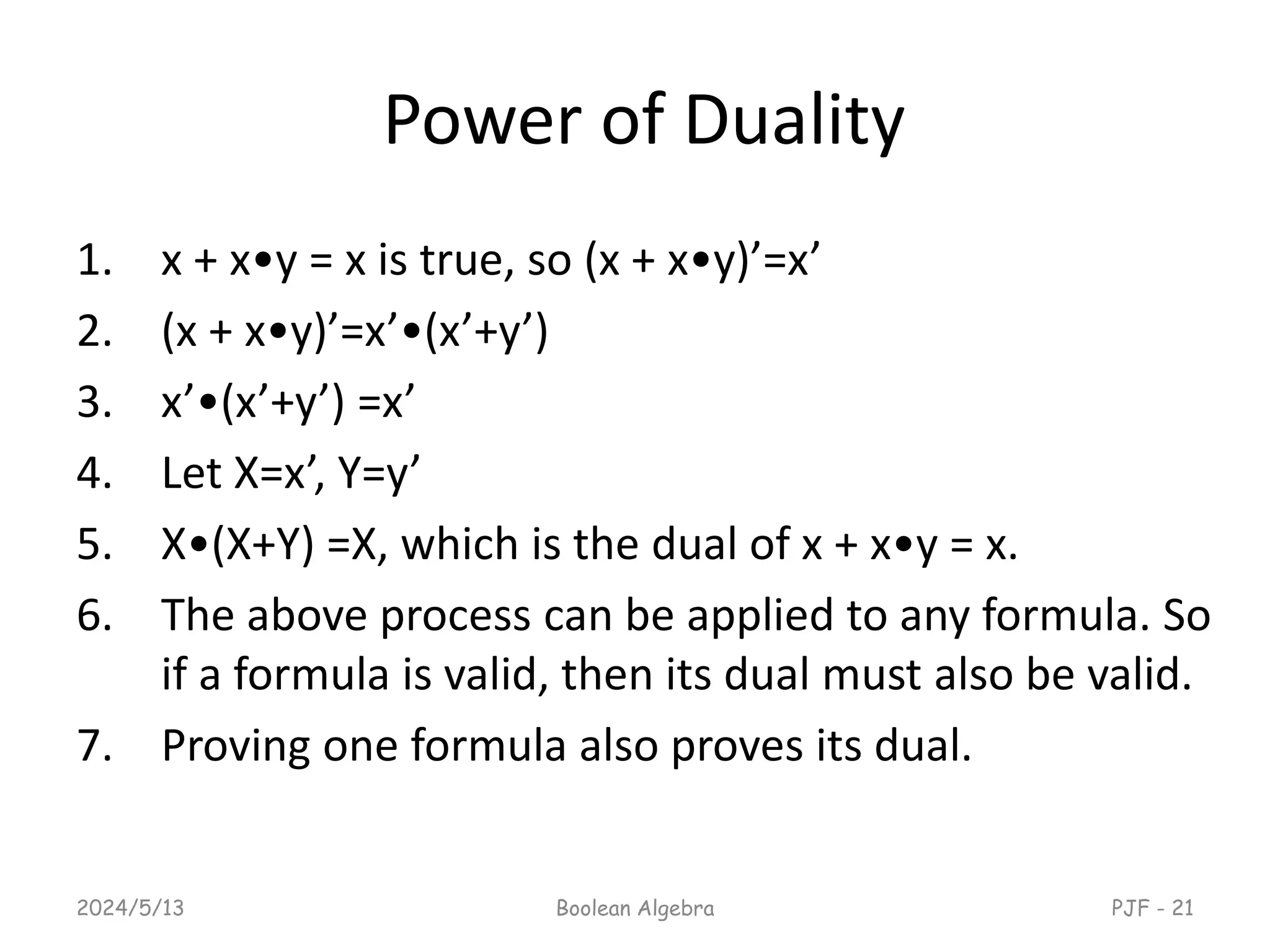
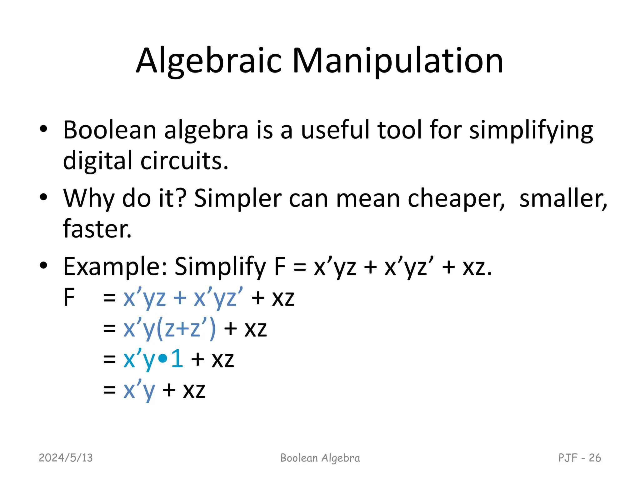
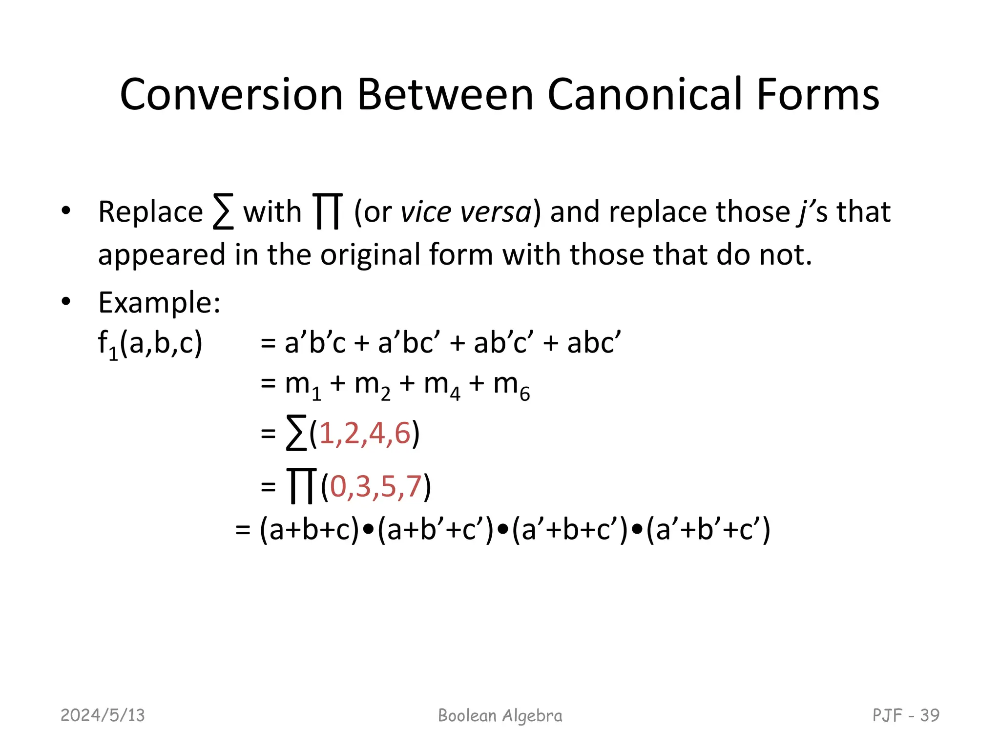
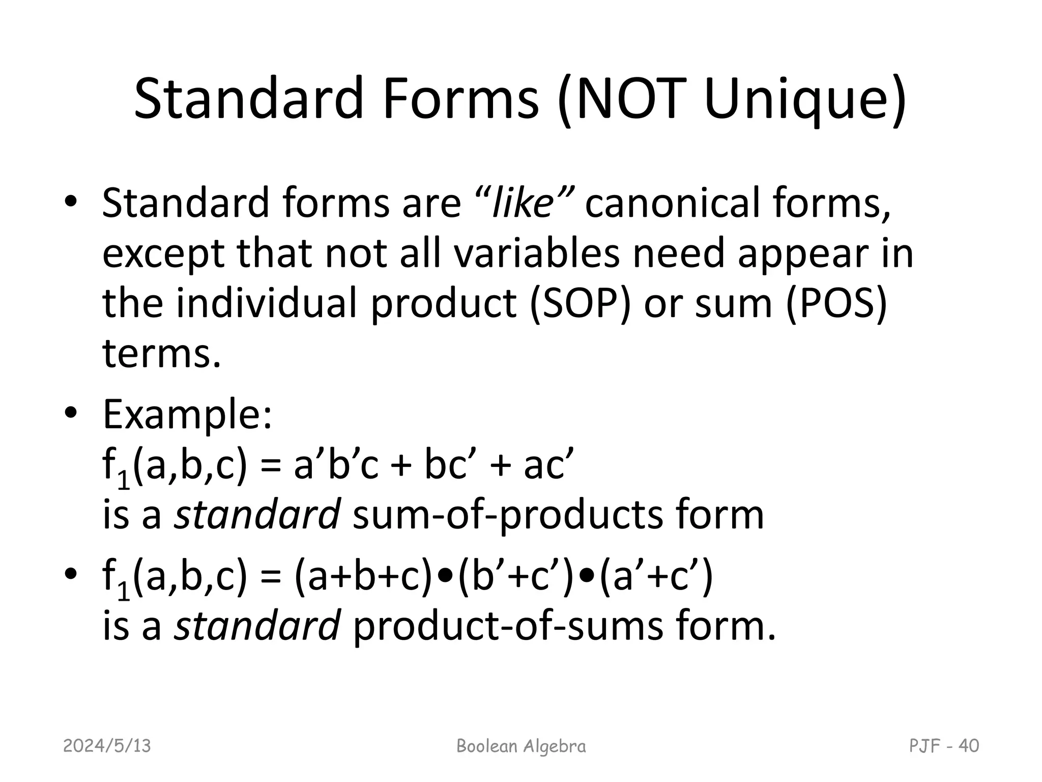
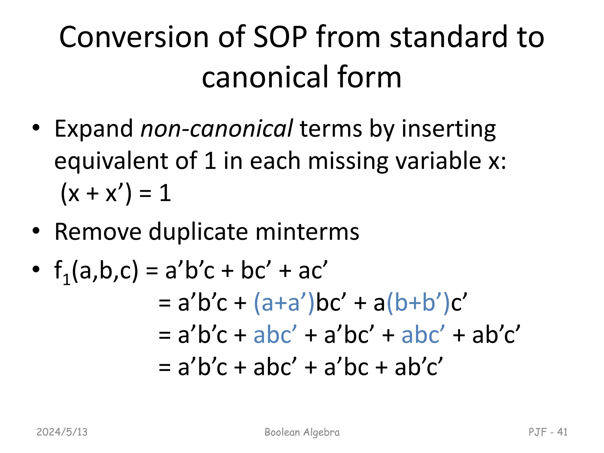
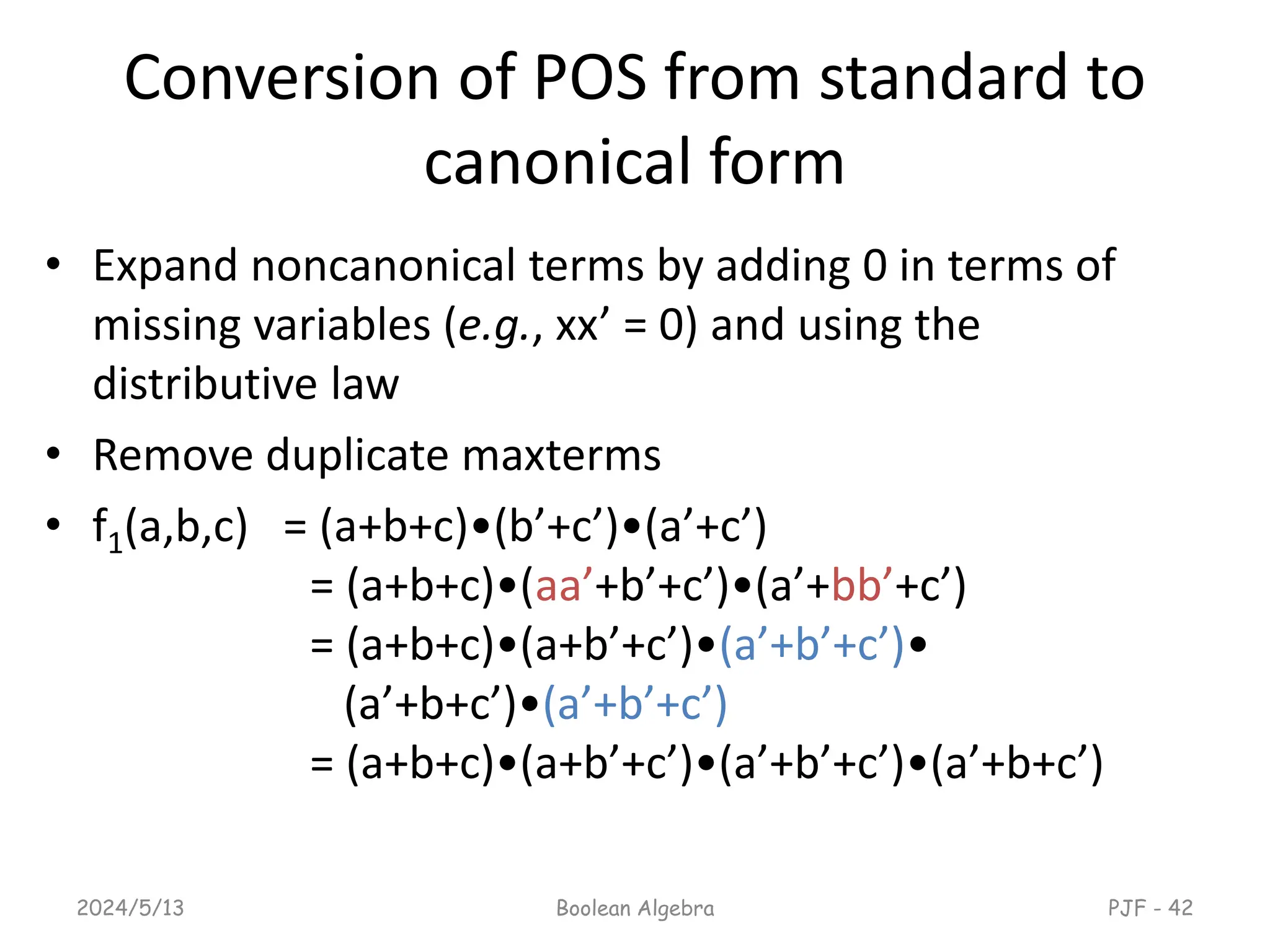
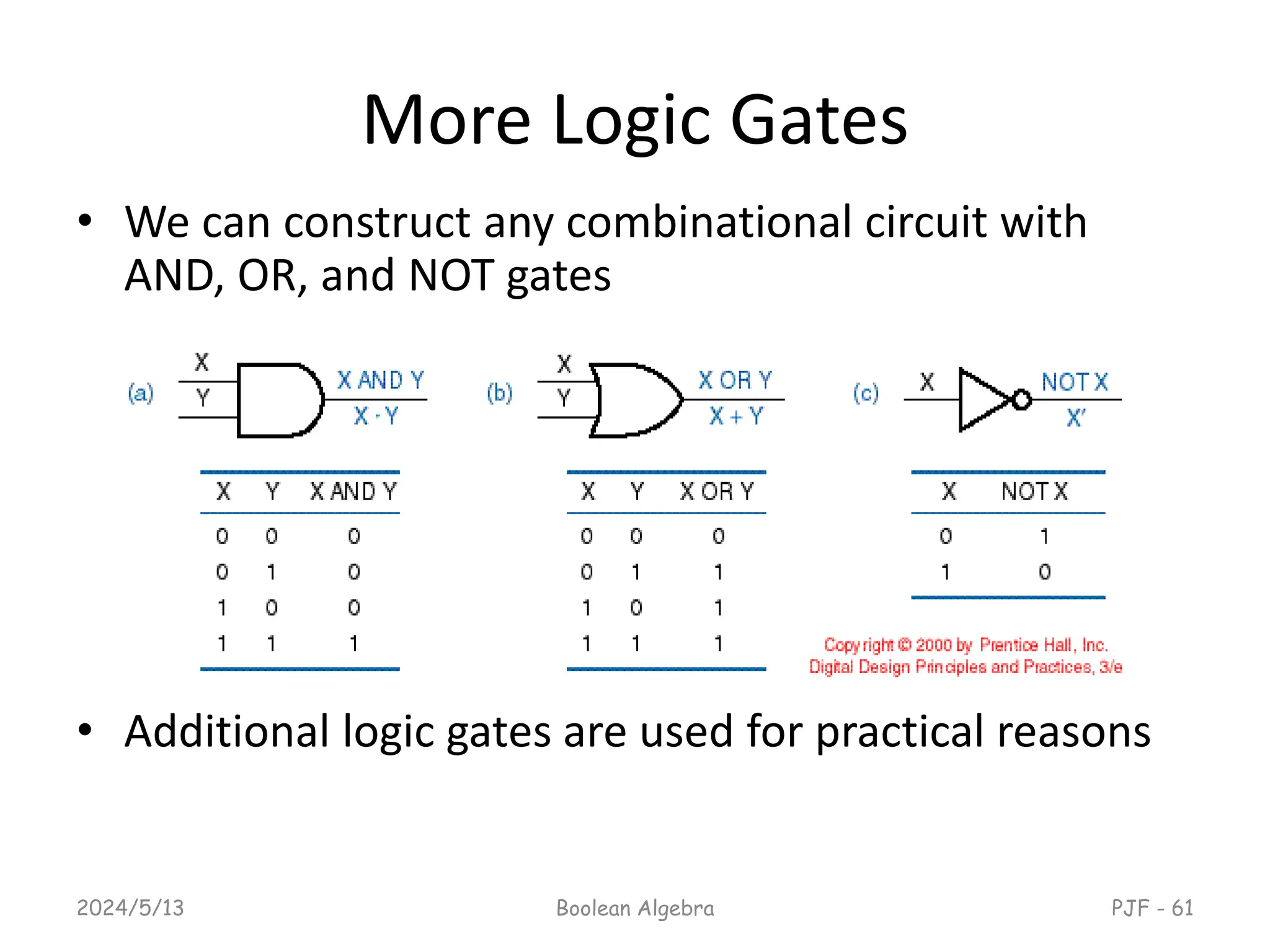
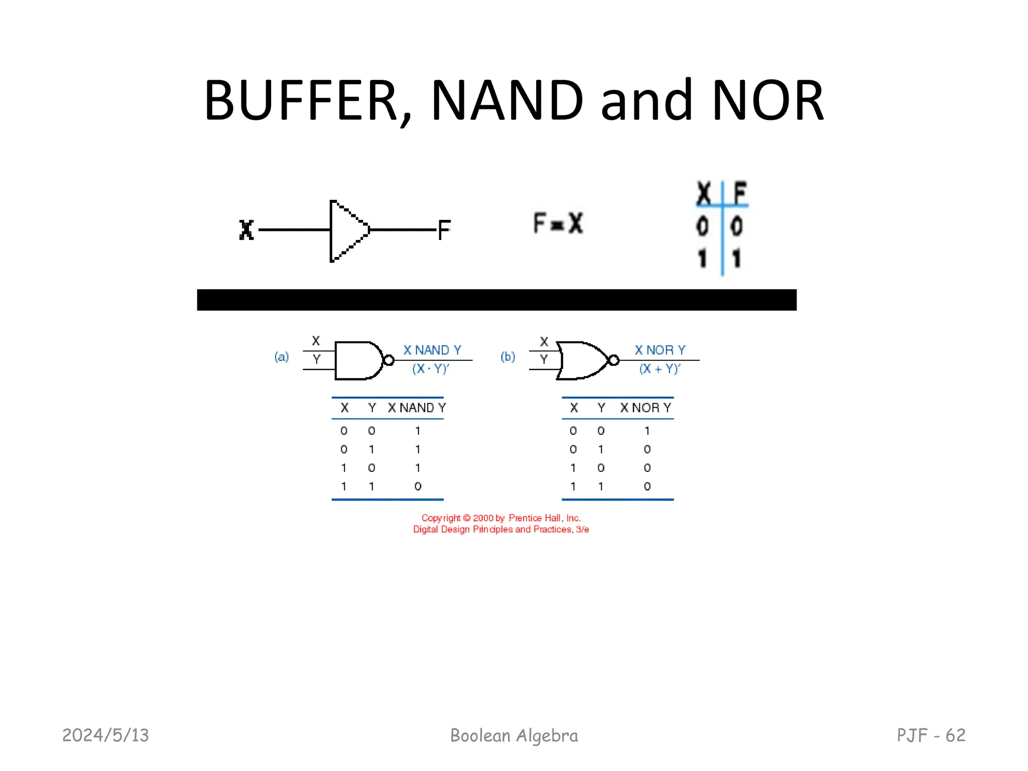
This document provides an overview of digital logic design focusing on binary logic, gates, and Boolean algebra. It explains fundamental concepts such as standard and canonical forms, simplification techniques using Karnaugh maps, and properties of Boolean algebra. Additionally, it covers truth tables, logic gates, and algebraic manipulation to optimize digital circuits.