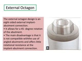
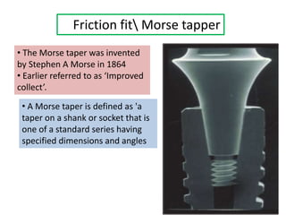
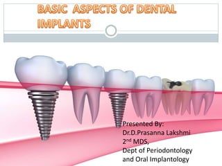
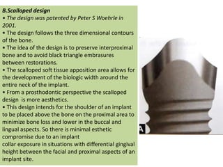
Presented By:
Dr.D.Prasanna Lakshmi
2nd MDS,
Dept of Periodontology
and Oral Implantology
Contents
 INTRODUCTION
 TERMINOLOGIES
 HISTORY
 CONCLUSION
 RATIONALE
 ADVANTAGES & DISADVANTAGES
 CLASSIFICATION
 PARTS OF DENTAL IMPLANT
 DENTAL IMPLANT DESIGN & SURFACE TOPOGRAPHY
INTRODUCTION
Dental implants  designed to
provide a foundation for
replacement of teeth that look,
feel, and function like natural
teeth.
TERMINOLOGY
Any object or material, such as an alloplastic
substance or other tissue, which partially or
completely inserted or grafted into body for
therapeutic, diagnostic, prosthetic or
experimental purposes.
Can be defined as a substance that is placed into
the jaw to support a crown or fixed or removable
denture.
Charles M Weiss
A prosthetic device or alloplastic material
implanted into oral tissues beneath the mucosal
or periosteal tissues and/or within the bone to
provide retention and support for fixed or
removal prosthesis. Edward J Fredrickson
IMPLANT
DENTAL
IMPLANT
DENTAL
IMPLANT
Archeological findings showed that the ancient Egyptian and South
American civilizations already experimented with re-implanting lost
teeth with hand-shaped ivory or wood substitutes.
In the 18th century lost teeth
were sometimes replaced with
extracted teeth of other
human donors.
HISTORY
2500 BC - Ancient Egyptians -
gold ligature.
500 BC - Etruscan population -
gold bands incorporating pontics.
500 BC - Phoenician population -
gold wire.
300 AD - Phoenician population -
Carved Ivory teeth.
600 AD - Mayan population -
implantation of pieces of shell.
1943 –Dahl- subperiosteal type of implant
Late 1970s and Early 1980s - Tatum - custom
blade implants of Titanium alloy
Early 1980s - Tatum – Titanium root form
implant
Modern Historical Developments
The first Subperiosteal Implant was placed in 1948 by Gustav Dahl
The Endosteal Blade Implant, introduced independently in 1967 by
Leonard Linkow and Ralph and Harold Roberts
After 1980s –hollow basket Core vent
implant Niznick et al
-Screw vent implant
-Screw vent implant with
Hydroxyapatite coating
- Implant with titanium plasma
spray
The quantum leap in Oral Implantology was
achieved in 1952 in Sweden by
PER INGVAR BRANEMARK
He founded the phenomenon of Osseointegration
Dr. Branemark's research shifted more towards the use of
titanium appliances in human bone, including the use of titanium
screws as bone anchors for lost teeth.
RATIONALE
Implant dentistry is a
boon for restoration of
missing teeth.
What makes implant dentistry
unique is the ability to achieve
replacement of teeth
regardless of atrophy,
disease, or injury to the
stomatognathic system
It overcomes many
disadvantages of
other conventional
methods of
restoration ie.,
removable and fixed
prosthesis.
Why are Implants preferred over Dentures
and Bridges ?
Stability
Grinding of adjacent healthy teeth
Chewing efficiency
Comfort /artificial feeling
Protection of the jawbone
Eating habits
ADVANTAGES OF IMPLANT-
SUPPORTED PROSTHESIS
Maintain bone height & width
Restore and maintain occlusal
vertical dimension
Maintain facial esthetics
Improve esthetics
Improve phonetics
Improve occlusion
Increase prosthesis success
Improve masticatory
performance/maintain muscles of
mastication and facial expression
DISADVANTAGES OF DENTAL IMPLANTS
Very expensive.
Cannot be used in medically compromised patients who cannot
undergo surgery.
Longer duration of treatment and tedious fabrication
procedures.
Requires a lot of patient co-operation because of repeated recall
visits for after care is essential
CLASSIFICATION
&
Types of Dental and
Craniofacial
Implants
Classification By Design
Epiosteal Intramucosal Transosteal Endosseous
Subperiosteal
SUBPERIOSTEAL IMPLANT
•These epiosteal implants are
placed beneath the periosteum
overlying the bony cortex.
•They are lightweight, custom
made metal frameworks that fit
over the remaining bone. A single
implant can support a full arch
restoration.
•These are indicated when the
bone has atrophied and the jaw
structure is limited.
• It can be used for both partially edentulous or completely
edentulous conditions .
• These implants are usually made of Vitallium alloys,
aluminium oxide, carbon or titanium. They are more
successful in the mandible than in maxilla.
INTRAMUCOSAL IMPLANTS
• Dahl in 1943 developed Intramucosal or
button implants also known as mucosal
inserts.
• These implants are mushroomshaped
inserts which are usually attached to the
intaglio surface of the denture and fit
into specially prepared indentations in
the roof of the mouth.
• The inserts provide excellent stability
and retention and are mostly used along
with removable partialdentures.
• These inserts damage the tissues and
are avoided in today's dentistry.
• They are also called as staple bone
implant, transmandibular
implant.They penetrate both the
cortical plates and pass through the
entire thickness of the alveolar bone.
• Their use is restricted to the anterior
area of the mandible.
• They have excellent stability because
the implant engages the cortical
plates on either side of the bone
• Diadvantages:
need for extraoral surgical
site in chin region
3. TRANSOSTEAL IMPLANT
Endosseous Implants
Intra oral Implants Extra Oral Implants
Special Conventional
Orthodontic
Zygoma
Pterygoid
Based on Implant Level
Based on Implant Size
Based on Platform Switch
Design
Intra oral Conventional Implants
Based on Implant
Level
Bone level
Implants
Tissue Level
Implants
Based on Implant
Size
Narrow Platform
Implants
Regular platform
implants
Wide platform
implants
Mini dental
Implants
Based on Platform switch
design
•Bone resorption upto 1st thread is considered as normal in implant survival.
• (GARDENER 2005) Found that there was no boneloss in patients where
abutment was narrower then implants
RATIONALE: The design moves the implant abutment junction towards
the centre of implants and away from the tissues.
•This moves the zone of bacterial colonozation inwards and provides a
mucosal seal
•Biomechanically, the forcesare directd more towards the centre
protecting the crest from stress.
•It has been proven thatShear force acting on a platform switched
implant is lower than a conventional “platform-matched”implant.
Platform-Switched
implants
•These implants (inbuilt platform
switching) are designed such that
the crest has a reverse bevel that
acts as a platform
switch.
•Any abutment placed on these
implants will
have the gap/undercut for gingival
collar formation.
•Most implant companies have
adopted this design over the past
decade.
Non-paltform
switched implants
•These implants have a flat crestal surface.
There is no bevel.
•These implants have a seamless implant
abutment junction.
Platform switched
implants
Universal switching implants
•These are essentially
non platform
switching implants.
• The abutments are
available in different
configurations that
can make them
appear platform-
switched if required
Orthodontic implant
•These are very small screws that are used
as orthodontic anchorage.
• Once osseointegrated, the bone around
the implant does not remodel.
•Hence implant remain stationary and
provides excellent anchorage.
•These implants resemble surgical screws
with a slot and hole in the screw head.
•The slot and channel are provided to tie
in arch wires.
Intra oral special implant
Zygoma Implants •Zygomatic implants were described by
Branemark in 1998 as a suitable
alternative for fixed restorations in the
atrophic maxilla
These are long screw-
shaped implants
were developed as an
alternative to bone
grafting and sinus
augmentation.
These implants are not universally used because of the
following limitations:
• The implants are very large over 30-50 mm long.
• They are very technique sensitive to place. In many
centers only an oral surgeon is considered qualified to
place these implants.
• The amount of bone loss in failed cases is very high.
• The initial designs had the implant emerging in the
middle of the palate making it unaesthetic and very
difficult to restore. It required an RPD like framework.
• Since only the apical portion of the implant engages the
bone, the implant has a very low crown implant ratio.
• These implants are 7-8 times more expensive than
conventional implants.40 With such high costs and low
predictability these implants end up as the last choice
for most doctors.
Palatal screw
access for the
zygoma
implant
Unaesthetic platal screw
access for zygoma
implant can significantly
hamper the quality of
treatment
Pterygoid implants
•These implants are placed
through the maxillary
tuberosity into the
pterygoid plate.
•They are angulated
impalnts like zygoma but
much shortened(18mm).
•They are designed to
penetrate into the
pterygoid plates of the
sphenoid bone.
•They are inserted at a
70degree angle posterior to
the maxillary ridge crest
Extral Oral Implants
Occular implants
•Rehabillitation of
Ophthalamic socket
•Occular implants
provide a substarte
base for reconstruction
of eye
•The implant enhance
rapid vascularization
and softtissue growth
•Available as spheres; the
sphere diameter ranging
from 14mm to 22mm.
•Materials: Polyethylene,
bioceramics, hydroxyapatite
Cranial Implants
Cranial implants provide secure attachment of the prosthesis and obviates
the need for adhesives, double sided tapes, glasses (eye and ear prosthesis)
•Availability of bone in the temporal, orbital, and midfacial region is not
sufficient for the placement of standard-sized endosseous implant
•To compensate for this limitation they are shorter(3-4mm length) and have
perforated flange (5-6mm) that facilitates initial stabilization of implant.
Classification by Material used
1. Pure Titanium Implants
2. Titanium Alloys
3. Titanium Coated with Tantalum Implants
4. Hafnium and Osmium Implants
5. Titanium-Zirconium Implants
6. Zirconia Implants
7. Sapphire Implants
8. Stainless Steel Implants
9. Cobalt Chromium Molybdenum Implants
10.Vitreous Carbon Implants
11.Tubingen Aluminum Ceramic Implant
12.Bioimplants
Pure Titanium Implants
• Discovered – WILHELM GREGOR 1789
• Gained popularity in Dentistry when WILHELM KROLL developed
deoxidation process to purify titanium tetrachloride
• Available in Solid cast bars
• Exists in two phases at the microscopic level
Hexagonal crystal lattice phase(alpha form)
in room temp
Body centred cubic form (beta form)
at 883⁰
Bcc titanium is more dense
• Pure titanium available in 4forms based on O2, Fe, N2
Grade 1- More Purest not used because of Brittle
nature. Only BRANEMARK system continues touse it because they
usespecial hardening process to improve strength of metal.
Grade 4- stronger and has maximum o2 gradiant
Pure titanium rods
Titanium Alloys
• To overcome the brittle weak nature of titanium many
manufacturers began making implants in titanium alloys.
• The most common titanium alloys used in dentistry is Ti6Al4V
•Titanium: exists in alpha phase (Hexagonal closed packed crystal
structure) in room temperature and in beta phase (Denser body
centred cubic crystal lattice) at higher temperatures.
β phase – more strength to stabilize β phase manufactures
add vanadium,molybdenum to stabilize beta phase at room
temperature
Titanium – under physiological conditions, in the presence of
air, water or any other electrolytes a spontaneous formation of ana
oxide occurs and get maintained on the surface of the metal
without apparent breakdown or corrosion.
Titanium Coated with Tantalum Implants
• Discovered by Swedish chemist, Anders Gustav Ekebereg in 1980
• It is a rare,High Corrosion-resistant transition metal .
• The metal forms two metals are
Tantalum Pentoxide
Tantalum tetroxide – more stable
• Zimmer is the 1st company to use Tantalum in conjunction with Titanium in
dental and orthopedic implants.
• Their PTTM (porous tantalum trabecular metal) implants is designed to
cover the middle portion of the implant.
• Trabecular pattern is shaped based on a repeating decahedron carbon core.
PTTM is composed of 2% carbon core and 98% tantalum. The middle portion
is laser welded to the apical and coronal portion of the implant.
•Apex fractured while placement into D1 bone.59 The company promotes
the use of this implants for more compromised cases (diabetes,
smoking, post-radiation, etc.).
Advantages
• Ta is said to enhance osteoblastic
differentiation potential (probably
because of HF etching).
• Increase in bone to implant interface
area—PTTM
• Simulates spongy bone is structure,
elastic modulus, stress distribution.
Disadvantages:
• Difficult to predict behavior if implant in complex oral
environment.
• Surface biofilm.
• Compromised immune ability at implant tissue surface
• Implant components prone to fracture ata the laser welded
junctions.
Hafnium and Osmium implants
•The Ti—Hf alloy system forms an α-
β isomorphous system.
•This alloys does not form any
intermetallic compounds (like the
different phases we see in
amalgam) and so there is no weak
phase.
•This provides excellent corrosion
resistance. The grain boundaries of
this alloys forms a characteristic
nanotubular structure on the
surface. This surface tomography is
said to improve osseointegration.
Titanium-Zirconium Implants
•Zirconium is the metal where as Zirconia is the Metal oxide.
•Zirconium is a biocompatible replacement to Aluminum and Vanadium used
in most titanium alloys.
•Sometimes Zirconium is only used as a surface coating on Ti6Al4V
• This alloyallows for SLA (sandblasted, large grit, acid etched) surface
treatment and is actively used by Straumann for their ROXOLID implants.
• Homogenous alloys can be used in narrower implants with out compromising
strength.
• These implants are avoided when heigher bending forces are expected eg:
canine restoration
Zirconia Implants
• Zirconia is a white
metallic oxide of
zirconium.
• It is extensivelyin high
strength ceramics.
•2nd most material used in
dentistry.
• Exceptional aesthetics
and lower plaque
accumulation.
• Implant is crystalline
white in color and does
not cause a grey hue
underthe gingiva
Sapphire implants
•Before Zirconia became popular,
many companies released implants
made of Alumina.
• These implants were crystallized
by edge-defined free fled growth
method.
•The crystalline structure is called
Sapphire.
• The material was very hard and
difficult to prepare the coronal
portion for abutment preparation.
• Some companies released a
combination of amorphous alumina
in the coronal size and crystalline
sapphire implant on the apical side.
Stainless steel implants
• Stainless steel in more versatile
metal used as implants formore than
a century.
• Older endosseous implats blade and
transosteal implants were made
exclusively in stainless steel.
•Vanadium surgical steel was not very
biocompatible and got replaced by
more biocompatible 18-8 stainless
steel that contained 8% Nickel and
18%Chromium.
• 316L grade is used as implant grade
stainless steel for orthopedic and
orthodontic implant.
•316L – 19% chromium, 14% nickel
and traces of molybdenum and has
high corrosion resistance
Cobalt chromium Molybdenum Implants
• This alloy was primarly
used to fabricate custom
designed frameworks.
• They had excellent
corrosion resistance and
did not require heat
treatment.
• Therefore, they could be
cast, annealed and directly
placed over bone.
Tubingen Aluminum Ceramic Implants
•This implant was invented by Professor
Willi Schulte from the University of
Tubingen, Germany.
•This implant is shaped like an irregular
conical cylinder with surface lacunae that
claim to allow osteoblastic growth.
• This implant is said to be made of
aluminium oxide.
• These implants are only used for partial
short span edentulous spaces.
• This material has good aesthetics and
tissue healing.
• This implant has lesser bone to implant
contact with increased rate of fracture
after 10years
Bioimplants
• This Austrian implant is marketed as the world’s
first immediate anatomic dental implant.
•The implant is made of zirconia and appears to
resemble a tooth
• The manufacturaing process is unique in that
each implant is custom made of a patient.
• The dentist is required to take a CBCT and send
to the implant company.
•They make a rapid prototype model of the tooth
to be extracted and modify the crown portion of
the model.
• The prepared model is then laser scanned and
the implant is milled from a medical grade
Zirconia block.
• Later the surface is sandblasted after that
impalnt is cleaned in an ultrasonic bath cointaing
96% ethanol for 10 mins, packaged and steam
sterilized. Within 10hrs the customized root
analogue implant is ready to use
Contraindications:
• Cannot be applied if the
tooth has already been
extracted weeks ago
• Grades I,II,III mobility
• Severe periodontitis
Classification of Implants
BASED ON BIOCOMPATIBILITY
•Alternatively, implants can also be classified based on
they way they encourage or tolerate bone growth
The most popular terms used in this regard are:
1. Osteoconduction (guiding the reparative growth of the
natural bone)
2. Osteoinduction (encouraging undifferentiated cells to
become active osteoblasts)
3. Osteogenic (Living bone cells in the graft material
contribute to bone remodeling)
4. Osseoneutral (they donot create any adverse response
from the bone tissue).
Osteoinduction: Here, the material stimulates primitive, undifferentiated
and pluripotent cells to develop into the bone-forming cell lineage.
•Many manufacturers add osteoinductive bone markers and cell
mediators to induce osteoinduction . The most common biomimicking
factors experimented for osteoinduction in dental
implants include.
• Insulin - like growth factor (IGF I)
• Insulin-like growth factor (IGF II)
• Fibroblast growth factor ( FGF)
• Transforming growth factor (TGF-P )
• Platelet -derived growth factor (PDGF)
• Bone morphogenetic protein (BMP)
• Fibroblast growth factor (FGF)
• BMP-2
• BMP-7
• Calcium phosphate coating
• Antibiotic-coated HA coating.
Osteoconduction: Osteoconductive surface is one that
permits bone growth on its surface or down into pores,
channels or pipes.
•Bone growth on an implant surface depends on the action of
differentiated bone cells.
•These cells may originate either in pre-existing preosteoblasts/
osteoblasts that are activated by trauma or in cells recruited
from primitive mesenchymal cells by osteoinduction.
• There is a debate concerning whether or not a particular
biomaterial acts as an osteoinductor, since the injury at
placement is sufficient to recruit previously undifferentiated
bone cells.
Osteogenic: Osteogenic coatings on implant
surfaces enhances osseointegration.
•They differ from osseo induction in that the
implants is coated with living
osseoprogenitor cells.
•These implants are yet to become
mainstream due to ethical and biological
concerns. Nevertheless these surfaces have
the best bone forming ability and are
expected to become very popular in
the near future.
Implant design has become synonymous with ENDOSSEOUS
implant design
Implant MACROGEOMETRY Implant MICROGEOMETRY
Crestal module
Implant-abutment connection
Body of implant
Apex of Implant
Additive characterization
Substarctive
characterization
Combination of both
•It is the portion of the implant that engages the crest
of the bone and is designed to accept the prosthetic
component.
•This component functions to transfer the
majority of the occlusal load to be placed the surrounding
bone.
• The crestal module is designed to be placed flush within
the bone
Bone level implant
Tissue level implants
•The occlusal surface of the crestal module has a platform
on which the abutment sits and transfers its occlusal load.
IMPLANT
MACROGEOMETRY
Crestal module
The implant abutment connection in a crestal module may have the
following features:
• Antirotational .component in the shape of a star or hexagon that can hold
the abutment and prevent it from rotating.
• This connection may either be within the implant body (internal
connection/internal hex) or out side the implant
body ( external connection /external hex).
• Many companies design the crestal module with a smooth surface to
reduce plaque accumulation.
• Some companies have microthreads to encourage gingival attachments.
The clinical benefit of this feature is yet to be substantiated.
• The length of the crestal module (0.5 to 5mm) varies acc to various implant
companies
The crestal module can be described based on the following
features:
• Collar design
• Shape
• Surface
• Presence of microthreads
• Type of implant abutment connection
Collar design
The implant collar is not ideally designed
for load-bearing.
Based on collar design, the implants can
be classified into:
1) Straight or Parallel- sided : This is the
most common collar design.
2) Divergent or Flared collar: It produces
the least amount of stress on the crestal
bone, and is more biologically compatible.
This is probably due to the increased
surface area. A divergent collar gives a
relatively better soft-tissue profile.
3) Convergent or Tapered: This design has
a more favorable stress distribution.
1)Straight or
parallel sides
2)Divergent or
flared collar
3)Convergent or
Tapered
Collar shape
A. Straight design
•The straight or flat crestal module design is
the most commonly manufactured implant
crestal module design.
•These crestal modules could be either
polished or surface-treated.
•They may also have microthreads to improve
soft-tissue integration.
•The stress distribution pattern in this design is
static, (meaning this does not increase or
decrease the force distribution in
the crestal area).
•Misch and Bidez in 1999 noticed that parallel
crestal module design produced a lot of shear
stress in the crestal region, thereby causing
bone loss. They observed that angulating the
crestal module by 20° decreased the amount
of bone loss.
B.Scalloped design
• The design was patented by Peter S Woehrle in
2001.
• The design follows the three dimensional contours
of the bone.
• The idea of the design is to preserve interproximal
bone and to avoid black triangle embrasures
between restorations.
• The scalloped soft tissue apposition area allows for
the development of the biologic width around the
entire neck of the implant.
• From a prosthodontic perspective the scalloped
design is more aesthetics.
• This design intends for the shoulder of an implant
to be placed above the bone on the proximal area to
minimize bone loss and lower in the buccal and
lingual aspects. So there is minimal esthetic
compromise due to an implant
collar exposure in situations with differential gingival
height between the facial and proximal aspects of an
implant site.
Collar size
Generally, the crestal module is designed to have a
slightly larger diameter than the body of the implant.
This has the following advantages:
 Improves the initial strength of implants
 Prevents the entery of bacteria and fibrous
tissue by sealing the osteotomy site
 Decreases the strees concentration
Collar surface
The crestal module may either have a smooth or a rough
surface.
•SMOOTH SURFACEThe earlier concept was to always have a
smooth collar so that cleaning and maintenance were easy.
•smooth collars produced greater shear force due to low
surface area. This led to frequent marginal bone loss.
Since majority of the implants are bone level implants,
the need for a smooth, easy to maintain surface has become
unnecessary.
•ROUGH SURFACE crestal modules have become more
common. Also, the initial sulcus depth of an
implant is 3 mm, whereas the bristles of the brush can reach
only up to 0.5 to 1 mm, making the crestal module
inaccessible to clean.
Surface roughness is created by the same process used
to treat the implant body.
Some companies have additional features such as
microthreads to improve osseointegration at the crest level.
NON POLISHED
COLLAR
POLISHED COLLAR
Microthreads
• These are small grooves placed on the crestal module to improve
the surface area of the bone implant interface near the crest.
• Microthreads were first introduced to preserve marginal bone and
soft tissue surrounding the implant.
•They help in maintaining the crestal bone height by dissipating
occlusal loads (mainly vertical).
• Microthreads can be of the following designs:
- Horizontal
- Parabolic or scalloped
IMPLANT ABUTMENT CONNECTION
•The implant abutment connection is the junction between the dental implant
and its abutment.
•It is one of the critical determinants of the strength and stability of an implant-
supported restoration and has a major role to play in the success of the implant.
There are two types of implant-abutment connections:
• External connection : In case of an external connection, the crestal module of
the implant has a male component which fits in the female component present
in the abutment.
• Internal connection : Here the connector projects from the surface of the
abutment and it fits into a depression on the surface of the implant.
External Internal
THIS IS ANTI ROTATIONAL FEATURE OF IMPLANT SYSTEM
A) External
connection
B) Internal
connection
External abutment connection
Initially all implants had this type of
connection.
• The connection projects 0.7 mm outside
the crestal module.
• The external connection also serves as a
torque transferring attachment for the
fixture mount during the initial placement
of the implant. (It behaves like a bolt head
and the abutment fits like a spanner.
• All rotational forces on the crown are
transferred to the implant.
DISADVANTAGES
 Increased incidence ofscrew loosening
 Collar fracture
 Micromotion at the implant abutment
interface
There are many types of external connections are
described:
 Tapered hexagon
 External Octagon
 Spline dental implant system
Tapered hexagon
• The tapered hexagon connection has six
sides with 1.5-degree taper.
• It also has a corresponding close
tolerance hexagonal abutment recess that
can be friction-fit onto the hex.
• This system is also known as the Hex
Lock Innovation.
• Features:
Increased abutment stability and
accurate transfer procedure.
Claims to have zero micromotion at the
implant abutment junction.
[Examples, Spectra implant systems,
Swede-Vent TL (Paragon Implant Co.,
Encino,CA)].
External Octagon
The external octagon design is an
eight-sided external implant-
abutment connection.
• It allows for a 45- degree rotation
of the abutment.
• The main disadvantage is that it
is not compatible withthe use of
angled abutments and offers little
rotational resistance at the
implant-abutment connection.
Spline dental implant system
The spline dental implant system was developed by Calcitek ( Calcitek, Carlsbad,
CA) in the year 1992.
•The system has six teeth projecting outward (referred to as Spline) from the
crestal module of the implant that corresponds to the six grooves presented in
the abutment.
• A snugly fitting implant abutment junction with excellent positional accuracy is
achieved. Since the splines are not continuous, there may be some risk of
fracture of individual spline teeth.
Internal abutment connection
• The first implants with internal connections were designed in 1986 by Dr
Gerald A Niznick
• The system had a 1.7 mm-deep hexagonal connection with a 0.5 mm-
wide 45° bevel.
• Features:
- All occlusal forces are directed towards the center of the implant
and so it distributes the forces evenly.
- The internal wall engagement of the connector is deep and the
abutment screw is well shielded within the implant preventing screw
failure. (In other words, the retention is provided by the internal walls of
the connection and retaining screw is passive and will not fracture often).
- Provides a good microbial seal, thereby preventing infections.
- An internal connection is preferred in esthetic restorations as
there is sufficient height available to place the abutment.
• It is also useful in cases with reduced interarch space.
Types of internal abutment connections:
1. Passive fit /Slip fit joint (space exists between mating components).
- 6-point internal hex
- 12-point internal hex
- 3-point Internal Tripod
-Internal octagon
2. Friction fit (no space between mating components)
Locking taper/Morse taper:
- 8-degree taper
- 11 -degree taper
- 1.5 -degree tapered rounded channel
PASSIVE FIT
Six point internal hex
• Majority of the current implant systems come with an internal hex abutment
connection.
• The hexagon is recessed into the body of the implant and the abutment can fit
at every 60- degree rotation of the implant. This makes it versatile and useful in
poorly angulated connections.
• The intraoral forces are distributed evenly within the implant.
• The implant-abutment joint stability is greater in a sixpoint internal hex system.
Twelve point internal hex
• The twelve-point internal hex provides an opportunity to place
the abutment on the implant for every 30- degree rotation.
• It is useful while choosing angulated abutments as it offers
more freedom of positioning the abutment.
• This system distributes stresses evenly at the implant abutment
interface.
Three- point internal tripod
• The internal tripod implant has a triangular internal geometry
and it allows positioning of the abutment at a 120-degree rotation.
• The disadvantage is that there is limited range of freedom for
positioning of the abutment over the implant.
Internal octagon implant
•This system has an 8-sided internal octagonal geometry, thereby
allowing angulation of the abutment at every 45- degree positioning
of the implant over the abutment at every 45-degree rotation.
• The internal octagonal implant-abutment connection offers
minimal rotational and lateral resistance during function.
Friction fit Morse tapper
• The Morse taper was invented
by Stephen A Morse in 1864
• Earlier referred to as ‘Improved
collect’.
• A Morse taper is defined as 'a
taper on a shank or socket that is
one of a standard series having
specified dimensions and angles
Cold Welding in Morse taper
• It can be described as a 'Cone-in-Cone Mechanism' that tightens with
increased friction during usage. It is better than a latch - type connection that
can become loose with wear. Here even if the cone wears out, it will fit in
tighter by virtue of its design.
• A Morse taper consists of two important components,
namely the
Trunnion (male portion) and
Bore (female portion).
• When the trunnion is tapped into the bore contact it compresses against the
walls of the bore and, as a result, the bore expands.
• This results in cointegration (locking), along with material transfer that
occurs across the zone of contact (cold- welding).“
•Cold or Contact Welding is a solid state welding process in which joining takes
place without fusion at the interface of the two parts to be welded“.
•Cold Welding may also be defined as 'an increase in loosening torque with
respect to tightening torque and may result in the lack of retrievability'.
• The degree of fit is determined by the dimensions of the two components
(male and female regions).
• Morse taper reduces the microbial leakage by providing an airtight seal and
also reduces the incidence of screw - loosening .
1.5⁰ Morse taper
8⁰ Morse taper
11.5⁰ Morse taper
Platform switching
The Platform switching concept is based on the use of an
abutment smaller than the implant neck.
• It was introduced by Richard J Lazzara in 2006 to prevent crestal
bone loss.
• The abutment diameter is smaller than the implant crestal
module. This moves the implant abutment junction (IAJ) away
from the outer margin of the implant.
• Moving the IAJ inward moves the bacteria more internally and
therefore away from the bone crest thereby
reducing the crestal bone loss.
• Also, a mucosal seal is formed when the abutment base is
smaller than the implant platform.
• The design also helps reduce stress on the surface of the
crestal module.
• The shear force exerted on the cortical bone in the platform
switching model is lower than in the conventional mode.
• Since bone response is different for platform-switched
implant even before loading it should be remembered that it
is more of a biological factor than a mechanical factor.
Body of Implant
•The body of the dental implant is the part between the
crestal module and the apex of the dental implant.
•The structure of the body of the dental implant is
described based on its taper, thread design and other
special features.
Taper
Macrogeometery of the implant body
Taper
The taper of the implant refers to the parallelism between the walls of
the implant.
Based on taper of the implant, there are three forms:
1) Cylindrical form:
Implant diameter is constant from crest to apex
2)Root form implant:
crest to middlethird – constant diameter
middlethird to apex it tappers
3)Bioimplant:
Custom milled acc to the shape of extraction socket
1) 2)
3)
Macrogeometry of the implant body
Based on thread design implants can be:
A) Threaded implants
B) Nonthreaded implants
Threaded implants
Threaded implants are avilable in various designs
On the basis of following parameters:
Thread Shape
Thread Pitch
Thread Depth
Thread Width
Face angle, thread angle
and flank angle
Thread Lead
Thread Start count
Thread Diameter
Thread shape
• Based on the cross-section of the thread,
thread shape can be of five types.
- Square-shaped
- V- shaped
- Buttress or Breech lock design
- Reverse Buttress
- Spiral
- Thread in thread/groove in groove
The purpose of the thread on the implant surface
primarily aids in mechanical retention as a result of
increased surface area for osseointegration.
SQUARE THREADS V-SHAPE THREADS BUTTRESS
REVERSE BUTTRESS SPIRAL THREADS THREAD IN THREAD/GROOVE
IN GROOVE
Thread pitch
•Thread pitch refers to the
distance from the center of
the thread to the center of
the next thread
• Measured parallel to the
axis of a screw
• Fine pitch increase
threads – increase surface
areaunit length
• Fewer threads --- easy to
bone tap
• The thread depth is defined as the
distance from the tip of the thread to the
body of the implant.
• Outer diameter is the width of the
implant measured from the maximum
width of the thread.
• The inner diameter of an implant is the
width of the implant in between the
threads.
Thread depth
Thread width
•The thread ROOT -- the base of
the thread whereas the thread
CREST-- is the apex (outermost
point) of the thread.
• Thread width is the width of the
thread measured at the thread
crest.
•Implant with higher thread width
will face more resistance during
insertion.
Face angle, helix angle, and flank angle
FACE ANGLE: angle fromed between the
face of the thread and plane perpendicular
to long axis of implant
Coronal face angle is the face angle
formed on the surface of the thread towards
the crown.
Apical face angle is the face angle formed
on the surface of the thread towards the
apex of the implant.
HELIX ANGLE: angle formed
between the thread helix and the
line perpendicular to long axis of
implant
FLANK ANGLE or
THREAD ANGLE is
the angle between the
coronal and apical facial
surfaces
of two adjacent threads.
• Square thread has a
zero- degree flank angle
• V-shaped thread has an
obtuse flank angle
• In a buttress thread the
flank angle is equal to the
face angle.
Thread lead
It is the property of the thread design that determines
the apical movement of the implant for one complete
rotation (360°).
It is determined by the thread helix angle. Implants
with a higher thread helix angle will move faster into
the bone for each 360° turn
Apex of the Implant
The dental implant apex is the portion of
the implant that replaces the anatomic
apex of the tooth.
• There are two types of implant apices
Self Cutting apex
Non cutting apex
Self cutting apex
•Selfcutting implant apices have
threads on the apex that are
designed to engage and cut through
the bone.
•Currently, these are more preferred
as they engage well into the bone,
thereby increasing the stability of
the implant,and the surface area for
osseointegration
Non cutting apex
•Noncutting apices are seen mostly in
cylindrical implants with a nonthreaded
body design.
•Many threaded implants come with a
noncutting apex as well.
•These implants have a vent in the apex
which helps in engaging the implant to the
bone and also act as an anti-rotation
feature.
•Currently implants with noncutting
apices are not used due an increased
incidence for failure.
Anti-Rotation Features
Dental implant apices have been
transforming over the last
few decades and most of the newer implants
are incorporated with antirotational features.
These anti-rotational features include:
• Screw vents
• Slots
• Grooves
• Aggressive apex : placement of grooves in a
cutting apex
Eventually when these implants are placed,
bone growth is seen in these grooves, vents
and slots in the apical region, thus preventing
the implant from rotation.
Miscellaneous apex designs
There are certain modifications made
in the apex of dental implants to
improve retention and stability
features:
• Apical dimples
• Grooves with dimples
• Grooves continuous with the body
• Holes at the end of body grooves
• Alternate holes and grooves
• Split flared apex
Implant microgeometry
•Microgeometry deals with surface characteristics of an implant.
•Implants can be classified based on there surface into 3 major
categories
1)ADDITIVE SURFACE CHARACTERIZATION:
HA coating
TCP coating( Tri Calcium Phosphate)
Zirconia coating
Titanium sintering
Titanium plasma spray
Anodization
Sintered implants
2)SUBTRACTIVE CHARACTERIZATION:
Acid etching
Alkaline etching
Sand blasting
Sand blasting + Acid etching
Grit blasting
Titanium blasting
Laser lithography
3)Combined additive and subtractive characterization:
Acid etching + collagen coating
Acid etching + anodization
Acid etching + biomimetic coating.
ADDITIVE SURFACE
CHARACTERIZATION
•Here, the implant surfaces are roughened by adding
materials onto them.
•The material may either be added by simple
precipitation or atomizations or electrochemical
deposition or super-hot plasma spray or by sintering
HA coating
•HA coating on implants was
introduced by Dr De Groot in
1994
•They have excellent
osseointegration and so were
very popular in the early 90s.
•The coatings were sprayed onto
the surface at high temperatures.
•Some designs were more prone
to microbial colonization
in exposed area.
TCP Coating
•Similar to HA coating but
difference is coating is not
continuous, it is dispersed.
• TCP(Tri Calcium Phosphate)
particles help in
osseointegration in the initial
stages of healing.
• This surface is said to
improve bone bonding and
retain more bone fragments
when removed
Zirconia coating
• Zirconia ceramic is coated and fired in a furnace on a titanium core.
• The coating consits of Zirconium dioxide(43%)
Titanium dioxide (49%)
Phosphorus pentoxide(8%)
Microcrystalline zirconium titanate (bioactive glass)
• Bioactive glass is known to improve proliferation and expression of
osteocalcin and bone sialoprotein
Titanium Sintering
• Endopore implant is a Canadian
implant fabricated by sintering
small millimeter size beads on the
surface of titanium core.
• The implant promotes bone
growth into the space between
the beads.
• Disadvantage: bacterial
accumulation under the beads of
the rough surface and once the
bacteria enter the coating, they
can freely colonize all the way
upto the apex of implant
HA Plasma Spray
• Plasma spraying is a process that involves the heating of hydroxyapatite
(HA) crystals to the temparature of 15000-20000k at this temp material
transform to plasma.
• Coating a plasma state material provides excellent bond strength.
• Benfits: 1) it makes inert material fuse together
2) it does not damage the substrate surface.
• To avoid plasma spray react with material it is done in presence of Argon
gas
• Material is coated with thickness of about 50-100 microns it enhances
osteogenesis
Anodization
• Anodization is an electrochemical process that increases surface roughness
and the thickness of the Ti oxide layer, and this layer increases the wettability
and biocompatibility of surfaces and ultimately improves osteoblast
attachment, proliferation, and bone response.
•The main aim of this process is to increase the thickness of the oxide layer to
more than 1000 microns.
•Dental implants, anodization is carried out by applying 100 V on the titanium
implant immerse in electrolytes like, H3P04, and Trisodium Phosphate.
•This results in a surface with microridges of variable diameters which facilitates
increased cell attachment and proliferation.
• Today most implants use some form of anodization process along with acid
etching.
Sintered Implants
•Direct metal laser sintering (DMLS) is the latest and greatest technology be
deployed in Dentistry.
•This technology permits fabrication of complex 3D objects from powder based
materials based on a computer-designed model.
•DMLS technology allows the fabrication of titanium dental implants with an
inherent porous surface.
•In this technique, the titanium implant is built layer by layer using powdered
Ti6Al4V, a radiant heater and a computer controlled laser. The machine adds a
layer of powder and sinters them with a laser.
•Adva: matches Yield streangth and elastic modulus of bone
SUBTRACTIVE
CHARACTERIZATION
•Added (coated) materials are always prone to
delamination.
•Therefore most manufacturers moved to
subtractive characterization.
• They produce microrough indentations on the
implant, which can enhance bone response
Acid Etching
•In this technique, the metallic implants are immersed in
an acidic solution which erodes its surface creating micro
pits with sizes ranging from 0.5 to 2 pm in diameter.
• Immersion of titanium implants for several minutes in a
mixture of concentrated HCI and H2S04 heated above
100°C (dual acid etching) is also used by some
manufacturers to produce a controlled microrough
surface.
The factors that affect the quality of the surface roughness
are:
• Concentration of the acid
• Duration of etching
• Temperature of the acid.
Alkaline Etching
•Similar to acid etching titanium can also be etched with
alkaline solutions. Caustic soda (Sodium hydroxide—NaOH) is
the most common alkali that is used.
•When titanium is etched in 4-5 M NaOH (1 M NaOH has
58.44 g/1 L) 600°C for 24 hours,it produces sodium titanate
gel with an irregular topography and a high degree of open
porosity.
•However, etching titanium in a boiling alkali solution (0.2M
NaOH at 1400degree C for 5h) produces a rough surface with
high density nanoscale pits
Sabdblasting
•Blasting an implant surface with alumina particles of
varying sizes is one of the most commonly used surface
characterisation techniques.
•The particle sizes may vary from small to large grit ( 150-
350 microns).
•These particles are bombarded onto the surface of the
implant and the resulting roughness increases the surface
area.
•This is said to facilitate adhesion, proliferation and
differentiation of osteoblasts.
•The remaining Al203 particles may inhibit osseointegration
Sandblasting + acid etching
•SLA (Sandblasted-Large Grit-Acid-etched).
•This technique was first introduced by Buser etal 1991.
•The SLA surface is produced by a large grit sandblasting process
with corundum particles that leads to a macroroughness on the
titanium surface.
•This is followed by a strong acid-etching bath with a mixture of
HCI/H2S04 at elevated temperature for several minutes.
• This produces the fine 2-4 pm micropits superimposed on the
rough-blasted surface.
•The surface is not microporous and is, therefore, less likely
to harbor bacteria. These implants show superior bone to
implant contact and decreased healing time.
Grit Blasted
•Grit blasting is similar to sandblasting and is used specifically
to denote procedures that use larger size particles.
•Hence the surface has large size irregularities
Titanium blasting
•Stig Hansson in 1989 invented surface characterization by
blasting Titanium dioxide particles on the surface of the
implant.
•Commercially, Astratech made Tioblast implants that
were blasted with 25 pm titanium dioxide particles.
•This surface topography is characterized by 1-1.2 pm pits
•In 2004, Astratech improvised their Tioblast surface by
etching with hydrofluoric acid.
•This became the critically acclaimed osseospeed surface.
Laser Lithography
•It is also known as Laser Peening. Laser lithography
involves the use of high intensity (5- 15 GW/cm2)
nanosecond pulses of (10-30 ns) laser beam striking a
protective layer of paint on the metallic surface.
•These implants demonstrate a regular honeycomb pattern
with small pores.
•This techpique also introduces compressive stresses in the
implant structure which improves strength
Implant
components
PARTS OF DENTAL IMPLANT
Crown: Material Used:
Porcelains (metal supported
or metal free) or metal
(normally gold)
Abutment: Materials Used:
Titanium.
Implant Body or Fixture:
Materials Used: Titanium &
titanium oxide
Implant Fixture
• The term fixture is used
synonymously for the implant itself
which is inserted and gets
osseointegrated with the bone.
• It works as the tooth root, and
various kinds of components are
used to cover it, make its
impression, and retain or fix the
prosthesis on top of it.
CREST MODULE
• The crest module of an implant body is that portion designed to
retain the prosthetic component in a two-piece implant system.
• It also represents the transition zone from the implant body
design to the transosteal region of the implant at the crest of the
ridge.
Implant Apex
• The implant apex portion is often
tapered to permit ease of initial
placement into the osteotomy.
• An antirotational feature of an
implant may also be included,
which has flat sides or grooves
along the apical region of the
implant body or an apical hole.
IMPLANT MOUNT
• The implant mount is a component which usually comes
connected with the implant in its vial and it is used to carry the
implant from its vial/packaging to the prepared osteotomy site
either by hand or with a ratchet/hand piece adaptor.
Implant Fixture
Implant Mount
The component that is used to cover the
implant connection during the submerged
healing of the implant.
Prevent bone, soft tissue, or debris from
invading the abutment connection area
during healing.
COVER SCREW
MujtabaAshraf
GINGIVAL FORMER/ HEALING SCREW/
HEALING ABUTMENT
Used to form a healthy, aesthetic
emergence profile of the soft tissue
around the implant prosthesis.
When the implant is re-exposed
after it is osseointegrated with the
bone, the cover screw is removed
and replaced with a long gingival
former and the site is left to heal for
2 to 3 weeks.
23-07
43
• Permucosal extension
• Available in multiple heights
to accommodate soft tissue
variations.
• It also can be straight, flared,
or anatomical to assist in the
initial contour of the soft
tissue healing.
In the case of a one-stage surgical procedure,
the surgeon may have placed the permucosal
extension at the time of implant insertion or
may have selected an implant body design
with a cervical collar of sufficient height to be
supragingival.
IMPRESSION POST/IMPRESSION TRANSFER
ABUTMENT
The impression post is the
component that is used to transfer
the implant Hex position and
orientation from the mouth to the
working cast.
Once the soft tissue around the
gingival
gingival
former has healed, the
former is removed and
impression post is inserted over the
implant. An impression is made.
Types of
impression
posts:
• Closed tray impression post
• Open tray impression post
CLOSED TRAY IMPRESSION
POST
Poses shallow retention grooves along
its body and a short connection screw.
It is used in the closed tray impression
transfer technique.
The complete post remains under the
impression and no part of it emerges out
of the tray.
After making the impression, this post
is removed from the implant, assembled
to the analogue, and inserted to the
impression with the same orientation.
Open tray Impression post
•Poses deep retetion
grooves along its body and
a long connection screw.
• This post is used in the open
tray impression transfer
technique.
• A part of its long screw
emerges out of the impression
tray, and should be unscrewed
before removing the impression
from the mouth.
IMPLANTANALOGUE
Implant analogue is a
component which has a different
body but its platform and
connection are exactly similar to
the implant.
The analogue is used to
replicate the implant platform
and connection in the laboratory
mode.
23-07-
52
References
• Carranza 11th edition
• Shalu bathla
• Misch -3rd edition
• Deepak Nallaswamy -2nd edition
Basic aspects of dental implants

Basic aspects of dental implants

  • 2.
    Presented By: Dr.D.Prasanna Lakshmi 2ndMDS, Dept of Periodontology and Oral Implantology
  • 3.
    Contents  INTRODUCTION  TERMINOLOGIES HISTORY  CONCLUSION  RATIONALE  ADVANTAGES & DISADVANTAGES  CLASSIFICATION  PARTS OF DENTAL IMPLANT  DENTAL IMPLANT DESIGN & SURFACE TOPOGRAPHY
  • 4.
    INTRODUCTION Dental implants designed to provide a foundation for replacement of teeth that look, feel, and function like natural teeth.
  • 5.
    TERMINOLOGY Any object ormaterial, such as an alloplastic substance or other tissue, which partially or completely inserted or grafted into body for therapeutic, diagnostic, prosthetic or experimental purposes. Can be defined as a substance that is placed into the jaw to support a crown or fixed or removable denture. Charles M Weiss A prosthetic device or alloplastic material implanted into oral tissues beneath the mucosal or periosteal tissues and/or within the bone to provide retention and support for fixed or removal prosthesis. Edward J Fredrickson IMPLANT DENTAL IMPLANT DENTAL IMPLANT
  • 6.
    Archeological findings showedthat the ancient Egyptian and South American civilizations already experimented with re-implanting lost teeth with hand-shaped ivory or wood substitutes. In the 18th century lost teeth were sometimes replaced with extracted teeth of other human donors. HISTORY
  • 7.
    2500 BC -Ancient Egyptians - gold ligature. 500 BC - Etruscan population - gold bands incorporating pontics. 500 BC - Phoenician population - gold wire. 300 AD - Phoenician population - Carved Ivory teeth. 600 AD - Mayan population - implantation of pieces of shell.
  • 8.
    1943 –Dahl- subperiostealtype of implant Late 1970s and Early 1980s - Tatum - custom blade implants of Titanium alloy Early 1980s - Tatum – Titanium root form implant
  • 9.
    Modern Historical Developments Thefirst Subperiosteal Implant was placed in 1948 by Gustav Dahl The Endosteal Blade Implant, introduced independently in 1967 by Leonard Linkow and Ralph and Harold Roberts After 1980s –hollow basket Core vent implant Niznick et al -Screw vent implant -Screw vent implant with Hydroxyapatite coating - Implant with titanium plasma spray
  • 10.
    The quantum leapin Oral Implantology was achieved in 1952 in Sweden by PER INGVAR BRANEMARK He founded the phenomenon of Osseointegration Dr. Branemark's research shifted more towards the use of titanium appliances in human bone, including the use of titanium screws as bone anchors for lost teeth.
  • 11.
    RATIONALE Implant dentistry isa boon for restoration of missing teeth. What makes implant dentistry unique is the ability to achieve replacement of teeth regardless of atrophy, disease, or injury to the stomatognathic system It overcomes many disadvantages of other conventional methods of restoration ie., removable and fixed prosthesis.
  • 12.
    Why are Implantspreferred over Dentures and Bridges ? Stability Grinding of adjacent healthy teeth Chewing efficiency Comfort /artificial feeling Protection of the jawbone Eating habits
  • 13.
    ADVANTAGES OF IMPLANT- SUPPORTEDPROSTHESIS Maintain bone height & width Restore and maintain occlusal vertical dimension Maintain facial esthetics Improve esthetics Improve phonetics Improve occlusion Increase prosthesis success Improve masticatory performance/maintain muscles of mastication and facial expression
  • 14.
    DISADVANTAGES OF DENTALIMPLANTS Very expensive. Cannot be used in medically compromised patients who cannot undergo surgery. Longer duration of treatment and tedious fabrication procedures. Requires a lot of patient co-operation because of repeated recall visits for after care is essential
  • 15.
    CLASSIFICATION & Types of Dentaland Craniofacial Implants
  • 16.
    Classification By Design EpiostealIntramucosal Transosteal Endosseous Subperiosteal
  • 17.
    SUBPERIOSTEAL IMPLANT •These epiostealimplants are placed beneath the periosteum overlying the bony cortex. •They are lightweight, custom made metal frameworks that fit over the remaining bone. A single implant can support a full arch restoration. •These are indicated when the bone has atrophied and the jaw structure is limited.
  • 18.
    • It canbe used for both partially edentulous or completely edentulous conditions . • These implants are usually made of Vitallium alloys, aluminium oxide, carbon or titanium. They are more successful in the mandible than in maxilla.
  • 19.
    INTRAMUCOSAL IMPLANTS • Dahlin 1943 developed Intramucosal or button implants also known as mucosal inserts. • These implants are mushroomshaped inserts which are usually attached to the intaglio surface of the denture and fit into specially prepared indentations in the roof of the mouth. • The inserts provide excellent stability and retention and are mostly used along with removable partialdentures. • These inserts damage the tissues and are avoided in today's dentistry.
  • 20.
    • They arealso called as staple bone implant, transmandibular implant.They penetrate both the cortical plates and pass through the entire thickness of the alveolar bone. • Their use is restricted to the anterior area of the mandible. • They have excellent stability because the implant engages the cortical plates on either side of the bone • Diadvantages: need for extraoral surgical site in chin region 3. TRANSOSTEAL IMPLANT
  • 21.
    Endosseous Implants Intra oralImplants Extra Oral Implants Special Conventional Orthodontic Zygoma Pterygoid Based on Implant Level Based on Implant Size Based on Platform Switch Design
  • 22.
    Intra oral ConventionalImplants Based on Implant Level Bone level Implants Tissue Level Implants
  • 23.
  • 24.
  • 26.
  • 27.
  • 28.
    Based on Platformswitch design •Bone resorption upto 1st thread is considered as normal in implant survival. • (GARDENER 2005) Found that there was no boneloss in patients where abutment was narrower then implants RATIONALE: The design moves the implant abutment junction towards the centre of implants and away from the tissues. •This moves the zone of bacterial colonozation inwards and provides a mucosal seal •Biomechanically, the forcesare directd more towards the centre protecting the crest from stress. •It has been proven thatShear force acting on a platform switched implant is lower than a conventional “platform-matched”implant.
  • 29.
    Platform-Switched implants •These implants (inbuiltplatform switching) are designed such that the crest has a reverse bevel that acts as a platform switch. •Any abutment placed on these implants will have the gap/undercut for gingival collar formation. •Most implant companies have adopted this design over the past decade.
  • 30.
    Non-paltform switched implants •These implantshave a flat crestal surface. There is no bevel. •These implants have a seamless implant abutment junction. Platform switched implants
  • 31.
    Universal switching implants •Theseare essentially non platform switching implants. • The abutments are available in different configurations that can make them appear platform- switched if required
  • 32.
    Orthodontic implant •These arevery small screws that are used as orthodontic anchorage. • Once osseointegrated, the bone around the implant does not remodel. •Hence implant remain stationary and provides excellent anchorage. •These implants resemble surgical screws with a slot and hole in the screw head. •The slot and channel are provided to tie in arch wires. Intra oral special implant
  • 33.
    Zygoma Implants •Zygomaticimplants were described by Branemark in 1998 as a suitable alternative for fixed restorations in the atrophic maxilla These are long screw- shaped implants were developed as an alternative to bone grafting and sinus augmentation.
  • 34.
    These implants arenot universally used because of the following limitations: • The implants are very large over 30-50 mm long. • They are very technique sensitive to place. In many centers only an oral surgeon is considered qualified to place these implants. • The amount of bone loss in failed cases is very high. • The initial designs had the implant emerging in the middle of the palate making it unaesthetic and very difficult to restore. It required an RPD like framework. • Since only the apical portion of the implant engages the bone, the implant has a very low crown implant ratio. • These implants are 7-8 times more expensive than conventional implants.40 With such high costs and low predictability these implants end up as the last choice for most doctors.
  • 35.
    Palatal screw access forthe zygoma implant Unaesthetic platal screw access for zygoma implant can significantly hamper the quality of treatment
  • 36.
    Pterygoid implants •These implantsare placed through the maxillary tuberosity into the pterygoid plate. •They are angulated impalnts like zygoma but much shortened(18mm). •They are designed to penetrate into the pterygoid plates of the sphenoid bone. •They are inserted at a 70degree angle posterior to the maxillary ridge crest
  • 37.
    Extral Oral Implants Occularimplants •Rehabillitation of Ophthalamic socket •Occular implants provide a substarte base for reconstruction of eye •The implant enhance rapid vascularization and softtissue growth •Available as spheres; the sphere diameter ranging from 14mm to 22mm. •Materials: Polyethylene, bioceramics, hydroxyapatite
  • 38.
    Cranial Implants Cranial implantsprovide secure attachment of the prosthesis and obviates the need for adhesives, double sided tapes, glasses (eye and ear prosthesis) •Availability of bone in the temporal, orbital, and midfacial region is not sufficient for the placement of standard-sized endosseous implant •To compensate for this limitation they are shorter(3-4mm length) and have perforated flange (5-6mm) that facilitates initial stabilization of implant.
  • 39.
    Classification by Materialused 1. Pure Titanium Implants 2. Titanium Alloys 3. Titanium Coated with Tantalum Implants 4. Hafnium and Osmium Implants 5. Titanium-Zirconium Implants 6. Zirconia Implants 7. Sapphire Implants 8. Stainless Steel Implants 9. Cobalt Chromium Molybdenum Implants 10.Vitreous Carbon Implants 11.Tubingen Aluminum Ceramic Implant 12.Bioimplants
  • 40.
    Pure Titanium Implants •Discovered – WILHELM GREGOR 1789 • Gained popularity in Dentistry when WILHELM KROLL developed deoxidation process to purify titanium tetrachloride • Available in Solid cast bars • Exists in two phases at the microscopic level Hexagonal crystal lattice phase(alpha form) in room temp Body centred cubic form (beta form) at 883⁰ Bcc titanium is more dense • Pure titanium available in 4forms based on O2, Fe, N2 Grade 1- More Purest not used because of Brittle nature. Only BRANEMARK system continues touse it because they usespecial hardening process to improve strength of metal. Grade 4- stronger and has maximum o2 gradiant
  • 41.
  • 42.
    Titanium Alloys • Toovercome the brittle weak nature of titanium many manufacturers began making implants in titanium alloys. • The most common titanium alloys used in dentistry is Ti6Al4V •Titanium: exists in alpha phase (Hexagonal closed packed crystal structure) in room temperature and in beta phase (Denser body centred cubic crystal lattice) at higher temperatures. β phase – more strength to stabilize β phase manufactures add vanadium,molybdenum to stabilize beta phase at room temperature Titanium – under physiological conditions, in the presence of air, water or any other electrolytes a spontaneous formation of ana oxide occurs and get maintained on the surface of the metal without apparent breakdown or corrosion.
  • 43.
    Titanium Coated withTantalum Implants • Discovered by Swedish chemist, Anders Gustav Ekebereg in 1980 • It is a rare,High Corrosion-resistant transition metal . • The metal forms two metals are Tantalum Pentoxide Tantalum tetroxide – more stable • Zimmer is the 1st company to use Tantalum in conjunction with Titanium in dental and orthopedic implants. • Their PTTM (porous tantalum trabecular metal) implants is designed to cover the middle portion of the implant. • Trabecular pattern is shaped based on a repeating decahedron carbon core. PTTM is composed of 2% carbon core and 98% tantalum. The middle portion is laser welded to the apical and coronal portion of the implant. •Apex fractured while placement into D1 bone.59 The company promotes the use of this implants for more compromised cases (diabetes, smoking, post-radiation, etc.).
  • 44.
    Advantages • Ta issaid to enhance osteoblastic differentiation potential (probably because of HF etching). • Increase in bone to implant interface area—PTTM • Simulates spongy bone is structure, elastic modulus, stress distribution. Disadvantages: • Difficult to predict behavior if implant in complex oral environment. • Surface biofilm. • Compromised immune ability at implant tissue surface • Implant components prone to fracture ata the laser welded junctions.
  • 45.
    Hafnium and Osmiumimplants •The Ti—Hf alloy system forms an α- β isomorphous system. •This alloys does not form any intermetallic compounds (like the different phases we see in amalgam) and so there is no weak phase. •This provides excellent corrosion resistance. The grain boundaries of this alloys forms a characteristic nanotubular structure on the surface. This surface tomography is said to improve osseointegration.
  • 46.
    Titanium-Zirconium Implants •Zirconium isthe metal where as Zirconia is the Metal oxide. •Zirconium is a biocompatible replacement to Aluminum and Vanadium used in most titanium alloys. •Sometimes Zirconium is only used as a surface coating on Ti6Al4V • This alloyallows for SLA (sandblasted, large grit, acid etched) surface treatment and is actively used by Straumann for their ROXOLID implants. • Homogenous alloys can be used in narrower implants with out compromising strength. • These implants are avoided when heigher bending forces are expected eg: canine restoration
  • 47.
    Zirconia Implants • Zirconiais a white metallic oxide of zirconium. • It is extensivelyin high strength ceramics. •2nd most material used in dentistry. • Exceptional aesthetics and lower plaque accumulation. • Implant is crystalline white in color and does not cause a grey hue underthe gingiva
  • 48.
    Sapphire implants •Before Zirconiabecame popular, many companies released implants made of Alumina. • These implants were crystallized by edge-defined free fled growth method. •The crystalline structure is called Sapphire. • The material was very hard and difficult to prepare the coronal portion for abutment preparation. • Some companies released a combination of amorphous alumina in the coronal size and crystalline sapphire implant on the apical side.
  • 49.
    Stainless steel implants •Stainless steel in more versatile metal used as implants formore than a century. • Older endosseous implats blade and transosteal implants were made exclusively in stainless steel. •Vanadium surgical steel was not very biocompatible and got replaced by more biocompatible 18-8 stainless steel that contained 8% Nickel and 18%Chromium. • 316L grade is used as implant grade stainless steel for orthopedic and orthodontic implant. •316L – 19% chromium, 14% nickel and traces of molybdenum and has high corrosion resistance
  • 50.
    Cobalt chromium MolybdenumImplants • This alloy was primarly used to fabricate custom designed frameworks. • They had excellent corrosion resistance and did not require heat treatment. • Therefore, they could be cast, annealed and directly placed over bone.
  • 51.
    Tubingen Aluminum CeramicImplants •This implant was invented by Professor Willi Schulte from the University of Tubingen, Germany. •This implant is shaped like an irregular conical cylinder with surface lacunae that claim to allow osteoblastic growth. • This implant is said to be made of aluminium oxide. • These implants are only used for partial short span edentulous spaces. • This material has good aesthetics and tissue healing. • This implant has lesser bone to implant contact with increased rate of fracture after 10years
  • 52.
    Bioimplants • This Austrianimplant is marketed as the world’s first immediate anatomic dental implant. •The implant is made of zirconia and appears to resemble a tooth • The manufacturaing process is unique in that each implant is custom made of a patient. • The dentist is required to take a CBCT and send to the implant company. •They make a rapid prototype model of the tooth to be extracted and modify the crown portion of the model. • The prepared model is then laser scanned and the implant is milled from a medical grade Zirconia block. • Later the surface is sandblasted after that impalnt is cleaned in an ultrasonic bath cointaing 96% ethanol for 10 mins, packaged and steam sterilized. Within 10hrs the customized root analogue implant is ready to use Contraindications: • Cannot be applied if the tooth has already been extracted weeks ago • Grades I,II,III mobility • Severe periodontitis
  • 53.
    Classification of Implants BASEDON BIOCOMPATIBILITY •Alternatively, implants can also be classified based on they way they encourage or tolerate bone growth The most popular terms used in this regard are: 1. Osteoconduction (guiding the reparative growth of the natural bone) 2. Osteoinduction (encouraging undifferentiated cells to become active osteoblasts) 3. Osteogenic (Living bone cells in the graft material contribute to bone remodeling) 4. Osseoneutral (they donot create any adverse response from the bone tissue).
  • 54.
    Osteoinduction: Here, thematerial stimulates primitive, undifferentiated and pluripotent cells to develop into the bone-forming cell lineage. •Many manufacturers add osteoinductive bone markers and cell mediators to induce osteoinduction . The most common biomimicking factors experimented for osteoinduction in dental implants include. • Insulin - like growth factor (IGF I) • Insulin-like growth factor (IGF II) • Fibroblast growth factor ( FGF) • Transforming growth factor (TGF-P ) • Platelet -derived growth factor (PDGF) • Bone morphogenetic protein (BMP) • Fibroblast growth factor (FGF) • BMP-2 • BMP-7 • Calcium phosphate coating • Antibiotic-coated HA coating.
  • 55.
    Osteoconduction: Osteoconductive surfaceis one that permits bone growth on its surface or down into pores, channels or pipes. •Bone growth on an implant surface depends on the action of differentiated bone cells. •These cells may originate either in pre-existing preosteoblasts/ osteoblasts that are activated by trauma or in cells recruited from primitive mesenchymal cells by osteoinduction. • There is a debate concerning whether or not a particular biomaterial acts as an osteoinductor, since the injury at placement is sufficient to recruit previously undifferentiated bone cells.
  • 56.
    Osteogenic: Osteogenic coatingson implant surfaces enhances osseointegration. •They differ from osseo induction in that the implants is coated with living osseoprogenitor cells. •These implants are yet to become mainstream due to ethical and biological concerns. Nevertheless these surfaces have the best bone forming ability and are expected to become very popular in the near future.
  • 58.
    Implant design hasbecome synonymous with ENDOSSEOUS implant design Implant MACROGEOMETRY Implant MICROGEOMETRY Crestal module Implant-abutment connection Body of implant Apex of Implant Additive characterization Substarctive characterization Combination of both
  • 59.
    •It is theportion of the implant that engages the crest of the bone and is designed to accept the prosthetic component. •This component functions to transfer the majority of the occlusal load to be placed the surrounding bone. • The crestal module is designed to be placed flush within the bone Bone level implant Tissue level implants •The occlusal surface of the crestal module has a platform on which the abutment sits and transfers its occlusal load. IMPLANT MACROGEOMETRY Crestal module
  • 60.
    The implant abutmentconnection in a crestal module may have the following features: • Antirotational .component in the shape of a star or hexagon that can hold the abutment and prevent it from rotating. • This connection may either be within the implant body (internal connection/internal hex) or out side the implant body ( external connection /external hex). • Many companies design the crestal module with a smooth surface to reduce plaque accumulation. • Some companies have microthreads to encourage gingival attachments. The clinical benefit of this feature is yet to be substantiated. • The length of the crestal module (0.5 to 5mm) varies acc to various implant companies The crestal module can be described based on the following features: • Collar design • Shape • Surface • Presence of microthreads • Type of implant abutment connection
  • 61.
    Collar design The implantcollar is not ideally designed for load-bearing. Based on collar design, the implants can be classified into: 1) Straight or Parallel- sided : This is the most common collar design. 2) Divergent or Flared collar: It produces the least amount of stress on the crestal bone, and is more biologically compatible. This is probably due to the increased surface area. A divergent collar gives a relatively better soft-tissue profile. 3) Convergent or Tapered: This design has a more favorable stress distribution. 1)Straight or parallel sides 2)Divergent or flared collar 3)Convergent or Tapered
  • 62.
    Collar shape A. Straightdesign •The straight or flat crestal module design is the most commonly manufactured implant crestal module design. •These crestal modules could be either polished or surface-treated. •They may also have microthreads to improve soft-tissue integration. •The stress distribution pattern in this design is static, (meaning this does not increase or decrease the force distribution in the crestal area). •Misch and Bidez in 1999 noticed that parallel crestal module design produced a lot of shear stress in the crestal region, thereby causing bone loss. They observed that angulating the crestal module by 20° decreased the amount of bone loss.
  • 63.
    B.Scalloped design • Thedesign was patented by Peter S Woehrle in 2001. • The design follows the three dimensional contours of the bone. • The idea of the design is to preserve interproximal bone and to avoid black triangle embrasures between restorations. • The scalloped soft tissue apposition area allows for the development of the biologic width around the entire neck of the implant. • From a prosthodontic perspective the scalloped design is more aesthetics. • This design intends for the shoulder of an implant to be placed above the bone on the proximal area to minimize bone loss and lower in the buccal and lingual aspects. So there is minimal esthetic compromise due to an implant collar exposure in situations with differential gingival height between the facial and proximal aspects of an implant site.
  • 64.
    Collar size Generally, thecrestal module is designed to have a slightly larger diameter than the body of the implant. This has the following advantages:  Improves the initial strength of implants  Prevents the entery of bacteria and fibrous tissue by sealing the osteotomy site  Decreases the strees concentration
  • 65.
    Collar surface The crestalmodule may either have a smooth or a rough surface. •SMOOTH SURFACEThe earlier concept was to always have a smooth collar so that cleaning and maintenance were easy. •smooth collars produced greater shear force due to low surface area. This led to frequent marginal bone loss. Since majority of the implants are bone level implants, the need for a smooth, easy to maintain surface has become unnecessary. •ROUGH SURFACE crestal modules have become more common. Also, the initial sulcus depth of an implant is 3 mm, whereas the bristles of the brush can reach only up to 0.5 to 1 mm, making the crestal module inaccessible to clean. Surface roughness is created by the same process used to treat the implant body. Some companies have additional features such as microthreads to improve osseointegration at the crest level. NON POLISHED COLLAR POLISHED COLLAR
  • 66.
    Microthreads • These aresmall grooves placed on the crestal module to improve the surface area of the bone implant interface near the crest. • Microthreads were first introduced to preserve marginal bone and soft tissue surrounding the implant. •They help in maintaining the crestal bone height by dissipating occlusal loads (mainly vertical). • Microthreads can be of the following designs: - Horizontal - Parabolic or scalloped
  • 67.
    IMPLANT ABUTMENT CONNECTION •Theimplant abutment connection is the junction between the dental implant and its abutment. •It is one of the critical determinants of the strength and stability of an implant- supported restoration and has a major role to play in the success of the implant. There are two types of implant-abutment connections: • External connection : In case of an external connection, the crestal module of the implant has a male component which fits in the female component present in the abutment. • Internal connection : Here the connector projects from the surface of the abutment and it fits into a depression on the surface of the implant. External Internal THIS IS ANTI ROTATIONAL FEATURE OF IMPLANT SYSTEM
  • 68.
  • 69.
    External abutment connection Initiallyall implants had this type of connection. • The connection projects 0.7 mm outside the crestal module. • The external connection also serves as a torque transferring attachment for the fixture mount during the initial placement of the implant. (It behaves like a bolt head and the abutment fits like a spanner. • All rotational forces on the crown are transferred to the implant. DISADVANTAGES  Increased incidence ofscrew loosening  Collar fracture  Micromotion at the implant abutment interface
  • 70.
    There are manytypes of external connections are described:  Tapered hexagon  External Octagon  Spline dental implant system
  • 71.
    Tapered hexagon • Thetapered hexagon connection has six sides with 1.5-degree taper. • It also has a corresponding close tolerance hexagonal abutment recess that can be friction-fit onto the hex. • This system is also known as the Hex Lock Innovation. • Features: Increased abutment stability and accurate transfer procedure. Claims to have zero micromotion at the implant abutment junction. [Examples, Spectra implant systems, Swede-Vent TL (Paragon Implant Co., Encino,CA)].
  • 72.
    External Octagon The externaloctagon design is an eight-sided external implant- abutment connection. • It allows for a 45- degree rotation of the abutment. • The main disadvantage is that it is not compatible withthe use of angled abutments and offers little rotational resistance at the implant-abutment connection.
  • 73.
    Spline dental implantsystem The spline dental implant system was developed by Calcitek ( Calcitek, Carlsbad, CA) in the year 1992. •The system has six teeth projecting outward (referred to as Spline) from the crestal module of the implant that corresponds to the six grooves presented in the abutment. • A snugly fitting implant abutment junction with excellent positional accuracy is achieved. Since the splines are not continuous, there may be some risk of fracture of individual spline teeth.
  • 74.
    Internal abutment connection •The first implants with internal connections were designed in 1986 by Dr Gerald A Niznick • The system had a 1.7 mm-deep hexagonal connection with a 0.5 mm- wide 45° bevel. • Features: - All occlusal forces are directed towards the center of the implant and so it distributes the forces evenly. - The internal wall engagement of the connector is deep and the abutment screw is well shielded within the implant preventing screw failure. (In other words, the retention is provided by the internal walls of the connection and retaining screw is passive and will not fracture often). - Provides a good microbial seal, thereby preventing infections. - An internal connection is preferred in esthetic restorations as there is sufficient height available to place the abutment. • It is also useful in cases with reduced interarch space.
  • 75.
    Types of internalabutment connections: 1. Passive fit /Slip fit joint (space exists between mating components). - 6-point internal hex - 12-point internal hex - 3-point Internal Tripod -Internal octagon 2. Friction fit (no space between mating components) Locking taper/Morse taper: - 8-degree taper - 11 -degree taper - 1.5 -degree tapered rounded channel
  • 76.
    PASSIVE FIT Six pointinternal hex • Majority of the current implant systems come with an internal hex abutment connection. • The hexagon is recessed into the body of the implant and the abutment can fit at every 60- degree rotation of the implant. This makes it versatile and useful in poorly angulated connections. • The intraoral forces are distributed evenly within the implant. • The implant-abutment joint stability is greater in a sixpoint internal hex system.
  • 77.
    Twelve point internalhex • The twelve-point internal hex provides an opportunity to place the abutment on the implant for every 30- degree rotation. • It is useful while choosing angulated abutments as it offers more freedom of positioning the abutment. • This system distributes stresses evenly at the implant abutment interface.
  • 78.
    Three- point internaltripod • The internal tripod implant has a triangular internal geometry and it allows positioning of the abutment at a 120-degree rotation. • The disadvantage is that there is limited range of freedom for positioning of the abutment over the implant.
  • 79.
    Internal octagon implant •Thissystem has an 8-sided internal octagonal geometry, thereby allowing angulation of the abutment at every 45- degree positioning of the implant over the abutment at every 45-degree rotation. • The internal octagonal implant-abutment connection offers minimal rotational and lateral resistance during function.
  • 80.
    Friction fit Morsetapper • The Morse taper was invented by Stephen A Morse in 1864 • Earlier referred to as ‘Improved collect’. • A Morse taper is defined as 'a taper on a shank or socket that is one of a standard series having specified dimensions and angles
  • 81.
    Cold Welding inMorse taper • It can be described as a 'Cone-in-Cone Mechanism' that tightens with increased friction during usage. It is better than a latch - type connection that can become loose with wear. Here even if the cone wears out, it will fit in tighter by virtue of its design. • A Morse taper consists of two important components, namely the Trunnion (male portion) and Bore (female portion). • When the trunnion is tapped into the bore contact it compresses against the walls of the bore and, as a result, the bore expands. • This results in cointegration (locking), along with material transfer that occurs across the zone of contact (cold- welding).“ •Cold or Contact Welding is a solid state welding process in which joining takes place without fusion at the interface of the two parts to be welded“. •Cold Welding may also be defined as 'an increase in loosening torque with respect to tightening torque and may result in the lack of retrievability'. • The degree of fit is determined by the dimensions of the two components (male and female regions). • Morse taper reduces the microbial leakage by providing an airtight seal and also reduces the incidence of screw - loosening .
  • 82.
    1.5⁰ Morse taper 8⁰Morse taper 11.5⁰ Morse taper
  • 83.
    Platform switching The Platformswitching concept is based on the use of an abutment smaller than the implant neck. • It was introduced by Richard J Lazzara in 2006 to prevent crestal bone loss. • The abutment diameter is smaller than the implant crestal module. This moves the implant abutment junction (IAJ) away from the outer margin of the implant. • Moving the IAJ inward moves the bacteria more internally and therefore away from the bone crest thereby reducing the crestal bone loss. • Also, a mucosal seal is formed when the abutment base is smaller than the implant platform.
  • 84.
    • The designalso helps reduce stress on the surface of the crestal module. • The shear force exerted on the cortical bone in the platform switching model is lower than in the conventional mode. • Since bone response is different for platform-switched implant even before loading it should be remembered that it is more of a biological factor than a mechanical factor.
  • 85.
    Body of Implant •Thebody of the dental implant is the part between the crestal module and the apex of the dental implant. •The structure of the body of the dental implant is described based on its taper, thread design and other special features. Taper Macrogeometery of the implant body
  • 86.
    Taper The taper ofthe implant refers to the parallelism between the walls of the implant. Based on taper of the implant, there are three forms: 1) Cylindrical form: Implant diameter is constant from crest to apex 2)Root form implant: crest to middlethird – constant diameter middlethird to apex it tappers 3)Bioimplant: Custom milled acc to the shape of extraction socket 1) 2) 3)
  • 87.
    Macrogeometry of theimplant body Based on thread design implants can be: A) Threaded implants B) Nonthreaded implants
  • 88.
    Threaded implants Threaded implantsare avilable in various designs On the basis of following parameters: Thread Shape Thread Pitch Thread Depth Thread Width Face angle, thread angle and flank angle Thread Lead Thread Start count Thread Diameter
  • 89.
    Thread shape • Basedon the cross-section of the thread, thread shape can be of five types. - Square-shaped - V- shaped - Buttress or Breech lock design - Reverse Buttress - Spiral - Thread in thread/groove in groove The purpose of the thread on the implant surface primarily aids in mechanical retention as a result of increased surface area for osseointegration.
  • 90.
    SQUARE THREADS V-SHAPETHREADS BUTTRESS REVERSE BUTTRESS SPIRAL THREADS THREAD IN THREAD/GROOVE IN GROOVE
  • 91.
    Thread pitch •Thread pitchrefers to the distance from the center of the thread to the center of the next thread • Measured parallel to the axis of a screw • Fine pitch increase threads – increase surface areaunit length • Fewer threads --- easy to bone tap
  • 92.
    • The threaddepth is defined as the distance from the tip of the thread to the body of the implant. • Outer diameter is the width of the implant measured from the maximum width of the thread. • The inner diameter of an implant is the width of the implant in between the threads. Thread depth
  • 93.
    Thread width •The threadROOT -- the base of the thread whereas the thread CREST-- is the apex (outermost point) of the thread. • Thread width is the width of the thread measured at the thread crest. •Implant with higher thread width will face more resistance during insertion.
  • 94.
    Face angle, helixangle, and flank angle FACE ANGLE: angle fromed between the face of the thread and plane perpendicular to long axis of implant Coronal face angle is the face angle formed on the surface of the thread towards the crown. Apical face angle is the face angle formed on the surface of the thread towards the apex of the implant. HELIX ANGLE: angle formed between the thread helix and the line perpendicular to long axis of implant
  • 95.
    FLANK ANGLE or THREADANGLE is the angle between the coronal and apical facial surfaces of two adjacent threads. • Square thread has a zero- degree flank angle • V-shaped thread has an obtuse flank angle • In a buttress thread the flank angle is equal to the face angle.
  • 96.
    Thread lead It isthe property of the thread design that determines the apical movement of the implant for one complete rotation (360°). It is determined by the thread helix angle. Implants with a higher thread helix angle will move faster into the bone for each 360° turn
  • 97.
    Apex of theImplant The dental implant apex is the portion of the implant that replaces the anatomic apex of the tooth. • There are two types of implant apices Self Cutting apex Non cutting apex
  • 98.
    Self cutting apex •Selfcuttingimplant apices have threads on the apex that are designed to engage and cut through the bone. •Currently, these are more preferred as they engage well into the bone, thereby increasing the stability of the implant,and the surface area for osseointegration
  • 99.
    Non cutting apex •Noncuttingapices are seen mostly in cylindrical implants with a nonthreaded body design. •Many threaded implants come with a noncutting apex as well. •These implants have a vent in the apex which helps in engaging the implant to the bone and also act as an anti-rotation feature. •Currently implants with noncutting apices are not used due an increased incidence for failure.
  • 100.
    Anti-Rotation Features Dental implantapices have been transforming over the last few decades and most of the newer implants are incorporated with antirotational features. These anti-rotational features include: • Screw vents • Slots • Grooves • Aggressive apex : placement of grooves in a cutting apex Eventually when these implants are placed, bone growth is seen in these grooves, vents and slots in the apical region, thus preventing the implant from rotation.
  • 101.
    Miscellaneous apex designs Thereare certain modifications made in the apex of dental implants to improve retention and stability features: • Apical dimples • Grooves with dimples • Grooves continuous with the body • Holes at the end of body grooves • Alternate holes and grooves • Split flared apex
  • 103.
    Implant microgeometry •Microgeometry dealswith surface characteristics of an implant. •Implants can be classified based on there surface into 3 major categories 1)ADDITIVE SURFACE CHARACTERIZATION: HA coating TCP coating( Tri Calcium Phosphate) Zirconia coating Titanium sintering Titanium plasma spray Anodization Sintered implants 2)SUBTRACTIVE CHARACTERIZATION: Acid etching Alkaline etching Sand blasting Sand blasting + Acid etching Grit blasting Titanium blasting Laser lithography 3)Combined additive and subtractive characterization: Acid etching + collagen coating Acid etching + anodization Acid etching + biomimetic coating.
  • 104.
    ADDITIVE SURFACE CHARACTERIZATION •Here, theimplant surfaces are roughened by adding materials onto them. •The material may either be added by simple precipitation or atomizations or electrochemical deposition or super-hot plasma spray or by sintering
  • 105.
    HA coating •HA coatingon implants was introduced by Dr De Groot in 1994 •They have excellent osseointegration and so were very popular in the early 90s. •The coatings were sprayed onto the surface at high temperatures. •Some designs were more prone to microbial colonization in exposed area.
  • 106.
    TCP Coating •Similar toHA coating but difference is coating is not continuous, it is dispersed. • TCP(Tri Calcium Phosphate) particles help in osseointegration in the initial stages of healing. • This surface is said to improve bone bonding and retain more bone fragments when removed
  • 107.
    Zirconia coating • Zirconiaceramic is coated and fired in a furnace on a titanium core. • The coating consits of Zirconium dioxide(43%) Titanium dioxide (49%) Phosphorus pentoxide(8%) Microcrystalline zirconium titanate (bioactive glass) • Bioactive glass is known to improve proliferation and expression of osteocalcin and bone sialoprotein
  • 108.
    Titanium Sintering • Endoporeimplant is a Canadian implant fabricated by sintering small millimeter size beads on the surface of titanium core. • The implant promotes bone growth into the space between the beads. • Disadvantage: bacterial accumulation under the beads of the rough surface and once the bacteria enter the coating, they can freely colonize all the way upto the apex of implant
  • 109.
    HA Plasma Spray •Plasma spraying is a process that involves the heating of hydroxyapatite (HA) crystals to the temparature of 15000-20000k at this temp material transform to plasma. • Coating a plasma state material provides excellent bond strength. • Benfits: 1) it makes inert material fuse together 2) it does not damage the substrate surface. • To avoid plasma spray react with material it is done in presence of Argon gas • Material is coated with thickness of about 50-100 microns it enhances osteogenesis
  • 110.
    Anodization • Anodization isan electrochemical process that increases surface roughness and the thickness of the Ti oxide layer, and this layer increases the wettability and biocompatibility of surfaces and ultimately improves osteoblast attachment, proliferation, and bone response. •The main aim of this process is to increase the thickness of the oxide layer to more than 1000 microns. •Dental implants, anodization is carried out by applying 100 V on the titanium implant immerse in electrolytes like, H3P04, and Trisodium Phosphate. •This results in a surface with microridges of variable diameters which facilitates increased cell attachment and proliferation. • Today most implants use some form of anodization process along with acid etching.
  • 111.
    Sintered Implants •Direct metallaser sintering (DMLS) is the latest and greatest technology be deployed in Dentistry. •This technology permits fabrication of complex 3D objects from powder based materials based on a computer-designed model. •DMLS technology allows the fabrication of titanium dental implants with an inherent porous surface. •In this technique, the titanium implant is built layer by layer using powdered Ti6Al4V, a radiant heater and a computer controlled laser. The machine adds a layer of powder and sinters them with a laser. •Adva: matches Yield streangth and elastic modulus of bone
  • 112.
    SUBTRACTIVE CHARACTERIZATION •Added (coated) materialsare always prone to delamination. •Therefore most manufacturers moved to subtractive characterization. • They produce microrough indentations on the implant, which can enhance bone response
  • 113.
    Acid Etching •In thistechnique, the metallic implants are immersed in an acidic solution which erodes its surface creating micro pits with sizes ranging from 0.5 to 2 pm in diameter. • Immersion of titanium implants for several minutes in a mixture of concentrated HCI and H2S04 heated above 100°C (dual acid etching) is also used by some manufacturers to produce a controlled microrough surface. The factors that affect the quality of the surface roughness are: • Concentration of the acid • Duration of etching • Temperature of the acid.
  • 114.
    Alkaline Etching •Similar toacid etching titanium can also be etched with alkaline solutions. Caustic soda (Sodium hydroxide—NaOH) is the most common alkali that is used. •When titanium is etched in 4-5 M NaOH (1 M NaOH has 58.44 g/1 L) 600°C for 24 hours,it produces sodium titanate gel with an irregular topography and a high degree of open porosity. •However, etching titanium in a boiling alkali solution (0.2M NaOH at 1400degree C for 5h) produces a rough surface with high density nanoscale pits
  • 115.
    Sabdblasting •Blasting an implantsurface with alumina particles of varying sizes is one of the most commonly used surface characterisation techniques. •The particle sizes may vary from small to large grit ( 150- 350 microns). •These particles are bombarded onto the surface of the implant and the resulting roughness increases the surface area. •This is said to facilitate adhesion, proliferation and differentiation of osteoblasts. •The remaining Al203 particles may inhibit osseointegration
  • 116.
    Sandblasting + acidetching •SLA (Sandblasted-Large Grit-Acid-etched). •This technique was first introduced by Buser etal 1991. •The SLA surface is produced by a large grit sandblasting process with corundum particles that leads to a macroroughness on the titanium surface. •This is followed by a strong acid-etching bath with a mixture of HCI/H2S04 at elevated temperature for several minutes. • This produces the fine 2-4 pm micropits superimposed on the rough-blasted surface. •The surface is not microporous and is, therefore, less likely to harbor bacteria. These implants show superior bone to implant contact and decreased healing time.
  • 117.
    Grit Blasted •Grit blastingis similar to sandblasting and is used specifically to denote procedures that use larger size particles. •Hence the surface has large size irregularities Titanium blasting •Stig Hansson in 1989 invented surface characterization by blasting Titanium dioxide particles on the surface of the implant. •Commercially, Astratech made Tioblast implants that were blasted with 25 pm titanium dioxide particles. •This surface topography is characterized by 1-1.2 pm pits •In 2004, Astratech improvised their Tioblast surface by etching with hydrofluoric acid. •This became the critically acclaimed osseospeed surface.
  • 118.
    Laser Lithography •It isalso known as Laser Peening. Laser lithography involves the use of high intensity (5- 15 GW/cm2) nanosecond pulses of (10-30 ns) laser beam striking a protective layer of paint on the metallic surface. •These implants demonstrate a regular honeycomb pattern with small pores. •This techpique also introduces compressive stresses in the implant structure which improves strength
  • 121.
  • 123.
  • 124.
    Crown: Material Used: Porcelains(metal supported or metal free) or metal (normally gold) Abutment: Materials Used: Titanium. Implant Body or Fixture: Materials Used: Titanium & titanium oxide
  • 126.
    Implant Fixture • Theterm fixture is used synonymously for the implant itself which is inserted and gets osseointegrated with the bone. • It works as the tooth root, and various kinds of components are used to cover it, make its impression, and retain or fix the prosthesis on top of it.
  • 127.
    CREST MODULE • Thecrest module of an implant body is that portion designed to retain the prosthetic component in a two-piece implant system. • It also represents the transition zone from the implant body design to the transosteal region of the implant at the crest of the ridge.
  • 128.
    Implant Apex • Theimplant apex portion is often tapered to permit ease of initial placement into the osteotomy. • An antirotational feature of an implant may also be included, which has flat sides or grooves along the apical region of the implant body or an apical hole.
  • 129.
    IMPLANT MOUNT • Theimplant mount is a component which usually comes connected with the implant in its vial and it is used to carry the implant from its vial/packaging to the prepared osteotomy site either by hand or with a ratchet/hand piece adaptor. Implant Fixture Implant Mount
  • 131.
    The component thatis used to cover the implant connection during the submerged healing of the implant. Prevent bone, soft tissue, or debris from invading the abutment connection area during healing. COVER SCREW MujtabaAshraf
  • 132.
    GINGIVAL FORMER/ HEALINGSCREW/ HEALING ABUTMENT Used to form a healthy, aesthetic emergence profile of the soft tissue around the implant prosthesis. When the implant is re-exposed after it is osseointegrated with the bone, the cover screw is removed and replaced with a long gingival former and the site is left to heal for 2 to 3 weeks. 23-07 43
  • 133.
    • Permucosal extension •Available in multiple heights to accommodate soft tissue variations. • It also can be straight, flared, or anatomical to assist in the initial contour of the soft tissue healing.
  • 134.
    In the caseof a one-stage surgical procedure, the surgeon may have placed the permucosal extension at the time of implant insertion or may have selected an implant body design with a cervical collar of sufficient height to be supragingival.
  • 135.
    IMPRESSION POST/IMPRESSION TRANSFER ABUTMENT Theimpression post is the component that is used to transfer the implant Hex position and orientation from the mouth to the working cast. Once the soft tissue around the gingival gingival former has healed, the former is removed and impression post is inserted over the implant. An impression is made.
  • 136.
    Types of impression posts: • Closedtray impression post • Open tray impression post
  • 137.
    CLOSED TRAY IMPRESSION POST Posesshallow retention grooves along its body and a short connection screw. It is used in the closed tray impression transfer technique. The complete post remains under the impression and no part of it emerges out of the tray. After making the impression, this post is removed from the implant, assembled to the analogue, and inserted to the impression with the same orientation.
  • 139.
    Open tray Impressionpost •Poses deep retetion grooves along its body and a long connection screw. • This post is used in the open tray impression transfer technique. • A part of its long screw emerges out of the impression tray, and should be unscrewed before removing the impression from the mouth.
  • 141.
    IMPLANTANALOGUE Implant analogue isa component which has a different body but its platform and connection are exactly similar to the implant. The analogue is used to replicate the implant platform and connection in the laboratory mode. 23-07- 52
  • 142.
    References • Carranza 11thedition • Shalu bathla • Misch -3rd edition • Deepak Nallaswamy -2nd edition

Editor's Notes

  • #18 Subperiosteal – 1948- Gustav Dahl
  • #93 The role of thread depth is it plays an imp role in insertion of implants A shallow thread will be easier to insert into dense bone witout having to use a drill to tap the site prior to insertion A deep thread will allow formuch greater primary stability specifically for situations such as softbone or immediate impplant site
  • #94 Thread width is the distance in the same axial plane between the coronal most and the apical most part at the tip of a single thread