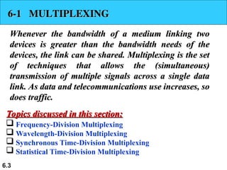
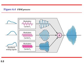
6.1
Chapter 6
Bandwidth Utilization:
Multiplexing and
Spreading
Copyright © The McGraw-Hill Companies, Inc. Permission required for reproduction or display.
6.2
Bandwidth utilization is the wise use of
available bandwidth to achieve
specific goals.
Efficiency can be achieved by
multiplexing; i.e., sharing of the
bandwidth between multiple users.
Note
6.3
6-1 MULTIPLEXING
6-1 MULTIPLEXING
Whenever the bandwidth of a medium linking two
devices is greater than the bandwidth needs of the
devices, the link can be shared. Multiplexing is the set
of techniques that allows the (simultaneous)
transmission of multiple signals across a single data
link. As data and telecommunications use increases, so
does traffic.
does traffic.
 Frequency-Division Multiplexing
 Wavelength-Division Multiplexing
 Synchronous Time-Division Multiplexing
 Statistical Time-Division Multiplexing
Topics discussed in this section:
6.4
Figure 6.1 Dividing a link into channels
6.5
Figure 6.2 Categories of multiplexing
6.6
Figure 6.3 Frequency-division multiplexing (FDM)
6.7
FDM is an analog multiplexing technique
that combines analog signals.
It uses the concept of modulation
discussed in Ch 5.
Note
6.8
Figure 6.4 FDM process
6.9
FM
6.10
Figure 6.5 FDM demultiplexing example
6.11
Assume that a voice channel occupies a bandwidth of 4
kHz. We need to combine three voice channels into a link
with a bandwidth of 12 kHz, from 20 to 32 kHz. Show the
configuration, using the frequency domain. Assume there
are no guard bands.
Solution
We shift (modulate) each of the three voice channels to a
different bandwidth, as shown in Figure 6.6. We use the
20- to 24-kHz bandwidth for the first channel, the 24- to
28-kHz bandwidth for the second channel, and the 28- to
32-kHz bandwidth for the third one. Then we combine
them as shown in Figure 6.6.
Example 6.1
6.12
Figure 6.6 Example 6.1
6.13
Five channels, each with a 100-kHz bandwidth, are to be
multiplexed together. What is the minimum bandwidth of
the link if there is a need for a guard band of 10 kHz
between the channels to prevent interference?
Solution
For five channels, we need at least four guard bands.
This means that the required bandwidth is at least
5 × 100 + 4 × 10 = 540 kHz,
as shown in Figure 6.7.
Example 6.2
6.14
Figure 6.7 Example 6.2
6.15
Four data channels (digital), each transmitting at 1
Mbps, use a satellite channel of 1 MHz. Design an
appropriate configuration, using FDM.
Solution
The satellite channel is analog. We divide it into four
channels, each channel having 1M/4=250-kHz
bandwidth.
Each digital channel of 1 Mbps must be transmitted over
a 250KHz channel. Assuming no noise we can use
Nyquist to get:
C = 1Mbps = 2x250K x log2 L -> L = 4 or n = 2 bits/signal
element.
One solution is 4-QAM modulation. In Figure 6.8 we
show a possible configuration with L = 16.
Example 6.3
6.16
Figure 6.8 Example 6.3
6.17
Figure 6.9 Analog hierarchy
6.18
The Advanced Mobile Phone System (AMPS) uses two
bands. The first band of 824 to 849 MHz is used for
sending, and 869 to 894 MHz is used for receiving.
Each user has a bandwidth of 30 kHz in each direction.
How many people can use their cellular phones
simultaneously?
Solution
Each band is 25 MHz. If we divide 25 MHz by 30 kHz, we
get 833.33. In reality, the band is divided into 832
channels. Of these, 42 channels are used for control,
which means only 790 channels are available for cellular
phone users.
Example 6.4
6.19
Figure 6.10 Wavelength-division multiplexing (WDM)
6.20
WDM is an analog multiplexing
technique to combine optical signals.
Note
6.21
Figure 6.11 Prisms in wavelength-division multiplexing and demultiplexing
6.22
Figure 6.12 Time Division Multiplexing (TDM)
6.23
TDM is a digital multiplexing technique
for combining several low-rate digital
channels into one high-rate one.
Note
6.24
Figure 6.13 Synchronous time-division multiplexing
6.25
In synchronous TDM, the data rate
of the link is n times faster, and the unit
duration is n times shorter.
Note
6.26
In Figure 6.13, the data rate for each one of the 3 input
connection is 1 kbps. If 1 bit at a time is multiplexed (a
unit is 1 bit), what is the duration of (a) each input slot,
(b) each output slot, and (c) each frame?
Solution
We can answer the questions as follows:
a. The data rate of each input connection is 1 kbps. This
means that the bit duration is 1/1000 s or 1 ms. The
duration of the input time slot is 1 ms (same as bit
duration).
Example 6.5
6.27
b. The duration of each output time slot is one-third of
the input time slot. This means that the duration of the
output time slot is 1/3 ms.
c. Each frame carries three output time slots. So the
duration of a frame is 3 × 1/3 ms, or 1 ms.
Note: The duration of a frame is the same as the duration
of an input unit.
Example 6.5 (continued)
6.28
Figure 6.14 shows synchronous TDM with 4 1Mbps data
stream inputs and one data stream for the output. The
unit of data is 1 bit. Find (a) the input bit duration, (b)
the output bit duration, (c) the output bit rate, and (d) the
output frame rate.
Solution
We can answer the questions as follows:
a. The input bit duration is the inverse of the bit rate:
1/1 Mbps = 1 μs.
b. The output bit duration is one-fourth of the input bit
duration, or ¼ μs.
Example 6.6
6.29
c. The output bit rate is the inverse of the output bit
duration or 1/(4μs) or 4 Mbps. This can also be
deduced from the fact that the output rate is 4 times as
fast as any input rate; so the output rate = 4 × 1 Mbps
= 4 Mbps.
d. The frame rate is always the same as any input rate. So
the frame rate is 1,000,000 frames per second.
Because we are sending 4 bits in each frame, we can
verify the result of the previous question by
multiplying the frame rate by the number of bits per
frame.
Example 6.6 (continued)
6.30
Figure 6.14 Example 6.6
6.31
Four 1-kbps connections are multiplexed together. A unit
is 1 bit. Find (a) the duration of 1 bit before multiplexing,
(b) the transmission rate of the link, (c) the duration of a
time slot, and (d) the duration of a frame.
Solution
We can answer the questions as follows:
a. The duration of 1 bit before multiplexing is 1 / 1 kbps,
or 0.001 s (1 ms).
b. The rate of the link is 4 times the rate of a connection,
or 4 kbps.
Example 6.7
6.32
c. The duration of each time slot is one-fourth of the
duration of each bit before multiplexing, or 1/4 ms or
250 μs. Note that we can also calculate this from the
data rate of the link, 4 kbps. The bit duration is the
inverse of the data rate, or 1/4 kbps or 250 μs.
d. The duration of a frame is always the same as the
duration of a unit before multiplexing, or 1 ms. We
can also calculate this in another way. Each frame in
this case has four time slots. So the duration of a
frame is 4 times 250 μs, or 1 ms.
Example 6.7 (continued)
6.33
Interleaving
 The process of taking a group
of bits from each input line
for multiplexing is called
interleaving.
 We interleave bits (1 - n)
from each input onto one
output.
6.34
Figure 6.15 Interleaving
6.35
Four channels are multiplexed using TDM. If each
channel sends 100 bytes /s and we multiplex 1 byte per
channel, show the frame traveling on the link, the size of
the frame, the duration of a frame, the frame rate, and
the bit rate for the link.
Solution
The multiplexer is shown in Figure 6.16. Each frame
carries 1 byte from each channel; the size of each frame,
therefore, is 4 bytes, or 32 bits. Because each channel is
sending 100 bytes/s and a frame carries 1 byte from each
channel, the frame rate must be 100 frames per second.
The bit rate is 100 × 32, or 3200 bps.
Example 6.8
6.36
Figure 6.16 Example 6.8
6.37
A multiplexer combines four 100-kbps channels using a
time slot of 2 bits. Show the output with four arbitrary
inputs. What is the frame rate? What is the frame
duration? What is the bit rate? What is the bit duration?
Solution
Figure 6.17 shows the output (4x100kbps) for four
arbitrary inputs. The link carries 400K/(2x4)=50,000
2x4=8bit frames per second. The frame duration is
therefore 1/50,000 s or 20 μs. The bit duration on the
output link is 1/400,000 s, or 2.5 μs.
Example 6.9
6.38
Figure 6.17 Example 6.9
6.39
Data Rate Management
 Not all input links maybe have
the same data rate.
 Some links maybe slower. There
maybe several different input
link speeds
 There are three strategies that
can be used to overcome the
data rate mismatch: multilevel,
multislot and pulse stuffing
6.40
Data rate matching
 Multilevel: used when the data rate of
the input links are multiples of each
other.
 Multislot: used when there is a GCD
between the data rates. The higher bit
rate channels are allocated more slots
per frame, and the output frame rate is
a multiple of each input link.
 Pulse Stuffing: used when there is no
GCD between the links. The slowest speed
link will be brought up to the speed of
the other links by bit insertion, this
is called pulse stuffing.
6.41
Figure 6.19 Multilevel multiplexing
6.42
Figure 6.20 Multiple-slot multiplexing
6.43
Figure 6.21 Pulse stuffing
6.44
Synchronization
 To ensure that the receiver correctly
reads the incoming bits, i.e., knows
the incoming bit boundaries to
interpret a “1” and a “0”, a known bit
pattern is used between the frames.
 The receiver looks for the anticipated
bit and starts counting bits till the
end of the frame.
 Then it starts over again with the
reception of another known bit.
 These bits (or bit patterns) are
called synchronization bit(s).
 They are part of the overhead of
transmission.
6.45
Figure 6.22 Framing bits
6.46
We have four sources, each creating 250 8-bit characters
per second. If the interleaved unit is a character and 1
synchronizing bit is added to each frame, find (a) the data
rate of each source, (b) the duration of each character in
each source, (c) the frame rate, (d) the duration of each
frame, (e) the number of bits in each frame, and (f) the
data rate of the link.
Solution
We can answer the questions as follows:
a. The data rate of each source is 250 × 8 = 2000 bps = 2
kbps.
Example 6.10
6.47
b. Each source sends 250 characters per second;
therefore, the duration of a character is 1/250 s, or
4 ms.
c. Each frame has one character from each source,
which means the link needs to send 250 frames per
second to keep the transmission rate of each source.
d. The duration of each frame is 1/250 s, or 4 ms. Note
that the duration of each frame is the same as the
duration of each character coming from each source.
e. Each frame carries 4 characters and 1 extra
synchronizing bit. This means that each frame is
4 × 8 + 1 = 33 bits.
Example 6.10 (continued)
6.48
Two channels, one with a bit rate of 100 kbps and
another with a bit rate of 200 kbps, are to be multiplexed.
How this can be achieved? What is the frame rate? What
is the frame duration? What is the bit rate of the link?
Solution
We can allocate one slot to the first channel and two slots
to the second channel. Each frame carries 3 bits. The
frame rate is 100,000 frames per second because it carries
1 bit from the first channel. The bit rate is 100,000
frames/s × 3 bits per frame, or 300 kbps.
Example 6.11
6.49
Figure 6.23 Digital hierarchy
6.50
Table 6.1 DS and T line rates
6.51
Figure 6.24 T-1 line for multiplexing telephone lines
6.52
Figure 6.25 T-1 frame structure
6.53
Table 6.2 E line rates
6.54
Inefficient use of
Bandwidth
 Sometimes an input link may
have no data to transmit.
 When that happens, one or
more slots on the output link
will go unused.
 That is wasteful of
bandwidth.
6.55
Figure 6.18 Empty slots
6.56
Figure 6.26 TDM slot comparison

Bandwidth Utilization in Networkings.ppt

  • 1.
    6.1 Chapter 6 Bandwidth Utilization: Multiplexingand Spreading Copyright © The McGraw-Hill Companies, Inc. Permission required for reproduction or display.
  • 2.
    6.2 Bandwidth utilization isthe wise use of available bandwidth to achieve specific goals. Efficiency can be achieved by multiplexing; i.e., sharing of the bandwidth between multiple users. Note
  • 3.
    6.3 6-1 MULTIPLEXING 6-1 MULTIPLEXING Wheneverthe bandwidth of a medium linking two Whenever the bandwidth of a medium linking two devices is greater than the bandwidth needs of the devices is greater than the bandwidth needs of the devices, the link can be shared. Multiplexing is the set devices, the link can be shared. Multiplexing is the set of techniques that allows the (simultaneous) of techniques that allows the (simultaneous) transmission of multiple signals across a single data transmission of multiple signals across a single data link. As data and telecommunications use increases, so link. As data and telecommunications use increases, so does traffic. does traffic.  Frequency-Division Multiplexing  Wavelength-Division Multiplexing  Synchronous Time-Division Multiplexing  Statistical Time-Division Multiplexing Topics discussed in this section: Topics discussed in this section:
  • 4.
    6.4 Figure 6.1 Dividinga link into channels
  • 5.
  • 6.
  • 7.
    6.7 FDM is ananalog multiplexing technique that combines analog signals. It uses the concept of modulation discussed in Ch 5. Note
  • 8.
  • 9.
  • 10.
    6.10 Figure 6.5 FDMdemultiplexing example
  • 11.
    6.11 Assume that avoice channel occupies a bandwidth of 4 kHz. We need to combine three voice channels into a link with a bandwidth of 12 kHz, from 20 to 32 kHz. Show the configuration, using the frequency domain. Assume there are no guard bands. Solution We shift (modulate) each of the three voice channels to a different bandwidth, as shown in Figure 6.6. We use the 20- to 24-kHz bandwidth for the first channel, the 24- to 28-kHz bandwidth for the second channel, and the 28- to 32-kHz bandwidth for the third one. Then we combine them as shown in Figure 6.6. Example 6.1
  • 12.
  • 13.
    6.13 Five channels, eachwith a 100-kHz bandwidth, are to be multiplexed together. What is the minimum bandwidth of the link if there is a need for a guard band of 10 kHz between the channels to prevent interference? Solution For five channels, we need at least four guard bands. This means that the required bandwidth is at least 5 × 100 + 4 × 10 = 540 kHz, as shown in Figure 6.7. Example 6.2
  • 14.
  • 15.
    6.15 Four data channels(digital), each transmitting at 1 Mbps, use a satellite channel of 1 MHz. Design an appropriate configuration, using FDM. Solution The satellite channel is analog. We divide it into four channels, each channel having 1M/4=250-kHz bandwidth. Each digital channel of 1 Mbps must be transmitted over a 250KHz channel. Assuming no noise we can use Nyquist to get: C = 1Mbps = 2x250K x log2 L -> L = 4 or n = 2 bits/signal element. One solution is 4-QAM modulation. In Figure 6.8 we show a possible configuration with L = 16. Example 6.3
  • 16.
  • 17.
  • 18.
    6.18 The Advanced MobilePhone System (AMPS) uses two bands. The first band of 824 to 849 MHz is used for sending, and 869 to 894 MHz is used for receiving. Each user has a bandwidth of 30 kHz in each direction. How many people can use their cellular phones simultaneously? Solution Each band is 25 MHz. If we divide 25 MHz by 30 kHz, we get 833.33. In reality, the band is divided into 832 channels. Of these, 42 channels are used for control, which means only 790 channels are available for cellular phone users. Example 6.4
  • 19.
  • 20.
    6.20 WDM is ananalog multiplexing technique to combine optical signals. Note
  • 21.
    6.21 Figure 6.11 Prismsin wavelength-division multiplexing and demultiplexing
  • 22.
    6.22 Figure 6.12 TimeDivision Multiplexing (TDM)
  • 23.
    6.23 TDM is adigital multiplexing technique for combining several low-rate digital channels into one high-rate one. Note
  • 24.
    6.24 Figure 6.13 Synchronoustime-division multiplexing
  • 25.
    6.25 In synchronous TDM,the data rate of the link is n times faster, and the unit duration is n times shorter. Note
  • 26.
    6.26 In Figure 6.13,the data rate for each one of the 3 input connection is 1 kbps. If 1 bit at a time is multiplexed (a unit is 1 bit), what is the duration of (a) each input slot, (b) each output slot, and (c) each frame? Solution We can answer the questions as follows: a. The data rate of each input connection is 1 kbps. This means that the bit duration is 1/1000 s or 1 ms. The duration of the input time slot is 1 ms (same as bit duration). Example 6.5
  • 27.
    6.27 b. The durationof each output time slot is one-third of the input time slot. This means that the duration of the output time slot is 1/3 ms. c. Each frame carries three output time slots. So the duration of a frame is 3 × 1/3 ms, or 1 ms. Note: The duration of a frame is the same as the duration of an input unit. Example 6.5 (continued)
  • 28.
    6.28 Figure 6.14 showssynchronous TDM with 4 1Mbps data stream inputs and one data stream for the output. The unit of data is 1 bit. Find (a) the input bit duration, (b) the output bit duration, (c) the output bit rate, and (d) the output frame rate. Solution We can answer the questions as follows: a. The input bit duration is the inverse of the bit rate: 1/1 Mbps = 1 μs. b. The output bit duration is one-fourth of the input bit duration, or ¼ μs. Example 6.6
  • 29.
    6.29 c. The outputbit rate is the inverse of the output bit duration or 1/(4μs) or 4 Mbps. This can also be deduced from the fact that the output rate is 4 times as fast as any input rate; so the output rate = 4 × 1 Mbps = 4 Mbps. d. The frame rate is always the same as any input rate. So the frame rate is 1,000,000 frames per second. Because we are sending 4 bits in each frame, we can verify the result of the previous question by multiplying the frame rate by the number of bits per frame. Example 6.6 (continued)
  • 30.
  • 31.
    6.31 Four 1-kbps connectionsare multiplexed together. A unit is 1 bit. Find (a) the duration of 1 bit before multiplexing, (b) the transmission rate of the link, (c) the duration of a time slot, and (d) the duration of a frame. Solution We can answer the questions as follows: a. The duration of 1 bit before multiplexing is 1 / 1 kbps, or 0.001 s (1 ms). b. The rate of the link is 4 times the rate of a connection, or 4 kbps. Example 6.7
  • 32.
    6.32 c. The durationof each time slot is one-fourth of the duration of each bit before multiplexing, or 1/4 ms or 250 μs. Note that we can also calculate this from the data rate of the link, 4 kbps. The bit duration is the inverse of the data rate, or 1/4 kbps or 250 μs. d. The duration of a frame is always the same as the duration of a unit before multiplexing, or 1 ms. We can also calculate this in another way. Each frame in this case has four time slots. So the duration of a frame is 4 times 250 μs, or 1 ms. Example 6.7 (continued)
  • 33.
    6.33 Interleaving  The processof taking a group of bits from each input line for multiplexing is called interleaving.  We interleave bits (1 - n) from each input onto one output.
  • 34.
  • 35.
    6.35 Four channels aremultiplexed using TDM. If each channel sends 100 bytes /s and we multiplex 1 byte per channel, show the frame traveling on the link, the size of the frame, the duration of a frame, the frame rate, and the bit rate for the link. Solution The multiplexer is shown in Figure 6.16. Each frame carries 1 byte from each channel; the size of each frame, therefore, is 4 bytes, or 32 bits. Because each channel is sending 100 bytes/s and a frame carries 1 byte from each channel, the frame rate must be 100 frames per second. The bit rate is 100 × 32, or 3200 bps. Example 6.8
  • 36.
  • 37.
    6.37 A multiplexer combinesfour 100-kbps channels using a time slot of 2 bits. Show the output with four arbitrary inputs. What is the frame rate? What is the frame duration? What is the bit rate? What is the bit duration? Solution Figure 6.17 shows the output (4x100kbps) for four arbitrary inputs. The link carries 400K/(2x4)=50,000 2x4=8bit frames per second. The frame duration is therefore 1/50,000 s or 20 μs. The bit duration on the output link is 1/400,000 s, or 2.5 μs. Example 6.9
  • 38.
  • 39.
    6.39 Data Rate Management Not all input links maybe have the same data rate.  Some links maybe slower. There maybe several different input link speeds  There are three strategies that can be used to overcome the data rate mismatch: multilevel, multislot and pulse stuffing
  • 40.
    6.40 Data rate matching Multilevel: used when the data rate of the input links are multiples of each other.  Multislot: used when there is a GCD between the data rates. The higher bit rate channels are allocated more slots per frame, and the output frame rate is a multiple of each input link.  Pulse Stuffing: used when there is no GCD between the links. The slowest speed link will be brought up to the speed of the other links by bit insertion, this is called pulse stuffing.
  • 41.
  • 42.
  • 43.
  • 44.
    6.44 Synchronization  To ensurethat the receiver correctly reads the incoming bits, i.e., knows the incoming bit boundaries to interpret a “1” and a “0”, a known bit pattern is used between the frames.  The receiver looks for the anticipated bit and starts counting bits till the end of the frame.  Then it starts over again with the reception of another known bit.  These bits (or bit patterns) are called synchronization bit(s).  They are part of the overhead of transmission.
  • 45.
  • 46.
    6.46 We have foursources, each creating 250 8-bit characters per second. If the interleaved unit is a character and 1 synchronizing bit is added to each frame, find (a) the data rate of each source, (b) the duration of each character in each source, (c) the frame rate, (d) the duration of each frame, (e) the number of bits in each frame, and (f) the data rate of the link. Solution We can answer the questions as follows: a. The data rate of each source is 250 × 8 = 2000 bps = 2 kbps. Example 6.10
  • 47.
    6.47 b. Each sourcesends 250 characters per second; therefore, the duration of a character is 1/250 s, or 4 ms. c. Each frame has one character from each source, which means the link needs to send 250 frames per second to keep the transmission rate of each source. d. The duration of each frame is 1/250 s, or 4 ms. Note that the duration of each frame is the same as the duration of each character coming from each source. e. Each frame carries 4 characters and 1 extra synchronizing bit. This means that each frame is 4 × 8 + 1 = 33 bits. Example 6.10 (continued)
  • 48.
    6.48 Two channels, onewith a bit rate of 100 kbps and another with a bit rate of 200 kbps, are to be multiplexed. How this can be achieved? What is the frame rate? What is the frame duration? What is the bit rate of the link? Solution We can allocate one slot to the first channel and two slots to the second channel. Each frame carries 3 bits. The frame rate is 100,000 frames per second because it carries 1 bit from the first channel. The bit rate is 100,000 frames/s × 3 bits per frame, or 300 kbps. Example 6.11
  • 49.
  • 50.
    6.50 Table 6.1 DSand T line rates
  • 51.
    6.51 Figure 6.24 T-1line for multiplexing telephone lines
  • 52.
    6.52 Figure 6.25 T-1frame structure
  • 53.
    6.53 Table 6.2 Eline rates
  • 54.
    6.54 Inefficient use of Bandwidth Sometimes an input link may have no data to transmit.  When that happens, one or more slots on the output link will go unused.  That is wasteful of bandwidth.
  • 55.
  • 56.
    6.56 Figure 6.26 TDMslot comparison