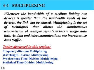
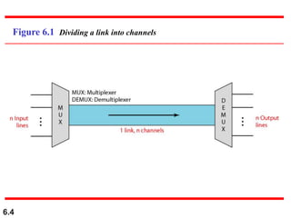
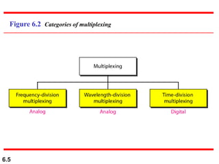
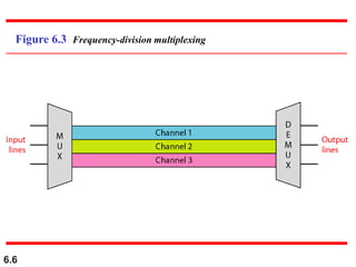
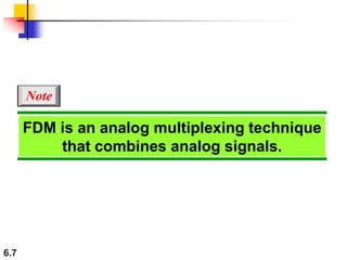
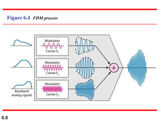
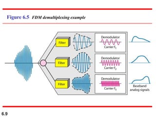
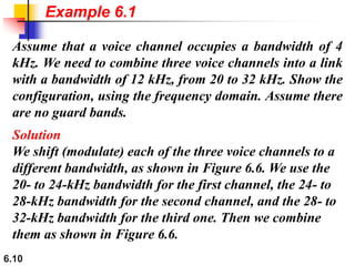
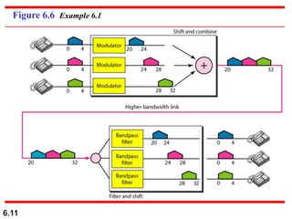
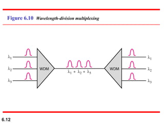
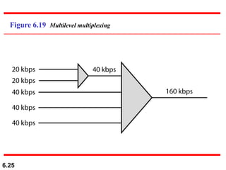
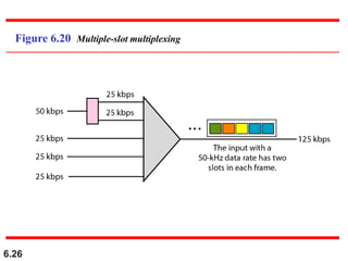
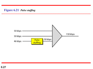
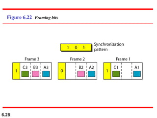
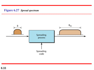
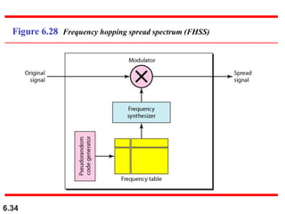
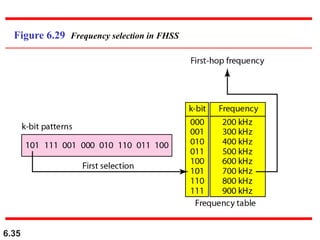
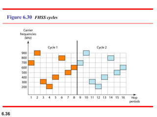
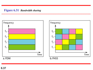
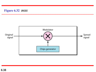
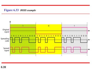
6.1
Chapter 6
Bandwidth Utilization:
Multiplexing and
Spreading
Copyright © The McGraw-Hill Companies, Inc. Permission required for reproduction or display.
6.2
Bandwidth utilization is the wise use of
available bandwidth to achieve
specific goals.
Efficiency can be achieved by
multiplexing; privacy and anti-jamming
can be achieved by spreading.
Note
6.3
6-1 MULTIPLEXING
Whenever the bandwidth of a medium linking two
devices is greater than the bandwidth needs of the
devices, the link can be shared. Multiplexing is the set
of techniques that allows the simultaneous
transmission of multiple signals across a single data
link. As data and telecommunications use increases, so
does traffic.
Frequency-Division Multiplexing
Wavelength-Division Multiplexing
Synchronous Time-Division Multiplexing
Statistical Time-Division Multiplexing
Topics discussed in this section:
6.4
Figure 6.1 Dividing a link into channels
6.5
Figure 6.2 Categories of multiplexing
6.6
Figure 6.3 Frequency-division multiplexing
6.7
FDM is an analog multiplexing technique
that combines analog signals.
Note
6.8
Figure 6.4 FDM process
6.9
Figure 6.5 FDM demultiplexing example
6.10
Assume that a voice channel occupies a bandwidth of 4
kHz. We need to combine three voice channels into a link
with a bandwidth of 12 kHz, from 20 to 32 kHz. Show the
configuration, using the frequency domain. Assume there
are no guard bands.
Solution
We shift (modulate) each of the three voice channels to a
different bandwidth, as shown in Figure 6.6. We use the
20- to 24-kHz bandwidth for the first channel, the 24- to
28-kHz bandwidth for the second channel, and the 28- to
32-kHz bandwidth for the third one. Then we combine
them as shown in Figure 6.6.
Example 6.1
6.11
Figure 6.6 Example 6.1
6.12
Figure 6.10 Wavelength-division multiplexing
6.13
WDM is an analog multiplexing
technique to combine optical signals.
Note
6.14
Figure 6.11 Prisms in wavelength-division multiplexing and demultiplexing
6.15
Figure 6.12 TDM
6.16
TDM is a digital multiplexing technique
for combining several low-rate
channels into one high-rate one.
Note
6.17
Figure 6.13 Synchronous time-division multiplexing
6.18
In synchronous TDM, the data rate
of the link is n times faster, and the unit
duration is n times shorter.
Note
6.19
In Figure 6.13, the data rate for each input connection is
1 kbps. If 1 bit at a time is multiplexed (a unit is 1 bit),
what is the duration of (a) each input slot, (b) each output
slot, and (c) each frame?
Solution
We can answer the questions as follows:
a. The data rate of each input connection is 1 kbps. This
means that the bit duration is 1/1000 s or 1 ms. The
duration of the input time slot is 1 ms (same as bit
duration).
Example 6.5
6.20
b. The duration of each output time slot is one-third of
the input time slot. This means that the duration of the
output time slot is 1/3 ms.
c. Each frame carries three output time slots. So the
duration of a frame is 3 × 1/3 ms, or 1 ms. The
duration of a frame is the same as the duration of an
input unit.
Example 6.5 (continued)
6.21
Four 1-kbps connections are multiplexed together. A unit
is 1 bit. Find (a) the duration of 1 bit before multiplexing,
(b) the transmission rate of the link, (c) the duration of a
output time slot, and (d) the duration of a frame.
Solution
We can answer the questions as follows:
a. The duration of 1 bit before multiplexing is 1 / 1 kbps,
or 0.001 s (1 ms).
b. The rate of the link is 4 times the rate of a connection,
or 4 kbps.
Example 6.7
6.22
c. The duration of each time slot is one-fourth of the
duration of each bit before multiplexing, or 1/4 ms or
250 μs. Note that we can also calculate this from the
data rate of the link, 4 kbps. The bit duration is the
inverse of the data rate, or 1/4 kbps or 250 μs.
d. The duration of a frame is always the same as the
duration of a unit before multiplexing, or 1 ms. We
can also calculate this in another way. Each frame in
this case has four time slots. So the duration of a
frame is 4 times 250 μs, or 1 ms.
Example 6.7 (continued)
6.23
Figure 6.15 Interleaving
6.24
Figure 6.18 Empty slots
6.25
Figure 6.19 Multilevel multiplexing
6.26
Figure 6.20 Multiple-slot multiplexing
6.27
Figure 6.21 Pulse stuffing
6.28
Figure 6.22 Framing bits
6.29
We have four sources, each creating 250 characters per
second. If the interleaved unit is a character and 1
synchronizing bit is added to each frame, find (a) the data
rate of each source, (b) the duration of each character in
each source, (c) the frame rate, (d) the duration of each
frame, (e) the number of bits in each frame, and (f) the
data rate of the link.
Solution
We can answer the questions as follows:
a. The data rate of each source is 250 × 8 = 2000 bps = 2
kbps.
Example 6.10
6.30
b. Each source sends 250 characters per second;
therefore, the duration of a character is 1/250 s, or
4 ms.
c. Each frame has one character from each source,
which means the link needs to send 250 frames per
second to keep the transmission rate of each source.
d. The duration of each frame is 1/250 s, or 4 ms. Note
that the duration of each frame is the same as the
duration of each character coming from each source.
e. Each frame carries 4 characters and 1 extra
synchronizing bit. This means that each frame is
4 × 8 + 1 = 33 bits.
Example 6.10 (continued)
6.31
Figure 6.26 TDM slot comparison
6.32
6-1 SPREAD SPECTRUM
In spread spectrum (SS), we combine signals from
different sources to fit into a larger bandwidth, but our
goals are to prevent eavesdropping and jamming. To
achieve these goals, spread spectrum techniques add
redundancy.
Frequency Hopping Spread Spectrum (FHSS)
Direct Sequence Spread Spectrum Synchronous (DSSS)
Topics discussed in this section:
6.33
Figure 6.27 Spread spectrum
6.34
Figure 6.28 Frequency hopping spread spectrum (FHSS)
6.35
Figure 6.29 Frequency selection in FHSS
6.36
Figure 6.30 FHSS cycles
6.37
Figure 6.31 Bandwidth sharing
6.38
Figure 6.32 DSSS
6.39
Figure 6.33 DSSS example

Ch06

  • 1.
    6.1 Chapter 6 Bandwidth Utilization: Multiplexingand Spreading Copyright © The McGraw-Hill Companies, Inc. Permission required for reproduction or display.
  • 2.
    6.2 Bandwidth utilization isthe wise use of available bandwidth to achieve specific goals. Efficiency can be achieved by multiplexing; privacy and anti-jamming can be achieved by spreading. Note
  • 3.
    6.3 6-1 MULTIPLEXING Whenever thebandwidth of a medium linking two devices is greater than the bandwidth needs of the devices, the link can be shared. Multiplexing is the set of techniques that allows the simultaneous transmission of multiple signals across a single data link. As data and telecommunications use increases, so does traffic. Frequency-Division Multiplexing Wavelength-Division Multiplexing Synchronous Time-Division Multiplexing Statistical Time-Division Multiplexing Topics discussed in this section:
  • 4.
    6.4 Figure 6.1 Dividinga link into channels
  • 5.
  • 6.
  • 7.
    6.7 FDM is ananalog multiplexing technique that combines analog signals. Note
  • 8.
  • 9.
    6.9 Figure 6.5 FDMdemultiplexing example
  • 10.
    6.10 Assume that avoice channel occupies a bandwidth of 4 kHz. We need to combine three voice channels into a link with a bandwidth of 12 kHz, from 20 to 32 kHz. Show the configuration, using the frequency domain. Assume there are no guard bands. Solution We shift (modulate) each of the three voice channels to a different bandwidth, as shown in Figure 6.6. We use the 20- to 24-kHz bandwidth for the first channel, the 24- to 28-kHz bandwidth for the second channel, and the 28- to 32-kHz bandwidth for the third one. Then we combine them as shown in Figure 6.6. Example 6.1
  • 11.
  • 12.
  • 13.
    6.13 WDM is ananalog multiplexing technique to combine optical signals. Note
  • 14.
    6.14 Figure 6.11 Prismsin wavelength-division multiplexing and demultiplexing
  • 15.
  • 16.
    6.16 TDM is adigital multiplexing technique for combining several low-rate channels into one high-rate one. Note
  • 17.
    6.17 Figure 6.13 Synchronoustime-division multiplexing
  • 18.
    6.18 In synchronous TDM,the data rate of the link is n times faster, and the unit duration is n times shorter. Note
  • 19.
    6.19 In Figure 6.13,the data rate for each input connection is 1 kbps. If 1 bit at a time is multiplexed (a unit is 1 bit), what is the duration of (a) each input slot, (b) each output slot, and (c) each frame? Solution We can answer the questions as follows: a. The data rate of each input connection is 1 kbps. This means that the bit duration is 1/1000 s or 1 ms. The duration of the input time slot is 1 ms (same as bit duration). Example 6.5
  • 20.
    6.20 b. The durationof each output time slot is one-third of the input time slot. This means that the duration of the output time slot is 1/3 ms. c. Each frame carries three output time slots. So the duration of a frame is 3 × 1/3 ms, or 1 ms. The duration of a frame is the same as the duration of an input unit. Example 6.5 (continued)
  • 21.
    6.21 Four 1-kbps connectionsare multiplexed together. A unit is 1 bit. Find (a) the duration of 1 bit before multiplexing, (b) the transmission rate of the link, (c) the duration of a output time slot, and (d) the duration of a frame. Solution We can answer the questions as follows: a. The duration of 1 bit before multiplexing is 1 / 1 kbps, or 0.001 s (1 ms). b. The rate of the link is 4 times the rate of a connection, or 4 kbps. Example 6.7
  • 22.
    6.22 c. The durationof each time slot is one-fourth of the duration of each bit before multiplexing, or 1/4 ms or 250 μs. Note that we can also calculate this from the data rate of the link, 4 kbps. The bit duration is the inverse of the data rate, or 1/4 kbps or 250 μs. d. The duration of a frame is always the same as the duration of a unit before multiplexing, or 1 ms. We can also calculate this in another way. Each frame in this case has four time slots. So the duration of a frame is 4 times 250 μs, or 1 ms. Example 6.7 (continued)
  • 23.
  • 24.
  • 25.
  • 26.
  • 27.
  • 28.
  • 29.
    6.29 We have foursources, each creating 250 characters per second. If the interleaved unit is a character and 1 synchronizing bit is added to each frame, find (a) the data rate of each source, (b) the duration of each character in each source, (c) the frame rate, (d) the duration of each frame, (e) the number of bits in each frame, and (f) the data rate of the link. Solution We can answer the questions as follows: a. The data rate of each source is 250 × 8 = 2000 bps = 2 kbps. Example 6.10
  • 30.
    6.30 b. Each sourcesends 250 characters per second; therefore, the duration of a character is 1/250 s, or 4 ms. c. Each frame has one character from each source, which means the link needs to send 250 frames per second to keep the transmission rate of each source. d. The duration of each frame is 1/250 s, or 4 ms. Note that the duration of each frame is the same as the duration of each character coming from each source. e. Each frame carries 4 characters and 1 extra synchronizing bit. This means that each frame is 4 × 8 + 1 = 33 bits. Example 6.10 (continued)
  • 31.
    6.31 Figure 6.26 TDMslot comparison
  • 32.
    6.32 6-1 SPREAD SPECTRUM Inspread spectrum (SS), we combine signals from different sources to fit into a larger bandwidth, but our goals are to prevent eavesdropping and jamming. To achieve these goals, spread spectrum techniques add redundancy. Frequency Hopping Spread Spectrum (FHSS) Direct Sequence Spread Spectrum Synchronous (DSSS) Topics discussed in this section:
  • 33.
  • 34.
    6.34 Figure 6.28 Frequencyhopping spread spectrum (FHSS)
  • 35.
    6.35 Figure 6.29 Frequencyselection in FHSS
  • 36.
  • 37.
  • 38.
  • 39.