
Recommended
Recommended
More Related Content
What's hot
What's hot (20)
Viewers also liked
Viewers also liked (19)
Similar to Avanza wiring diagram
Similar to Avanza wiring diagram (20)
Recently uploaded
Recently uploaded (20)
Avanza wiring diagram
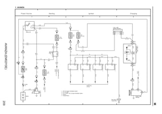
- 1. AVANZA(EM02Y0E) 209 M 1 2 3 4 1 AVANZA 1 1A IA1 10A E/G ID2 Charge FL MAIN 2. 0L 2 1 W–B 10A ECU IG2 W–G EngineECU <2–9> IGT (M/T) I6 1 W I4 BB 1 B–YB–RB AM25 6 ST2 IG2 1 1B1 40A AM1 B–W B B L A4 8 I 5 C5(B),C8(C) 1 A 1 B B 1C1 1 B–R 2 B 2 W W L–B W–RW–R G LG B B–R B 4 3 (A/T) 3 3 W–R P ow er S ource C harging ID15 I2 7. 5A ST–A 2 2 2 B–R A 3(A), A 4(B) S1(A),S2(B) 2 10 IA1 2 B–W +B GND (A/T) W–B Charge W (M/T) W Engine ECU <2–10> W W–B WLG–B I3 W W W–B 3 ED W–B IgnitionCoilNo.4 Rear Side of Engine Block Battery 1 2 2 1 Alternator CombinationMeter IgnitionCoilNo.2 IgnitionCoilNo.1 1 IgnitionCoilNo.3 Ignition SW Starter 39 C (A/T) 16 B (M/T) 14 B (M/T) 36 C (A/T) (A/T) B (M/T) 2 1 5 3 1 B 7. 5A (ST–B) 2 2 2 (A/T) BB B–R (A/T) B–Y (A/T) B–R Starter Relay S9 B (A/T) (M/T) W–B W–B W–B S tarting Ignition 2 A IG PEngineECU <2–9> 1 4414 1 4 W–L (A/T)EngineECU(∗7) <2–9> IGT +B GND GND+B IGT IGT +B GND ∗ 4 : A/T w/o SRS ∗ 6 : Mexico ∗ 7 : Except Mexico ∗ 5 : A/T w/ SRS, M/T w/ Engine Immobiliser System ∗ 1 : M/T w/o Engine Immobiliser System (∗1) LG (∗4, ∗5) LG AD BB A (∗4)D B (∗5)B Junction Connector J 2(A), J 8(B) (∗4, ∗5) LG (∗1) CombinationMeter(∗6) <3–5>
- 2. AVANZA(EM02Y0E) 210 MOVERALLELECTRICALWIRINGDIAGRAM 1 2 3 4 2 AVANZA (Cont. next page) 12 B–R PUMP– PUMP+ W–B R R A C39 2 B–RB–R 1 40AAM1 AM25 6 ST2 IG2 1B1 P ow er S ource D LC 3 2 1 15AEFI 2 2 2 2 13 2 1 2 I 5 Rear Quarter Panel RH BA 2 2 IF1 2 1 10ABACKUP 5 W–B(∗13) B 3 B–W B–R W B–W V–W W EFIRelay F/PRelay FL MAIN 2. 0L CheckEngine W 1 R B 19 ID1 ID22 1 10AE/G 2 Battery 2 B 13 ID1 LG(A/T, M/T ∗5) 2 10AECUIG2 2 D 1 R–B SIGE R–B(M/T∗13) W–B REV LG 9 EFITVF LG–B(∗13) LG 121 E 4 W–BW–B 5 G28 E 8(A), E 9(B), E10(C), E12(D), E13(E), E14(G), E15(F) V–W B–W B–R 16 +B B–R 6 C SIO C22 Cowl Side Panel LH (LHD) IC 7 LG–B EFIT VF W FC1(∗14, ∗16) FC3(∗15)SIO1 C27 CANL (A/T∗13) REV 1 2 5 3 1 2 1 1 2 W–B(∗13) W–B DLC3 Ignition SW Engine ECU V (w/ABS) V 13 ECUT CANH 14 SkidControlECU withActuator<9–4> V (A/T) Transmission ControlECU <3–2> V (w/SRS) CheckEngine 16 B (M/T) 37 C (A/T) (A/T) (M/T) (M/T)(M/T) (A/T) (A/T) W Transmission ControlECU <3–2>B 6 (A/T∗13) AirbagSensor AssemblyCenter <10–3> IA16 B–R B–RB–R B–R B–R V(∗5) LG(∗5) B–R(∗5)B–R B–R W–B 4 B (∗2) 3 A (∗1) 5 B (∗2) 4 A (∗1) Fuel Pump F15(A), F18(B) LG (M/T ∗9) 16 C (∗15) (∗16) V B–Y 4 BC1 5 BC1 AD BB B (∗5)B A (∗10)D B (M/T ∗5, ∗11)B LG (A/T,M/T∗5) LG (∗5) B LG(M/T ∗9) (∗5) (∗5) (∗8) ∗ 1 : w/o Fuel Level Warning Light ∗ 2 : w/ Fuel Level Warning Light ∗ 5 : w/ Engine Immobiliser System ∗ 9 : w/o Engine Immobiliser System ∗10 : A/T w/o SRS ∗11 : A/T w/ SRS ∗13 : Except Mexico ∗14 : Mexico ∗15 : RHD w/ Heater ∗16 : LHD Except Mexico, RHD w/o Heater Junction Connector J 2(A), J 8(B) Combination Meter<19–3> R–G(A/T) (M/T∗13) F (∗14)15 LG (A/T,M/T∗5) ∗ 8 : ∗5, A/T, w/ ABS, w/ SRS G–O(∗14) B B–R B–R (∗14) B W (∗13) (∗14) B B(∗14) W (∗14) W(∗14) G(∗14) G(∗14) R(∗14) R(∗14) CombinationMeter C4(A),C5(B),C8(C) (∗13) C28 G6 AirbagSensor AssemblyCenter <10–3> Transmission Control ECU<3–3> P–B (∗14) P–B (∗14) P–B (A/T∗14) P (∗13) P–B (∗5∗14) P–B(∗5 ∗14) G–O (∗14) (∗13) R–G(M/T∗14) B(∗13) R–G(M/T ∗14) (∗13) (∗14) C (∗13)25C17 (∗14) Right Kick Panel (RHD) E ngine C ontrol A B C D E F G H I J K L M
- 3. AVANZA(EM02Y0E) 211 M 7 865 (Cont. next page)2 AVANZA (Cont' d) (w/SRS∗13) SkidControlECU withActuator<9–4> B(∗13) G733 G R–B(A/T) R–G(M/T∗13) REV BAT AirbagSensor AssemblyCenter <10–3> SIO1 B SIO1 (w/ABS) C P–B 20 P–L 34 LG G–B OCV+ 7 B B–R VSV(Purge) B–R FuelInjectorNo.1 FuelInjectorNo.2 ThrottlePosition Sensor WaterTemperature Sensor FuelInjectorNo.3 Vacuum Sensor PowerSteering OilPressureSW FuelInjectorNo.4 Engine ECU VC E2 VTA V 1 3 V3 W1 T1 BR BR BR 2 A19 THW B–W BR E2 30 A 3 A20 VTH O L–R VC 10 A 11 E2 E2PM E29 1 W–B B–R B–R B–RW–G W–L W–R W(∗13) B–RB–RB–R D1D2D3 1 2 1 2 1 22 1 #10 #20 #30 #40 F8 F9 F10 F11 VCPM E R–W 32 A 17 2 1 7 D E ngine C ontrol G–R 12 E B–RB–R E 8(A), E 9(B), E10(C), E12(D), E13(E), E14(G), E15(F) PIMPRG +B1 32 PST L–W P1 PIM VC E B–R P–L 9 W(∗13) IA1 ∗13 : Except Mexico (∗4) OCV– 6 B 2 1 C7 CamshaftTimingOil ControlValve BR 2 1 GR OX1 2 A 3 4 BR H11 HeatedOxygenSensor (Bank1Sensor1) (∗4) L–Y OXH1 8 A 1 2 B–R BR B–R IACA LO IACA HI 15 D 14 D G–B G–O IACB HI 17 D R–B IACB LO 16 D R–L 2413 Idle Speed Control Actuator I 1 G–B LG 11 IA1 IA112 BR LG(∗5) B–R(∗5) LG(∗5) V(∗5) V(∗5) B–R(∗5) B–R ∗ 4 : Shielded ∗ 5 : Engine Immobiliser System BR (∗4) (∗14) OX E1 HT +B MRO G–O(∗14) 1 G 2 G 35 G IGSWHCANLCAN W(∗14) G(∗14) R(∗14) G (∗14) R (∗14) W (∗14) C7C24 D D Combination Meter <19–3><20–2> R–G R–G Junction Connector J 5 P–B(∗5 ∗14) A5 A4 B5 A9 A7 D4 A6 W (∗14) A12 A23 A22 P–B(∗5 ∗14) A15 A14 A25 A24 ∗14 : Mexico D6 D5 (∗13) (∗13)(∗13) (∗13) LG (∗14) G–B (∗14) 1 HT 3 OX 2 +B 4 E1 HeatedOxygenSensor (Bank1Sensor2) H12 OXH2 OX2 B–R (∗14) BR (∗14) (∗4) (∗14) W (∗14) P (∗14) C23 D12 C31 B B O BR–Y (∗13) BR (∗14) (∗13) BR–Y E21AUX JunctionConnector J6 (∗14) BR E2 E30 B–O (∗14) GR (∗14) E16 E13 E6 E14E31 (∗13) D (M/T ∗14) (M/T ∗14) B(∗14) B(∗13) B–R R–G(M/T ∗14) F6 7 F Transmission ControlECU <3–2> (A/T∗14) W B (A/T∗14) CANL CANH G8 E1 E5 (∗13) (∗14) (∗13) (∗14) B(∗14) G–O (∗14) G31 (∗14) AirConditionerSystem <21–4> Resistor R 5(A), (B) B (∗14)1 A (∗13)1 A (∗13)2 B (∗14)2 A B C D E F G H I J K L M A B C D E F G
- 4. AVANZA(EM02Y0E) 212 MOVERALLELECTRICALWIRINGDIAGRAM 9 10 11 12 2 AVANZA (Cont' d) ST–AFuse <1–1> B–R F26 STA W–R D8 IG4 W–G D9 IG3 FPOF C13 DEF HeadlightDimmerSW <6–1> R–L G10 StopLightSW <4–3> G–Y G12 H/L STP 2B3 B 1 B L–W R G L C4 W–G (w/SRS) Ignition Coils <1–2><1–3> L–B LG–B D10D11 IG1 IG2 ATNE ATTX ATRX ALT TransmissionControl ECU<3–3> AirbagSensorAssemblyCenter <10–3> RearWindowDefoggerSW <17–3> G–W THA 13 A BR I7 InletAir TemperatureSensor (A/T) (A/T∗13) (A/T∗13) 34 D PAlternator <1–4> 2 1 SPD 29 G LG–RCombinationMeter <19–2><20–2> A Crankshaft PositionSensor Camshaft PositionSensor A N2+ ∗ 5 : w/ Engine Immobiliser System (∗4) 1 2 29 A E ngine C ontrol BR–W R (∗4) F17F16 3 A BR BR MGC FAN1ACVR N2– E1 E01 BR–W B (∗4) W L A A21A11 1 2 31 A A KNK N1+ N1– F3G14 Air Conditioner System <21–4><22–4> ACEV ACSW G11 BLW C1 EBRear Side of Engine Block G A C2 E 8(A), E 9(B), E10(C), E12(D), E13(E), E14(G), E15(F) W (∗4) SEL W–B B4 Right Kick Panel (LHD) IA W–B A J 4 Junction Connector (A/T∗13)(A/T∗13) A (∗4) C C B B B Junction Connector J 1 Engine ECU BR B GR E ngine Immobiliser S ystem UnlockWarningSW <11–7><12–7> KSW 3 R–W T13 Transponder Key Coil T14 Transponder Key ECU ANT2ANT1 7 COIL(–) 13 1 COIL(+) 6 B–W GND 7 W–B Cowl Side Panel LH (LHD) 9 SIO1 10 T V 2 IG LG 8 1 +BSIO2 B–R ANT1 ANT2 B–R(∗5) V(∗5) LG(∗5) GR SIO2SIO1 P–GTransmission ControlECU <3–3>(A/T∗13) (∗5∗13) P–B (∗5∗13) P–B DoorControlReceiver <11–6><12–6> IND 14 L–W (∗12) StarterRelay <1–2> CombinationMeter <3–5> A/TA/T W–L (A/T∗13) (A/T∗13) W–R (∗4) (∗14) (w/oHeater) (∗5) (∗5) (∗5) (∗5) (∗5) ∗ 4 : Shielded ∗12 : w/ Rear Window Defogger A Junction Connector J 1 2 1 KnockControl Sensor K1 C18C12C10A26B15 E15 F4 G13 G4 A17 A27 A34 A16 E28 E19 E35 A18 E18 A28 E34 E32 E7 C11B24C14 B14B25 G (∗14)32 C (∗13)32 P–B(∗5 ∗14) P–B (∗5∗14) ∗13 : Except Mexico (∗13) (∗14) C9 C20 C30 C26 Left Kick Panel (RHD) Left Fender Apron (RHD) IE : LHD EC : RHD BR ∗14 : Mexico A B C D E F G
- 6. AVANZA(EM02Y0E) 214 MOVERALLELECTRICALWIRINGDIAGRAM 1 2 3 4 3 AVANZA (Cont. next page) L–B B–RB–R 1 40AAM1 AM25 6 ST2 IG2 1B1 P ow er S ource E C T and A /T Indicator 2 I 5 1 10A(ECU–B) B–W L–B LG FL MAIN 2. 0L B 2 ID1ID22 10AECUIG2 2 Battery 2 V 31 L–B B T 8(A), T 9(B), T10(C) B 6 LG B(∗3) A13 B18 BAT2 BRK ETMP +B1 B LG 1 2 1 1 2 Ignition SW Transmission Control ECU 7 B G–W R P A15 N A24 D A17 2 A16 G–O L A25 V ODL C2210 StopLightSW <4–3> P B15 SPDO CombinationMeter <19–2> G–B G–R B–L 11 A14 OTMP A12 SOLR A11 LUCR G–W A23 LUCC A3 C2– O A4 C2+ A1 C3B2– G A2 C3B2+ A5 B1– R–W A6 B1+ 7 W–GR 10 W–RY 5 B–WW 9 G–YL 2 B–YBR 3 L–RB 4 GRGR 8 Y–B 12 A VOUTVCC GND V C11 T P–B(∗2) P–G(∗3) B17 SIO1 L–W B8 REG1 EngineECU (∗3)<2–11> R B4 CRX DLC3 <2–3> G B12 CTX EngineECU <2–11> B11 CANG D D (∗1) BR Junction Connector J 3 ∗ 1 : Shielded A8 ROPT L ECT Solenoid E 3 A9 VBTB L–B A10 RTBN W BR–W B6 E01 B B5 E02 B B24 E1 B 2 IA1 G–O ED C C C T7 Transmission RevolutionSensor (OutputShaft) Transmission RevolutionSensor (FrontClutchDrum) T6 W–L P–B (∗1) (∗1) (∗1) (∗1) B B B B B Junction Connector J 3 L–O B–Y L–O 3 3 2 1 1 2 P–B ETBN 20 B22 O/D1 LG–R 4 3 O/DOffSW O6 A W–B GND VOUT VCC Rear Side of Engine Block 2 L–B B BAT1 CANH W(∗3) B20 CANL DLC3 <2–3> 18 EOPT W–L A7 VBOP L–Y LG Park/Neutral PositionSW<16–1> BB AD B (w/ SRS)B A (w/o SRS)D A (w/o SRS)D B (w/ SRS)B G–W G–W G–W R R Junction Connector J 2(A), J 8(B) ∗ 2 : Mexico ∗ 3 : Except Mexico EngineECU <2–8> W(∗2) B(∗2) G–Y (∗3) (∗3) (∗3) (∗3) DLC3(∗2)<2–2> (∗3) A B C D E F G H I
- 7. AVANZA(EM02Y0E) 215 M 7 865 3 AVANZA (Cont' d) L–O G–O B–L G–R G–B LG V Starter Relay (∗2)<1–2> W–L(∗2) W–R(∗3) 21 Junction Connector J 3 BV J2 JunctionConnector N 1 C 8 Combination Meter L–O 82354 6 V G–O B–L G–R G–B A CBA A B C AG–O A CBA B B G–W W–B BR Right Kick Panel (LHD) IA Cowl Side Panel LH (LHD) IC V G–O B–L G–R G–B BR 39 P N D L2 7 35 O/DOFF R 16 P N 22 23 D 24 2 25 L 26 E C T and A /T Indicator W–B W–B W–B A Park/Neutral Position SW J 4 Y–G BR–W Y–B G–Y G–W E W–B Junction Connector G–W Engine ECU (∗3)<2–9> ∗ 3 : Except Mexico ∗ 2 : Mexico Left Kick Panel (RHD) Right Kick Panel (RHD) A B C D E F G H I
- 8. AVANZA(EM02Y0E) 216 MOVERALLELECTRICALWIRINGDIAGRAM 1 2 3 4 4 AVANZA Battery B FL MAIN 2. 0L HEAD Relay 1 2 1 5 3 1 H 2 H 1 Dimmer SW Light Control SW 22 11 L R R–Y R–W B–LB–L R–W R–Y R–W R–Y R–Y 3 21 3 21 1 10A H–LP RH 1 10A H–LP LH 1B ELHUHLH High Low Flash ELHETT Head Tail OFF R–W 2 HighBeam R–Y ID14 R–Y B A6 B P ow er S ource H eadlight (M/T) R ID121 R–W BRBR W–B Right Kick Panel (LHD) IA Cowl Side Panel LH (LHD) G–R ID125 1 4 G–Y 2 Right Side of Back Door 2 1 G–YG–YG–Y G–YW–B W–B 5 5 2 2 BE1 W–B S top Light IF1 Rear Quarter Panel RH W–B W–B W–B BA G–Y EngineECU<2–9> BB 2 BD1 W–BW–B 1 6 BD1 G–Y G–Y W–B R7 S 3 Stop G–Y R6 Stop C6 (∗7) (∗7)(∗7) 2 1 G–R 1 10A STOP ∗ 7 : w/ Center Stop Light (M/T) CenterStopLight Headlight LH Headlight RH RearCombinationLightLH RearCombinationLightRH Stop Light SW B B G–Y G–Y A J 4 (w/ABS) G–YTransmissionControlECU <3–2> G–YSkidControlECU withActuator <9–4> (A/T∗8) G–Y G–Y CombinationMeter C4(A),C5(B) 16 R–Y (A/T) BR (A/T) CombinationMeter C8 2 IC Cowl Side Panel LH (LHD) HighBeam Junction Connector ∗ 8 : Except Mexico A A Junction Connector J 6 G–R BR 17 ID1 ID110 (LHD) (RHD) B6 A12 Headlight Dimmer SW H 8(A), (B) B10 A8 B (RHD)9 A (LHD)9 A (LHD)11 B (RHD)7 10 ID1 ID11 (LHD) (RHD) Left Kick Panel (RHD) Left Fender Apron (RHD) IE : LHD EC : RHD Right Kick Panel (RHD)
- 9. AVANZA(EM02Y0E) 217 M 1 2 3 4 5 AVANZA LG–B R–B RR B–R Battery B FL MAIN 2. 0L ID22 1 ID2 2 1 1 A 1B1 40AAM1 40AIG1 1 2 1 ACC IG1AM1 2 G–B 7.5AIG1/BACK L L–B 1 5 6 LH RH N 8 2 1 2 15AHAZARD BR 2 1 2 1 IB GW–B 3 2 5 3 5 3 2 G–B G BA W–B W–B Cowl Side Panel LH (LHD) ID1 4 1 +B IG EL ER EHW LL LR B–R B–Y P ow er S ource Turn S ignal and H azard W arning Light BR 2 W–B 7 GND TL TB TR R Cowl Side Panel LH (LHD) IC BR 3 W–B 4 G–B G 7 IF116 G–B W–B H 8(A), (B) R6 R7 I 5 G B H7 G IF115 Turn Turn TurnSignalSW 1 G G–B R 2 ∗ 1 : w/ Wireless Door Lock Control 2 1 2 W–B W–B W–B F6 F5 G–B 6 A TurnLH TurnRH C4(A),C5(B) R–B IARight Kick Panel (LHD) EARight Fender Apron W–B BR W–B Cowl Side Panel RH B–R Rear Quarter Panel RH CombinationMeter HazardWarningSignalSW FrontTurnSignal LightLH FrontTurnSignal LightRH Headlight Dimmer SW Ignition SW RearCombination LightLH RearCombination LightRH GB BG R (M/T) (M/T) W–B (M/T) A G–B G (A/T) (A/T) BR (A/T) TurnRH TurnLH G–B 16 5 1 DoorControlReceiver <11–6><12–6> ∗ 2 : w/o Wireless Door Lock Control ∗ 3 : w/ Front Side Turn Signal Light (∗1) Combination Meter C 8 Cowl Side Panel LH (LHD) CC C C Junction Connector J 6 C G–W (∗3) G–W (∗3) W–B (∗3) 1 2 F17 FrontSideTurn SignalLightRH (∗1)(∗1) Junction Connector J8 (∗2) R (∗3) G–B (∗3) W–B 1 2 F16 FrontSideTurn SignalLightLH A A A G–B G(A/T) G(M/T) BR Junction Connector J 4 Turn Signal Flasher T 2 B (RHD)12 A (LHD)6 A5 B11 A (LHD)7 B (RHD)13 1 ID1 ID118 (LHD) (RHD) Left Fender Apron (RHD) IE : LHD EC : RHD Left Kick Panel (RHD) Right Kick Panel (RHD) Left Fender Apron (RHD) IE : LHD EC : RHD
- 10. AVANZA(EM02Y0E) 218 MOVERALLELECTRICALWIRINGDIAGRAM 1 2 3 4 6 AVANZA 1 Battery B FL MAIN 2. 0L 2 Right Fender Apron BR 2 BE12 BR H7 W–B 1 W–B BE11 R3 10 1 R–L R–L IF13 1 Right Kick Panel (LHD) W–B BR W–B B5(A),(B) 1 10ATAIL 1B1 EA W–B BR Cowl Side Panel LH (LHD) Rear Quarter Panel RH R–L R–LBR R–LW–B R–L Rear Side of Back Door R–L R–LW–B W–B R–L IF1 W–B 21 R–L IA R6 1 2 7 Cowl Side Panel LH (LHD) R–L IC R–L R–L R–L R7 W–B BR BR P ow er S ource Taillight and Illumination 3 2 ID1 BD1 2 R–L 5 1 5 1 R–L IB Cowl Side Panel RH OFF Tail Head T ET BA 6 7 BD1 G–Y W–BW–B GND R–L ILL+ W–B 1 2 R–LR–L W–B G–Y W–B W–B BB L1 C4 W–B H8(A),(B) W–B Light ControlSW Tail R–L W–B Tail R–L Illumination 8 F2 F1 23 ID1 W–B 2 R–L W–B L2 R–L R–LR–LR–LR–L R–L Engine ECU <2–9> W–B BR CombinationMeter HazardWarningSignalSW FrontClearanceLightLH FrontClearanceLightRH BlowerSW HeadlightDimmerSW LicensePlateLightLH LicensePlateLightRH RearCombination LightLH RearCombination LightRH B BR–L R–L 2 1 W–BR–B A A RadioReceiver Illumination W–B (A/T) BR (A/T) R–L (A/T) R–L (A/T) 16 14 CombinationMeter C8 (M/T)(M/T) R–L BR (∗1) R–L R–L W–B H10 (∗1) (∗2) R14 W–B 1 2 (∗2) RearWindowDefoggerSW HeaterControl (AirInletSelectLeverIllumination) 1 2 WW BR W–B W–B R–L ∗ 4 : w/ Ash Receptacle Light ∗ 2 : w/ Rear Window Defogger ∗ 7 : w/ Radio Receiver ∗ 9 : w/o Heater ∗ 1 : w/ Air Inlet Select Lever Illumination (∗4) ∗ 8 : w/ Heater (∗4) BR (∗7)(∗7) (∗7) ∗10 : w/ A/C SW B (∗9)7 A (∗8)2 A (∗8)3 B (∗9)6 (M/T) W–B ∗ 3 : w/ Clock Junction Connector J 4 B (RHD)8 A (LHD)10 A (LHD)13 B (RHD)5 1 2 A12 A/CSW R–L (∗10) W–B (∗10) W–B Left Kick Panel (RHD) Right Kick Panel (RHD) Left Fender Apron (RHD) IE : LHD EC : RHD R–L AshReceptacleLight A7 C10 3 2 R–LW–B EARTH(–) ILL(+) Clock (∗3)(∗3)
- 11. AVANZA(EM02Y0E) 219 M 1 2 3 4 7 AVANZA W B B W R COMMVMH W–B 40AAM1 B–R AM1 IG1 ACC 1 P ow er S ource Fog Light R emote C ontrol M irror L3 Select SW OperationSW L R RL 1 5 3 1 5 3 G–R V G–R R–L G–B R–W R–L G–B R–W R–L R–W V B HL VL M+HR VR E R–L G–B 2 7. 5A ACC 2 R–L W–B L 763425 8 B Battery FL MAIN 2. 0L 2 B–R 1 1B1 1 2 1 2 5 3 2 Right Kick Panel (LHD) W–B IBCowl Side Panel RH 1 2 1 2 IA 2 R–G R–G W–B W–B L 2 O3 O4 O 2 F 4 F 3 R–G 2 I 5 2 ID2 B–R 6 ID1 W–B EARight Fender Apron W–B 1 1 10ATAIL G–YG–Y 23 ID1 2 1 1 15A(F–FOG) R–BR–B 12 ID1 2 (FOG) Relay W–B W–B 1 Down R COMMVMH W–B OuterRearView MirrorLH Front Fog Light LH Front Fog Light RH Ignition SW Outer Mirror SW OuterRearView MirrorRH M M MM UpRightLeft MH MV Right/ Down Left/ Up A J 4 Junction Connector On OFF OFF Tail Head ET T Light ControlSW BFG FFG FogSW R–L G–Y HeadlightDimmerSW H8(A),(B) B C C C Junction Connector J 5 R–B G–R B (RHD)5 A (LHD)13 A (LHD)2 B (RHD)1 A4 B3 A10 B8 10 IB1 IB25 4 IB1 IB22 3 IB1 IB210 5 IE1 IE210 2 IE1 IE24 10 IE1 IE23 (LHD) (RHD) (LHD) (RHD) Left Kick Panel (RHD)
- 12. AVANZA(EM02Y0E) 220 MOVERALLELECTRICALWIRINGDIAGRAM 1 2 3 4 8 AVANZA FL MAIN 2. 0L B Battery 2 3 1 L P ow er S ource 2 7. 5A ACC 2 BARear Quarter Panel RH W–B B–RB–R 1 1B1 40AAM1 1 2 2 ID2 1 B–R 4 L 1 B–R B(+)ACC(+) 5 ACC IG1 IG2 ST2 AM1 6AM2 Ignition SW I 5 2 2 10A ECU IG2 2 1B–W 16 B (M/T) 39 C (A/T) 2 EARTH(–) W–B9 C (A/T) 13 B (M/T) P–L B–Y S eat B elt W arning C lock 1 1 10ABACKUP 2 B–R Clock C10 2 1 8 IF1 P–LP–L Buckle SW (Driver' s Side) B 7 IARight Kick Panel (LHD) A Junction Connector J 4 L B (∗2)B A (∗1)D A (∗1)D B (∗2)B Junction Connector J 2(A), J 8(B) ∗ 1 : A/T w/o SRS A1 10AHORN 1 1 IB R–Y 1 2 5 3 11 HORN Relay 11 G–B R–B H orn 2 1 R–Y 1 1 B H3(A),H4(B) R–B B S8 H5(A),H6(B) A IAEARight Fender Apron W–B W–BW–B W–BR–B Cowl Side Panel RH SpiralCable Horn(High) Horn(Low) Horn A 1 G–B H9 HornSW 1 (∗15) G–B (∗14) ∗ 3 : w/ Wireless Door Lock Control IC Cowl Side Panel LH (LHD) BR CPU Driver's SeatBelt B–R ID119 40 C 16 C (A/T) B–R (A/T) Driver's SeatBelt Combination Meter C 5(B), C 8(C) (A/T) (A/T) IC (M/T)(M/T) B–R (A/T) B–R ∗10 : M/T w/o Engine Immobiliser System Right Kick Panel (LHD) Junction Connector J 4 3 ID1 ID117 (LHD) (RHD) LG (∗10) LG (∗11) LG (∗11) 18 ID1 ID124 (LHD) (RHD) C C C R–Y R–Y G–B (∗13) G–B (LHD∗3) G–B (∗12) (LHD ∗3) G–B DoorControl Receiver <11–6> JunctionConnector J8 Right Kick Panel (RHD) Left Kick Panel (RHD) Left Kick Panel (RHD) ∗12 : Philippines, Mexico Engine Immobiliser System ∗11 : Except M/T w/o w/ Engine Immobiliser System ∗ 2 : A/T w/ SRS. M/T ∗14 : w/ SRS Except LHD ∗3 Lock Control ∗13 : Except LHD w/ Wireless Door ∗15 : w/o SRS Except LHD ∗3
- 14. AVANZA(EM02Y0E) 222 MOVERALLELECTRICALWIRINGDIAGRAM 1 2 3 4 9 AVANZA FL MAIN 2. 0L B Battery 40AAM1 2 B–R 1 1B1 P ow er S ource A B S 1 2 ID22 B–R 2 1 10A ECU IG2 2 5 IG2 ST2 6AM2 I 5 B–W 16 ECUT V SIO 14 IC B–W B–W B–W 23 1 32 BR StopLightSW <4–3> B–W 2 B–Y ID3 Ignition SW 1 ACC IG1 10 STP G–Y BRL V–R 13 W–B 2 W–B CPU AM1 2 B–YB–R 50A(ABS) 24 DLC3 <2–3> WA Brake ABS R–W 10ABACKUP B–R 1 1 2 ID119 B–R B–R V–R R–W B–W 2 1 ID 2 2 1 7. 5A (ECU IG1) 2 IG1 25 B–R +BM +BS W–G GND1 GND2 ∗ 3 : A/T w/ SRS, M/T w/ Engine Immobiliser System ∗ 2 : A/T w/o SRS C16 C8 B10 C (A/T)18 A (M/T)3 Cowl Side Panel LH (LHD) W–B (M/T) (A/T) A (∗2)D B (∗3)B (A/T)(A/T) (A/T) ∗ 4 : M/T w/o Engine Immobiliser System LG Left Kick Panel Cowl Side Panel LH (LHD) C40 B (M/T)16 C (A/T)39 B B D A Junction Connector J 2(A), J 8(B) (∗4) Brake ABS Combination Meter C 4(A), C 5(B), C 8(C) 6 A (M/T) (M/T) (M/T) (M/T) (∗2, ∗3) LG (∗2, ∗3) LG (A/T) (A/T) (A/T) Skid Control ECU with Actuator S 4 (Cont. next page) P–BEngineECU <2–5> Right Kick Panel(RHD) Left Fender Apron (RHD) IE : LHD EC : RHD
- 15. AVANZA(EM02Y0E) 223 M 7 865 9 AVANZA (Cont' d) M– 18 PKB 9 ID1 17 IF1 1 2 1 Right Fender Apron EA IB Cowl Side Panel RH RR W–B B 1 P 2 W–B W–B Brake Fluid Level Warning SW Parking Brake SW R 2 1 S5 SpeedSensorFrontLH 8 FL– G GR FL+ 9 2 1 S10 SpeedSensorRearLH 12 RL– B BR RL+ 11 2 IF1 6 IF1 ID35ID36 31 FR+ P L FR– 30 SpeedSensorFrontRH S6 1 2 2 1 S11 SpeedSensorRearRH 34 RR– W O RR+ 33 14 IF1 22 IF1 B BR P L W O Skid Control ECU with Actuator S 4 SRLHSRRR SRLRSRRHSFLHSFLRSFRHSFRR M +BS M+ WL WL WB WB A B S (LHD) R (RHD) R R (RHD)(RHD)(RHD) (RHD) IE Cowl Side Panel LH W–B (LHD)
- 16. AVANZA(EM02Y0E) 224 MOVERALLELECTRICALWIRINGDIAGRAM 1 2 3 4 10 AVANZA FL MAIN 2. 0L B Battery 40AAM1 2 B–R 1 1B1 P ow er S ource S R S 1 2 ID22 B–R 2 1 10A ECU IG2 2 LG(∗1) 5 IG2 ST2 6AM2 I 5 B–W TC V P–B(∗7) P–L(∗8) SIL IC Cowl Side Panel LH (LHD) IH16 4 EngineECU <2–11> B–Y Ignition SW 1 ACC IG1 GSW2 L G–YG–Y E1 W–B AM1 2 B–YB–R A LA Airbag L P–B(∗7) P–L(∗8) V A11 21 IH1 IARight Kick Panel (LHD) W–B 1 FSSL– G–W R–W FSSL+ Airbag Squib (Steering Wheel Pad) AD+ Y Y–B AD– A 9 Airbag Sensor Front RH A 8 Airbag Sensor Front LH II11II12 FSSR+ R R–B FSSR– 122 IH11 IH13 R R–B Airbag Sensor Assembly Center A10(A), (B) 2 2 1 7. 5A (ECU IG1) 2 W–GW–G IG1 B–R 5 IH1 2 IH1 J 4 EngineECU (∗8)<2–5> Spiral Cable D+ D– Junction Connector FSSL+ FSSL– FSSR+ FSSR– DLC3 <2–3> ∗ 4 : w/o Front Passenger' s Airbag ∗ 3 : w/ Front Passenger' s Airbag B (M/T)16 C (A/T)39 B B Junction Connector J 8 LG(∗1) C (A/T)17 B (M/T)11 C16 A6 Cowl Side Panel LH (LHD) W–B (M/T) BR (A/T) B6 A9 B19 A10 B12 A17 B23 A18 B15 A14 B26 A20 B9 A12 B (∗4)20 A (∗3)13 A21 B3 A (∗3)19 B (∗4)28 A4 B14 A (∗3)3 B (∗4)13 A13 21 Airbag Squib (Front Passenger' s Airbag Assembly) PS+ Y–R Y–G PS– A1 A2 (∗3) (∗3) Airbag CombinationMeter C4(A),C5(B),C8(C) (A/T) (M/T) (A/T) (A/T) (M/T) (M/T)(M/T) ∗ 2 : M/T w/o Engine Immobiliser System ∗ 1 : Except M/T w/o Engine Immobiliser System ∗ 8 : Except Mexico ∗ 7 : Mexico LG (∗2) Left Fender Apron (RHD) Right Kick Panel (RHD) IE : LHD EC : RHD Left Kick Panel (RHD) DLC3(∗7)<2–4>
- 18. AVANZA(EM02Y0E) 226 MOVERALLELECTRICALWIRINGDIAGRAM 1 2 3 4 11 AVANZA (Cont. next page) FL MAIN 2. 0L Battery B L 6 2 15A(D/L) M L–W L–W L–W 2 2 P ow er S ource D oor Lock C ontrol (LH D ) 42 L 1 25 IF1 26 IF1 7 IE26 IE2 Right Kick Panel L L–W L L–W 1 L L–W L L–W L L–W D 8 L L–W W–BW–B D17 2 BB15 BB1BA15 BA12 1 2 3 M 1 RR 1 1B1 40AIG1 1 2 1 ID2 D 2 IB26 11 IB2 G W–B W–B M 21 L L–W D 9 Door Lock Control Motor Front RH Door Lock Control Motor Rear LH Door Lock Control Motor Rear RH Door Control Relay LG–B R–B B L–B P 1 2 15AHAZARD 2 2 R–B Lock Unlock 5 1 42 3 Door Lock Assembly Front LH D16 G L L L–W L–W L L–B L–W IB24IB29 L W–B B IB21 G L–B B B–Y 40AAM1 1 1 ACC IG1AM1 2 B–R 2 2 1 2 7.5AIG1/BACK 2 LG–B I 5 B–R 2 ID2 1 Ignition SW IA W–B A J 4 P Junction Connector A B A B B A B A Junction Connector J 5 L L–W M Knob SW A B C D E F
- 19. AVANZA(EM02Y0E) 227 M 7 865 11 AVANZA (Cont' d) W ireless D oor Lock C ontrol (LH D ) G P L–B B R–B LG–B L–B Right Kick Panel IA W–B E1 B W–B LKS InteriorLightSystem <15–2> A4 B +B Door Control Receiver D12(A), D13(B) P G HORNRelay <8–3> TurnSignalFlasher <5–1> G–B HRN R CHR IND L 2 1 A3 HSW W–BL–R E11 EngineHoodCourtesySW 2 1 B7 Cowl Side Panel LH IE W–B R–B U1 UnlockWarningSW 2 1 R–W KEY LG–B IG1 6 A J 4 A9AA5 11A2 A1A6 B10 A10A7 SecurityIndicatorLight S12 Junction Connector ∗ 4 : w/ Engine Immobiliser System ∗ 5 : w/o Engine Immobiliser System UKS DCR CRL DCS TransponderKeyECU <2–12> L–W IMO B5 (∗4) (∗4) R–W R–W (∗4) Junction Connector J8 (∗5) TransponderKeyECU <2–12>(∗4) R–W D D D W–B ∗ 6 : Philippines, Mexico (∗6)(∗6) (∗6) Theft D eterrent A B C D E F
- 20. AVANZA(EM02Y0E) 228 MOVERALLELECTRICALWIRINGDIAGRAM 1 2 3 4 12 AVANZA (Cont. next page) FL MAIN 2. 0L Battery B L 6 2 15A(D/L) M L–W L–W L–W 2 2 P ow er S ource D oor Lock C ontrol (R H D ) 42 L 1 25 IF1 26 IF1 7 IB16 IB1 Left Kick Panel L L–W L L–W 1 L L–W L L–W L L–W D 8 L L–W W–BW–B D 7 2 BB15 BB1BA15 BA12 1 2 3 M 1 RR 1 1B1 40AIG1 1 2 1 ID2 D 2 IE16 11 IE1 G W–B W–B M 21 L L–W D 9 Door Lock Control Motor Front LH Door Lock Control Motor Rear LH Door Lock Control Motor Rear RH Door Control Relay LG–B R–B B L–B P 1 2 15AHAZARD 2 2 R–B Lock Unlock 1 5 23 4 Door Lock Assembly Front RH D14 G L L L–W L–W L L–B L–W IE14IE19 L W–B B IE11 G L–B B B–Y 40AAM1 1 1 ACC IG1AM1 2 B–R 2 2 1 2 7.5AIG1/BACK 2 LG–B I 5 B–R 2 ID2 1 Ignition SW IA W–B A J 4 P Junction Connector (∗1)(∗1) (∗1) ∗ 2 : w/o Wireless Door Lock Control ∗ 1 : w/ Wireless Door Lock Control (∗1)(∗1) (∗1) (∗1) G (∗2) A B A B B A B A Junction Connector J 5 L L–W M Knob SW A B C D E F
- 21. AVANZA(EM02Y0E) 229 M 7 865 12 AVANZA (Cont' d) W ireless D oor Lock C ontrol (R H D ) G P L–B B R–B LG–B L–B Left Kick Panel IA W–B E1 B W–B LKS InteriorLightSystem <15–2> A4 B +B Door Control Receiver D12(A), D13(B) P G TurnSignalFlasher <5–1> R CHR IND L 2 1 A3 Left Fender Apron EC W–B R–B U1 UnlockWarningSW 2 1 KEY LG–B IG1 6 A J 4 A9AA5 11A2 A6 B10 A10A7 SecurityIndicatorLight S12 Junction Connector (∗1) (∗1) (∗1) (∗1) (∗1) (∗1) ∗ 1 : w/ Wireless Door Lock Control UKS DCR CRL DCS TransponderKeyECU <2–12> L–W IMO B5 R–W R–W Junction Connector J8 TransponderKeyECU <2–12> R–W D D D A B C D E F
- 22. AVANZA(EM02Y0E) 230 MOVERALLELECTRICALWIRINGDIAGRAM 1 2 3 4 13 AVANZA B–Y 40AAM1 FL MAIN 2. 0L 1 1 ACC IG1AM1 2B–R 30A(POWER) 2 Battery B P11 11 4 P10 8 P 4 P9 L–Y P ow er S ource P ow er W indow (LH D ) L–Y 3 IJ1 12 L L–W 14 217 56 3 IB2 8 IB2 2 IJ1 5 IJ1 1 IJ1 4 IJ1 P 3 1 IE22 IE2 5 2 5 2 5 2 4 1 IE25 Cowl Side Panel LH IC 3 3 3 L–Y L–Y L–Y V B–Y L–O LG R–Y G–Y L–R P R–Y G–Y V B–Y L–O LG V B–Y L–Y L–O LG L–Y R–Y G–Y L–Y W–BW–B L–R P L–Y 13 IB2 W–B L–Y SU SD SU SD SU SDB B B IF1 U U U DDD Up Up Down Down Up Down P 5 P 7P 6 8 BB13 BB1BB177 BA1 BA13 BA18 10 W–B 1 2 M 1 2 L L–W 14 1 2 M 1 2 1 L–YL–Y 2 1 2 7. 5A IG1/BACK 2 LG–B 2 2 L–Y 1 2 I 5 R B–R R 1 1B1 40AIG1 1 2 2 ID21 ID2 1 1 2 3 5 4 2 2 2 2 2 R W–B B BR IGRelay IECowl Side Panel LH IA Right Kick Panel BR L–Y RRDRRURLDRLU Up Up Down Down Up Down DownUp IG E DU DD PU PD Ignition SW Power Window Regulator Motor Rear LH Power Window Regulator Master SW Power Window Regulator Motor Rear RH PowerWindowRegulatorSW RearLH Power Window Regulator Motor Front LH Power Window Regulator Motor Front RH PowerWindowRegulatorSW FrontRH PowerWindowRegulatorSW RearRH Window Lock SW PowerWindowControlSW RearLH PowerWindowControlSW FrontRH PowerWindowControlSW RearRH Power Window Control SW Front LH A J 4 Junction Connector B BR MM
- 23. AVANZA(EM02Y0E) 231 M 1 2 3 4 14 AVANZA B–Y 40AAM1 FL MAIN 2. 0L 1 1 ACC IG1AM1 2 B–R 30A(POWER) 2 Battery B P8 8 4 P10 6 P 5 P9 L–Y P ow er S ource P ow er W indow (R H D ) L–Y 3 IG1 11 L L–W 14 327 512 3 IE1 8 IE1 2 IG1 5 IG1 1 IG1 4 IG1 P 3 1 IB12 IB1 5 2 5 2 5 2 4 1 IB15 Right Kick PanelIC 3 3 3 L–Y L–Y L–Y V B–Y L–O LG R–Y G–Y L–R P R–Y G–Y V B–Y L–O LG V B–Y L–Y L–O LG L–Y R–Y G–Y L–Y W–BW–B L–R P L–Y 13 IE1 W–B L–Y SU SD SU SD SU SDB B B IF1 U U U DDD Up Up Down Down Up Down P 4 P 7P 6 8 BB13 BB1BB177 BA1 BA13 BA18 1 W–B 1 2 M 1 2 L L–W 14 1 2 M 1 2 1 L–YL–Y 2 1 2 7. 5A IG1/BACK 2 LG–B 2 2 L–Y 1 2 I 5 R B–R R 1 1B1 40AIG1 1 2 2 ID21 ID2 1 1 2 3 5 4 2 2 2 2 2 R W–B B BR IGRelay ECLeft Fender Apron IA Left Kick Panel BR L–Y RRDRRURLDRLU Up Up Down Down Up Down DownUp IG E DU DD PU PD Ignition SW Power Window Regulator Motor Rear LH Power Window Regulator Master SW Power Window Regulator Motor Rear RH PowerWindowRegulatorSW RearLH Power Window Regulator Motor Front RH Power Window Regulator Motor Front LH PowerWindowRegulatorSW FrontLH PowerWindowRegulatorSW RearRH Window Lock SW PowerWindowControlSW RearLH PowerWindowControlSW FrontLH PowerWindowControlSW RearRH Power Window Control SW Front RH A J 4 Junction Connector B BR MM
- 24. AVANZA(EM02Y0E) 232 MOVERALLELECTRICALWIRINGDIAGRAM 1 2 3 4 15 AVANZA ID125 W–L ON OFF W–B DOOR 2 6 ST2 IG25 1 ID22 FL MAIN 2. 0L B Battery W–L D5 G–R 1 2 B–R 1 10ASTOP 1 1B1 40AAM1 P ow er S ource Interior Light 1 2 1 1 1 1 2 DOOR OFF ON W–L W–L W–L W–L G–R W–L G–R I 5 AM2 D4 BB D6 7 2 1 BD1 W–L W–L W–L B–R B6 G–RG–R IC11 1 W–L D3 5 BE1 W–LW–L B–Y B–R 1 2 1 1 2 5 3 11 1 1 L M 1 2 R–WR–W R W R1 EngineECU <21–4><22–4> 16 ID1 L W B–W R/FAN Relay IB Cowl Side Panel RH W–B R adiator Fan BackDoorCourtesySW DoorCourtesySW FrontLH DoorCourtesySW FrontRH DoorCourtesySW RearLH DoorCourtesySW RearRH Ignition SW RadiatorFanMotor W–L W–L IC14 7 IF1 Right Side of Back Door ∗ 2 : w/o Wireless Door Lock Control ∗ 1 : w/ Wireless Door Lock Control W–L (∗1) 711 DCSCRL Door Control Receiver D12 C (A/T)3 B (M/T)7 C4 B6 G–R Junction Connector J6 A A 10A E/G 2 2 1 W RoomLight(Front) R12 RoomLight(Rear) R13 2 10ABACKUP B–R 1 1 2 ID119 B–R B–R Combination Meter C 5(B), C 8(C) Door Door (M/T) (A/T) (∗2) W (∗1) W 30AR/FAN 24 ID1 ID19 (LHD) (RHD) B (M/T)8 C (A/T)40 (M/T) (A/T) (M/T)
- 25. AVANZA(EM02Y0E) 233 M 1 2 3 4 16 AVANZA FL MAIN 2. 0L B Battery 2 B 20AWIP/WSHR B–R 2AM1 IG1 ACC 1 1 40AAM1 B–Y P ow er S ource Front W iper and W asher V(RHD) W–B 3 421 B–Y(RHD) W–L(RHD) L–Y(RHD) W–B M B+1+2 E 2 B 1 2 7. 5A IG1/BACK 2 BARear Quarter Panel RH G–WLG–BLG–BW–B W–B G–W G–W B ack– U p Light 9 Cowl Side Panel LH (LHD) 4 5 IF1 IC W–B 2 1 B 2 S 2 V V L–W V V Off On W EW +S+1+2WB INT OFF MIST LO HI INT1 INT2 B1 Front Wiper SW Front Washer SW W WB EW +S +S INT1 INT2 B1 +S W E WB Wiper Relay R6 B2 R7 W 2 W 3(A), (B)I 5 R V B–R Back–Up 4 5 Back–Up R 1 1B1 40AIG1 1 2 2 ID21 ID2 1 1 2 3 5 4 2 2 2 2 2 LG–B R W–B B BR IGRelay V(RHD) Cowl Side Panel LH (LHD) IA Right Kick Panel (LHD) BRBR F7 V W–B Back–UpLightSW Windshield Wiper SW Windshield Wiper Motor FrontWasher Pump Ignition SW RearCombination LightLH RearCombination LightRH 1 2 M L L 2 (A/T) G–W 1 A J 4 1 7 (M/T) G–RG–L R RB Park/NeutralPositionSW N1 G–W (M/T) (A/T) G–W (A/T) LG–B (A/T) G–W Junction Connector BR TransmissionControlECU <3–4> CombinationMeter <3–4> A4 B7 A8 B3 A5 B6 A9 B2 A7 B4 A (LHD)6 B (RHD)5 3 ID1 V(LHD) 11 ID1 B–Y (LHD) B–Y (LHD) V (LHD) V (LHD) 20 ID126 ID1 W–L (LHD) L–Y (LHD) L–Y (LHD) W–L (LHD) +2 +1 Left Fender Apron (RHD) Right Kick Panel (RHD) Left Kick Panel (RHD) IE : LHD EC : RHD R
- 26. AVANZA(EM02Y0E) 234 MOVERALLELECTRICALWIRINGDIAGRAM 1 2 3 4 17 AVANZA W Cowl Side Panel LH (LHD) Left Side of Back Door BC 2 20A (DEF) 2 1 W–BW–B BB B IF1 1 24 A P ow er S ource R ear W indow D efogger 1 BE1 IC W–B 6 4 BE1 1 BF1 BE1 W–GW–GW–GW–G BD11 Cowl Side Panel LH (LHD) IF112 3 R11 W 3(A), (B) BD18 V VV V W–R IF1 2 +1RWR EW Washer OFF ON ON+ Washer 23 W–RW–R L–O L–O 5 BD1 R ear W iper and W asher V W–B RearWiperand WasherSW R2 V BR BR BR Right Kick Panel (LHD) IACowl Side Panel LH (LHD) IGRelay BR B W–B R 222 22 4 5 3 2 1 1 ID21ID22 2 1 40AIG1 1 1B 1 R B–R I 5 2 2 B 1 LG–B 2 7. 5A IG1/BACK 2 1 2 B–Y 40AAM1 1 1 ACC IG1AM1 2 B–R 20AWIP/WSHR 2 Battery B FL MAIN 2. 0L 4 W–G R W–R W–B M 2 1 Ignition SW Windshield Wiper SW RearWasherPump Rear Wiper Motor 2 1 M A J 4 5 3 W EngineECU <2–11> Rear Window Defogger SW R14 Rear Window Defogger R15(A), R16(B) W–B Junction Connector A (LHD)5 B (RHD)6 A2 B9 A3 B8 Left Fender Apron (RHD) Left Kick Panel (RHD) Right Kick Panel (RHD) Left Fender Apron (RHD) IE : LHD EC : RHD IE : LHD EC : RHD
- 27. AVANZA(EM02Y0E) 235 M 1 2 3 4 18 AVANZA BB14 R10R 9 R 3(A), R 4(B) ID1 F14 19 BA1 F13 1 P P–B P ow er S ource A udio S ystem 2 7. 5A ACC 2 2 IC RL–RL+ 2 12 1 RR–RR+ B6B2 B31 B 1 L LG–B A7 LG LG–B LG 1 A 5 A2 A 6 A 3 A 4 A ACC+B(∗6) ACC(∗8) BU+B(∗6) +B(∗8) GND FR+ FR–FL+ FL– BB11 22 11 LG LG–B L L L–B G G–W LG LG–B R R–B BA14 Cowl Side Panel LH (LHD) LG–B LG P–B P 20 IF1IF119IF111IF110 BR 3 ID22 1 1B B–R I 5 2 1 40AAM1 1 1 ACC IG1AM1 B–R Battery B FL MAIN 2. 0L 2 1 10ABACKUP 1 B–R B–RB–R Rear Speaker LH Radio Receiver Front Speaker RH Ignition SW Rear Speaker RH Front Speaker LH (∗2) (∗2) (∗2) (∗2) (∗2) (∗2) (∗2)(∗2)(∗2) (∗2)(∗2)(∗2) (∗1)(∗1) (∗1)(∗1) (∗1)(∗1) (∗1)(∗1) F14F13 2 12 1 1 A 5 A2 A 6 A FR+ FR–FL+ FL– R R–B LG LG–B LG LG–B R R–B Front Speaker RHFront Speaker LH (∗3)(∗3) (∗3)(∗3) (∗3)(∗3) (∗3)(∗3) DCBA A B C D T11 2 1 Tweeter LH T12 2 1 Tweeter RH A B C D BR–B (∗1) R–B (∗1) R (∗1) LG–B (∗1) LG (∗1) BR (∗1) GR–B (∗1) GR (∗1) Junction Connector J7 ∗ 1 : 6 Speaker ∗ 2 : 4 Speaker, 6 Speaker ∗ 3 : 2 Speaker, 4 Speaker 15A CIG 2 2 1 L–R C igarette Lighter IC Cowl Side Panel LH (LHD) W–B C 3 2 1 Cigarette Lighter L–R ∗ 6 : w/o CD Player ∗ 8 : w/ CD Player 12 IE1 IE28 (LHD) (RHD)7 IE1 IE29 8 IB1 IB212 9 IB1 IB27 Right Kick Panel (RHD) Right Kick Panel (RHD) 12 IE17 IE18 IB19 IB1
- 28. AVANZA(EM02Y0E) 236 MOVERALLELECTRICALWIRINGDIAGRAM 1 2 3 4 19 AVANZA (Cont. next page) EngineECU <2–5> R–B DLC3 <2–3> FL MAIN 2. 0L B Battery 40AAM1 2 B–R 1 1B1 P ow er S ource C ombination M eter (A /T) 1 2 ID22 B–R 2 1 10A ECU IG2 2 LG 5 IG2 ST2 6AM2 I 5 B–W 43 IC Cowl Side Panel LH (LHD) 13 IA1 18 IF1 1 2 1 BC1 BARear Quarter Panel RH L–YL–Y L–Y BRBR BR V V 39 LG–R Transmission ControlECU <3–2> EngineECU <2–9> P F15 W 1 C 8 B–Y Combination Meter FuelSenderGauge Ignition SW Water Temperature Sensor 40 13161920 12 R–G 1011 ODO/Trip CPU Speedometer Tachometer Fuel LCD Temp. Buzzer Brake 18 ABS 8 10ABACKUP B–R 1 1 2 ID119 B–R B–R InteriorLightSystem <15–2><15–3> ABS System <9–2> (Cont. next page) B (w/ SRS)B A (w/o SRS)D A (w/o SRS)D B (w/ SRS)B LG Junction Connector J 2(A), J 8(B) Door Fuel Driver's SeatBelt SeatBeltWarningSystem <8–2> 9 3 BC1 17 IF1 1 IE Cowl Side Panel LH 1 2 Brake Fluid Level Warning SW B 1 Parking Brake SW P 2 R (∗2) R (∗2) R (∗2) R (∗2) W–B (∗2) (∗1) (∗1) ∗ 2 : w/o ABS ∗ 1 : w/ ABS Right Kick Panel (RHD) 3
- 29. AVANZA(EM02Y0E) 237 M 7 865 19 AVANZA (Cont' d) HighBeam 141 C ombination M eter (A /T) C 8 Combination Meter52 HeadlightSystem <4–3> Taillightand IlluminationSystem <6–3> TurnSignaland HazardWarningLight System<5–4> Oil EngineControlSystem <2–3> L–W 1 L–W O 1 IA11 Oil Pressure SW 3738 TurnLH TurnRH Illumination CheckEngine 35 O/DOFF R 7 P N 21 22 23 D 24 2 25 L 26 ECT and A/T Indicator System <3–5><3–6> 3617 Airbag Charge ChargingSystem <1–4> SRSSystem <10–2>
- 30. AVANZA(EM02Y0E) 238 MOVERALLELECTRICALWIRINGDIAGRAM 1 2 3 4 20 AVANZA (Cont. next page) FL MAIN 2. 0L B Battery 40AAM1 2 B–R 1 1B1 P ow er S ource C ombination M eter (M /T) 1 2 ID22 B–R 2 1 10A ECU IG2 5 IG2 ST2 6AM2 I 5 B–W B16 11 A8 A B4 10 A ReedSW Fuel Temp. Tachometer 3 B IC 3 13 IA1 18 IF1 1 BC1 BA L–YL–YL–Y BRBR BR VV LG–R HighBeam 2 B TurnLH 2 A TurnRH 1 B Illumination 7 A 6 A W–B R–G EngineECU<2–9> EngineECU<2–5> W 1 HeadlightSystem <4–2> Taillightand IlluminationSystem <6–3> TurnSignaland HazardWarningLight System<5–3><5–4> Charge Brake ChargingSystem <1–4> 14 B 10 B R 17 IF1 1 2 1 Right Fender Apron EA IB Cowl Side Panel RH RR W–B R B 1 P 2 W–B W–B CheckEngine EngineControlSystem <2–3> 12 A OilPressure 15 B L–W 1 L–W O 1 IA11 B–Y Brake Fluid Level Warning SW Ignition SW Oil Pressure SW Parking Brake SW Water Temperature Sensor ∗ 3 : w/ Fuel Level Warning Light B B LG (∗5) LG (∗5) (RHD∗4)(RHD∗4) (RHD∗4) (∗4)(∗4)(∗4) Rear Quarter Panel RH Junction Connector J8 B (∗3)2 A (∗2)1 A (∗2)2 B (∗3)3 B1 A5 5 IF1 2 BC1 FuelSenderGauge F15(A),F18(B) L–O (∗3) L–O (∗3) L–O (∗3) ID1 9 R A3 (w/ABS) (w/ABS) ABS System <9–2> ∗ 5 : w/ Engine Immobiliser System ∗ 6 : w/o Engine Immobiliser System 2 (∗6) LG (RHD ∗4) (RHD ∗4) C 4(A), C 5(B) Combination Meter ∗ 4 : w/o ABS Brake ABS (w/ ABS) (w/ABS) (∗4) Fuel (∗4) (w/ABS) (w/ABS) ∗ 2 : w/o Fuel Level Warning Light 3 BC1 (LHD ∗4) R (LHD ∗4) W–B 10ABACKUP 1 2 1 B–R B–R Cowl Side Panel LH (LHD) Left Fender Apron (RHD) Cowl Side Panel LH (LHD) Right Kick Panel (RHD) IE : LHD EC : RHD A B
- 31. AVANZA(EM02Y0E) 239 M 7 865 20 AVANZA (Cont' d) Driver's SeatBelt IC SeatBeltWarningSystem <8–2> 13 B 7 B6 B Door InteriorLightSystem <15–2><15–3> C 4(A), C 5(B) Combination Meter B11 Airbag SRSSystem <10–2> C ombination M eter (M /T) IE Cowl Side Panel LH (LHD) (LHD ∗4) W–B B8 19 ID1 B–RB–R B–R A B
- 32. AVANZA(EM02Y0E) 240 MOVERALLELECTRICALWIRINGDIAGRAM 1 2 3 4 21 AVANZA 8 L–R (∗1)(∗1) 64 G–W (∗1)(∗1) B 5 L–R L–Y J1 LG–B ID122 W 1 A A BR–W L–O + R–WR/FANRelay <15–4> P ow er S ource A ir C onditioner (w / H eater) L–RL–R IA14 BR–Y(∗3) W G B–R ID24 2 1 40A(BLR) 1 G 1 2 3 5 2 2 2 2 BR–Y(∗3) 1 2 BR–Y L G–W ID114 L (BLR) Relay A2 LG–B 1 ID115 (MGC)Relay G–W L–R LG–B 11 11 3 5 2 1 G Rear Side of Engine Block EB BR–W BR BR–W G 1 7.5A(MGC) 1 2 FL MAIN 2. 0L B Battery 2 7.5A(RRA/C) B–R 2AM1 IG1 ACC 1 1 40AAM1 W–B 2 1 2 7.5AIG1/BACK 2 LG–B Cowl Side Panel LH (LHD) IC 1 2 2 I 5 B–R R 1 1B1 40AIG1 1 2 2 ID2 1 ID2 1 1 2 3 5 4 2 2 2 2 2 R W–B B BR IGRelay Cowl Side Panel LH (LHD) IA Right Kick Panel (RHD) BRBR 2 B 4(A) W W LG–B W–B L–R 6 IC1 P 2 1 L–R P 2 IC1 L–R (∗1) LG–B L–R L–R (∗1) Blower Resistor Rear Cooling Unit Ignition SW Junction Connector A/CPressureSW M R 8 Blower SW 3 2 1 OFF Blower Motor Blower SW L–W A/CMagnetic Clutch A1 1 OFF 2 3 (∗1) (∗1) (∗1) (∗1) (∗1) (∗1) (∗1) (∗1) 1 2 M 2 1 Diode D11 (∗1) (∗1) L–R (∗2) L–R (∗2) ∗ 2 : w/o Rear Air Conditioner ∗ 1 : w/ Rear Air Conditioner Blower Motor B 3 (∗1) B B–Y A A W–B W–B (∗1) BR MGC ACEV FAN1 ACSW E21 E 8(A), E 9(B), E10(C), E13(E), E14(G), E15(F) E1E01BLW Engine ECU B B Junction Connector J 6 LG–B 5 L 4 3 5 Cowl Side Panel LH (LHD) 7.5A(A/CSUB) 1 2 2 2 Junction Connector J4 W–B W–BW–BW–B LO 4 A/C SW A12 OL W–B LG–B G 4 2 W–B W–B ∗ 4 : Mexico ∗ 3 : Except Mexico G (∗4)31 C (∗3)31 G14 C14 F3 B24 C11 G11 B25 F16 A3 E7 A29 E32 B (∗3)14 F (∗4)17 BR–Y (∗4) Right Kick Panel (RHD) Left Fender Apron (RHD) Left Kick Panel (RHD) IE : LHD EC : RHD Left Fender Apron (RHD) IE : LHD EC : RHD 1 2 A/CThermistor A5 (∗3) A1 A4A2A3
- 33. AVANZA(EM02Y0E) 241 M 1 2 3 4 22 AVANZA 8 BR–Y L–R (∗1)(∗1) 54 G–W (∗1)(∗1) LG–B B 5 L–R L–Y J1 LG–B ID122 W 1 A A BR–W L–O + B–O 2 1 R–WR/FANRelay <15–4> P ow er S ource A ir C onditioner (w /o H eater) L–RL–R IA14 BR–Y A6 W G B–R ID24 2 1 40A(BLR) 1 G 1 2 3 5 2 2 2 2 BR–Y 1 2 BR–Y LG–B G–W ID114 L (BLR) Relay A2 LG–B 1 ID115 (MGC) Relay G–W L–R LG–B 11 11 3 5 2 1 G Rear Side of Engine Block EB BR–W BR BR–W G 1 7.5A(MGC) 1 2 FL MAIN 2. 0L B Battery 2 7.5A(RRA/C) B–R 2AM1 IG1 ACC 1 1 40AAM1 W–B 2 1 2 7.5AIG1/BACK 2 LG–B Cowl Side Panel LH (LHD) IC 1 2 2 I 5 B–R R 1 1B1 40AIG1 1 2 2 ID2 1 ID2 1 1 2 3 5 4 2 2 2 2 2 R W–B B BR IGRelay Cowl Side Panel LH (LHD) IA BRBR 2 B 4(A), (B) W W LG–B L–R L–R 6 IC1 P 2 1 L–R P 2 IC1 L–R (∗1) LG–B L–R L–R (∗1) ∗ 2 : w/o Rear Cooler Blower Resistor A/CVolumeSW Rear Cooling Unit Ignition SW Junction Connector A/CPressureSW M R 8 Blower SW 3 2 1 OFF Blower Motor Blower SW L–W A/CMagneticClutch A1 1 OFF 2 3 MeHi Lo E (∗1) (∗1) (∗1) (∗1) (∗1) (∗1) (∗1) (∗1) 1 2 M ∗ 1 : w/ Rear Cooler 2 1 Diode D11 (∗1) (∗1) L–R (∗2) L–R (∗2) Blower Motor B 3 (∗1) B B–Y A A W–B W–B (∗1) BR MGC 25 ACEV B FAN1 ACSW 14 ACVR 30 E21 31C CC24 B 14 B E 8(A), E 9(B), E10(C) A29A3 E1E01 C11 BLW Engine ECU B B B Junction Connector J 6 LG–B LG–B G Junction Connector J 4 4 2 Cowl Side Panel LH (LHD) W–B W–B B (RHD)2 A (LHD)1 A2 B1 A (LHD)4 B (RHD)3 Right Kick Panel (LHD) Right Kick Panel (RHD) Left Fender Apron (RHD) Left Kick Panel (RHD) Left Fender Apron (RHD) IE : LHD EC : RHD IE : LHD EC : RHD 1 2 A/CThermistor A5