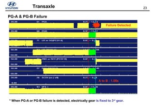
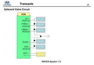
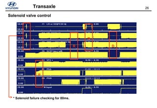
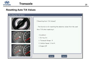
This document provides technical specifications and operating details for various Hyundai transaxle models, including the M5EF2, A4CF0, M5CF1, and A4AF3. It describes the main features of each model such as structure, gear ratios, clutch and brake components. It also provides details on solenoid valve operation for shifting and failure modes which result in the transmission defaulting to 3rd gear. The document aims to communicate the key technical details and functions of Hyundai automatic transaxle systems to transmission engineers.

![2Transaxle
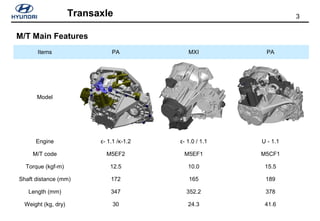
TM Variation
Engine T/M Area
Model
Volume
[cc]
[PS/kg.m] M/T A/T India Europe General
ε-1.1
(G4HG)
1,086 64/9.9
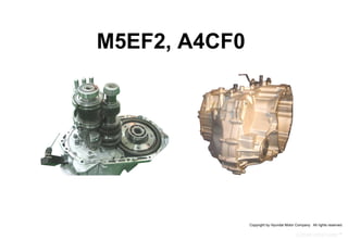
M5EF2 A4CF0
●
(’07.10)
●
(’07.12)
●
(’07.12)
κ-1.2
(G4LA)
*1,248 77/11.8 -
●
(‘08.9)
●
(‘08.10)
1,197 77/11.2
●
(‘08.9)
- -
U-1.1
(U3FA)
1,120 75/15.5 M5CF1 - -
●
(‘07.12)
-
* It is also called referred to as ‘κ-1.25’ to identify with 1,197cc.](https://image.slidesharecdn.com/184608653-02-pa-transaxle-160402002053/85/184608653-02-pa-transaxle-2-320.jpg)