SlideShare a Scribd company logo
1 of 54
Download to read offline
1
AUTOMOBILE ENGINEERING1
Automobile engineering is an applied science that includes elements of Mechanical engineering,
Electrical engineering, Electronic Engineering, Software Engineering and Safety engineering as
applied to the design, manufacture and operation of automobiles, buses and trucks and their
respective engineering subsystems.
The word automobile comes, via the French automobile, from the Ancient Greek word (autos,
"self") and the Latin mobiles ("movable"); meaning a vehicle that moves itself, rather than being
pulled or pushed by a separate animal or another vehicle. The alternative name car is believed to
originate from the Latin word carrus or carrum ("wheeled vehicle)
What is an Automobile?
The automobile is a self propelled vehicle that travels on land. It usually has four wheels. An
engine provides the power to move the vehicle. As the name implies, it is a mobile or moving
power unit on road. Self- propelled means unit which contains its own power source, necessary
for moving, within itself .As a vehicle ,it is used for transportation of passenger and goods.
1.1. INTRODUCTION
Transportation has become unavoidable for the social and economic development of mankind.
Men animals and various goods are transported from one place to another by different modes of
transport.
1. Water transport such as ships, boats, hovercrafts.
2. Air transport such as aeroplanes, helicopters.
3. Space transport such as space crafts.
4. Land transport such as railways, roadways.
Road transport is most popular mode of travelling and transportation and accounts for nearly
70% of all modes of transport available.
Motor vehicle is a self-propelling unit which carries the passengers or goods and ply on the road
surface. The motor vehicle or automobile or auto vehicle is driven by an internal combustion
engine or a prime mover operated by combustion of a fuel or electricity or a battery.
There is a wide range of automobiles designed for specific duty. The two-wheeler mopeds,
scooters, motor-cycle are used by individuals, four-wheeler cars and jeeps are family vehicles,
vans (minibus) and buses serve the society by transporting people, trucks are required for
carrying goods, tractors are field vehicles, bulldozers are used in construction work and gun-
carriage is involved in military operations. The automobile has created a new revolution in the
history of mankind. The modern age is called “auto age” as the impact of the society has been
very profound.
2
1.2. HISTORY OF AUTOMOBILE DEVELOPMENT
The history of automobile development and growth is very fascinating. It runs together with the
history of development of engines. This can studied as under.
1.2.1. European Development
The awn of automobile history dates back to 1770 when a Frenchman, Nicholas Carnot, built the
first road vehicle propelled by its own power. The French artillery officer built a three-wheeler
steam tractor for handling a canon. It could work for 15 minutes only and attained a sped of
about 2.5 mph.
The automobile or the car as we now today evolved from the horse-drawn carriage, and perhaps
the 19th century tricycle; but as the years went by it gradually lost its likeness to any of its
progenitors. The saga of the car really began as recently as 1860, when Jean Etienne Lenoir, a
Belgian inventor, built the first practicable gas engine. Etienne’s engine was fed on a mixture of
coal gas and air and no compression meant that it was not efficient.
The next significant development came in 1876 when Count Nikolous Otto, a German engineer,
successfully applied the four- stroke principle which enabled the charge to be compressed with
significantly better performance. At about the same time petrol came to substitute the coal gas.
During the 1880’s Germany was the hub of automobile development with Gottlieb Daimler and
Carl Benz at the helms of affairs. They were building their cars for sale in 1886. The engine was
placed in the front of the chassis, hooked up to a sliding gear transmission, brake pedal, clutch
and acceleration were incorporated.
By the turn of the century, designers began increasing the number of the cylinder and a prototype
in-line 6-cylinder engine appeared in 1902. The design improvement awakened the public to the
next six years, production and sale of these vehicles became a business.
The early 1920’s saw the beginning of a period of gradual change and refinement in automobile
design. The spark ignition engine was the power plant of motor vehicle and kicked out steam and
electrical rivals. Water-cooled engine were almost certain. The engine were located in the front
of the chassis. The poppet valve was used in every engine design. Major improvements have
been made in every car feature. The main design requirements emphasized on production of
reliable vehicles to function at all times under all condition which would be increasingly
comfortable to ride in and easy to operate.
1.2.2. American Development
When Europe was struggling to make his vehicle run, came the period, in which the development
of mass-production methods permitting lower prices played a dominant role in America. In 1908
Ford started off his Model T with an initial run of 2,000 vehicles, an output unheard of at that
time. Ever since, the correlation of design and production efficiency has influenced the trend of
modern vehicle construction and popularized the use of automobiles. The life of tyres has been
increased, independent front-wheel suspension has been introduced; four-wheel hydraulic brakes
have been incorporated, the higher compression ralios and availability of new materials have
helped to enhance power-weight ratio.
3
Substantial progress has been made after the second world war in every car feature such as
reliability and safety, ease and comfort, economy of operation, pleasing appearance. Safety and
exhaust emission were the additional features. Research and development continue to produce
computer controlled vehicles powered with nuclear engines and fuel cells.
1.2.3. Indian Development
At the end of 1900, the cars arrived in India and were used by Britishers and Kings of states. In
pre-Independent India, cars were imported and it was only in 1946, Hindustan Motors was set up
in Calcutta. It was followed by Premier Automobiles in 1947 to produce cars and Mahindra and
Mahindra in 1949 to produce jeeps in Bombay. Standard Motors was established in Madras in
1950. The industrial giant, Tata introduced a plant for the manufacture was started in India with
foreign collaborations and as such could not contribute much to improve the design and
manufacture of new cars.
The production of all the cars was far below the nation’s demand. Maruti Udyog Limited was
emphasized in 1982 in collaboration with Suzuki of Japan to manufacture small cars. It has
helped to automobiles the country. New models have been introduced by various companies in
recent years which have the latest features and machines available for all income group of the
country’s population.
ENGINES
INTRODUCTION
Heat engines absorb energy in the form of heat and convert part of it into mechanical energy and
deliver it as work, the balance being rejected as heat. These devices derive the heat energy from
the combustion of a fuel. Based on the location of the combustion process, heat engines are
classified into internal combustion and external combustion engines.
Internal combustion engines (IC engines) are those where the combustion of the fuel takes place
inside the engines – eg. automobile engines. In the case of external combustion engines,
combustion of fuel occurs outside the engines and the working gas so heated is then admitted
into the engines for conversion and work extraction – eg. steam generated in a boiler is then
admitted to steam engines for producing work.
Internal combustion Engines
Advantages:-
- Greater thermal efficiency .
- Lower weight to output ratio.
- Lower initial cost.
- Compact and most suitable for portable applications.
- Lesser cooling requirements.
4
Classification of I C Engines:-
i) On the basis of Basic engine design:-
(1) Reciprocating
(2) Rotary (Wankel)
(ii) On the basis of Working cycle:-
(1) Otto cycle (SI Engine)
(2) Diesel cycle (C I Engine)
(iii) On the basis of Strokes:-
(1) Four stroke Engine
(2) Two stroke Engine
(iv) On the basis of Fuel:-
(1) Petrol
(2) Diesel, CNG& LPG
(v) On the basis of Fuel supply:-
(1) Carbureted types
(2) Injection types
(vi) On the basis of Ignition:-
(1) Battery ignition
(2) Magneto ignition
(vii) On the basis of Cooling Method:-
(1) Water cooled
(2) Air cooled
(viii) On the basis of cylinder arrangement:-
(1) In line Engine
(2) V Engine
(3) Radial Engine etc.
(ix) On the basis of valve location:-
(1) Overhead valve
(2) Side valve
(x) On the basis of Application:-
(1) Automobile engines
(2) Marine engines
(3) Aircraft engines
5
(4) Industrial engines
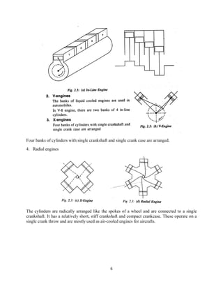
1. In-line engines
The cylinders are attached to the same crank case, one cylinder behind the other with their axes
parallel. These cylinders may be vertical, horizontal or inverted. 4-6 water cooled cylinders
arranged in-line are very popular in automobiles.
6
Four banks of cylinders with single crankshaft and single crank case are arranged.
4. Radial engines
The cylinders are radically arranged like the spokes of a wheel and are connected to a single
crankshaft. It has a relatively short, stiff crankshaft and compact crankcase. These operate on a
single crank throw and are mostly used as air-cooled engines for aircrafts.
7
8
9
Parts of an IC engine
The main components of a standard IC engine are briefly described below:
1. Cylinder head.
• It is attached to the top surface of the cylinder block
• gaskets are used to provide a tight leak proof joint at the interface of the head and the
block
• the cylinder head forms a combustion chamber above each cylinder.
10
• It also contains valve guides, valve seats, coolant jackets and threaded holes for spark
plugs or injection
• materials used- gray cast iron or aluminium alloys
2. Cylinder block
• The basic framework of the engine
• It houses the engine cylinders
• There are passages for the circulation of coolant
• carries lubrication oil to various components through drilled passages
• It support and encloses the moving parts
• All static & dynamic loads, unbalanced forces and torsional vibrations are transmitted to
frame through this block
• It subjected to extreme temp: gradient
• Materials used- gray cast iron & Aluminium alloys
3. Piston.
The functions
1. transmit the force of explosion to the crankshaft.
2. form a seal so that the high pressure gases in the combustion chamber do not escape into the
crankcase.
3. serve as a guide and a bearing for small end of the connecting rod.
desirable characteristics
Silent in operation
Seizure does not occur
Sufficient resistance to corrosion
Lighter in weight
Materials for piston
1. Aluminium
cast iron
11
4. Connecting rod.
• it is the connection between the piston and crank shaft
• Its function is to convert the reciprocating motion of the piston into the rotary motion of
the crankshaft.
• two rod-ends, called the small end and the big end.
• The small end of the rod is connected to the piston pin.
• The big end connected to the crankpin
• It usually has “ I ” beam cross section
• It is made of forged steel
5. Crankshaft.
• Crankshaft is the engine component from which the power is taken.
• It is the part on to which the reciprocating motion is converted into rotating motion
• It receives the power from the connecting rods in the designated sequence
6. Crank case
• base of the engine
• supports the crank shaft and engine
• attached to the bottom face of the cylinder block
12
• The oil pan and the bottom part of the cylinder block together are called crank case
• Material used-aluminium alloys
• It provide the support for the main journals and bearings
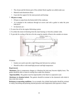
7 Oil pan or sump
• Oil pan or sump forms the bottom half of the crankcase.
• It is attached to the crankcase through set screws and with a gasket to make the joint
leak-proof.
• Its functions are :
I. To store the oil for the engine lubricating system.
2. To collect the return oil draining from the main bearings or from the cylinder walls.
3. To provide for cooling of the hot oil in the sump by transfer of heat to the outsider air stream
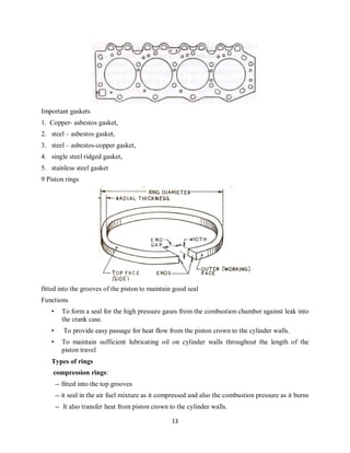
8 Gaskets
• Gaskets are used to provide a tight fitting joint between two surfaces
• Should be able to with stand high pressure and high temperature
Requirements
Resistance. Due to temperature changes or vibrations the joint may become slightly loose. The
gasket should be able to retain its sealing force under this situation.
Impermeability. The gaskets must be impermeable to the fluid it is expected to seal.
Resistance to chemical attack. The gaskets should be resistant to the chemicals with which it
may come into contact
Resistance to operating conditions. As an example, the cylinder head gasket should be resistant
to widely fluctuating and pulsating internal pressures and temperatures and exposure to flame
13
Important gaskets
1. Copper- asbestos gasket,
2. steel – asbestos gasket,
3. steel – asbestos-copper gasket,
4. single steel ridged gasket,
5. stainless steel gasket
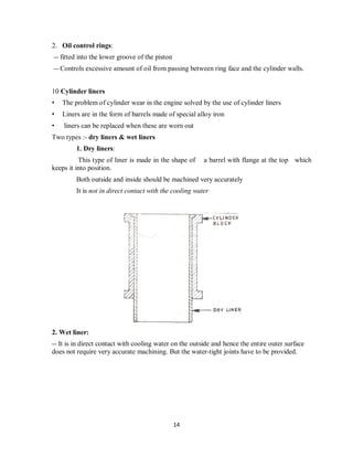
9 Piston rings
fitted into the grooves of the piston to maintain good seal
Functions
• To form a seal for the high pressure gases from the combustion chamber against leak into
the crank case.
• To provide easy passage for heat flow from the piston crown to the cylinder walls.
• To maintain sufficient lubricating oil on cylinder walls throughout the length of the
piston travel
Types of rings
compression rings:
-- fitted into the top grooves
-- it seal in the air fuel mixture as it compressed and also the combustion pressure as it burns
-- It also transfer heat from piston crown to the cylinder walls.
14
2. Oil control rings:
-- fitted into the lower groove of the piston
-- Controls excessive amount of oil from passing between ring face and the cylinder walls.
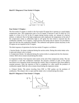
10 Cylinder liners
• The problem of cylinder wear in the engine solved by the use of cylinder liners
• Liners are in the form of barrels made of special alloy iron
• liners can be replaced when these are worn out
Two types :- dry liners & wet liners
1. Dry liners:
This type of liner is made in the shape of a barrel with flange at the top which
keeps it into position.
Both outside and inside should be machined very accurately
It is not in direct contact with the cooling water
2. Wet liner:
-- It is in direct contact with cooling water on the outside and hence the entire outer surface
does not require very accurate machining. But the water-tight joints have to be provided.
15
11 Camshaft
• Carries cams for - each valve and for the operation of fuel pump & ignition system
• It is driven by the crank shaft at half of its own speed
• Cam is a rotating member which imparts reciprocating motion to follower at right angles
to the cam axis.
• The camshaft controlling the opening and closing intervals of the inlet and exhaust valve
• Camshaft consist of a number of cams at suitable angular positions for operating the
valves.
12 Flywheel
• The purpose of the flywheel is to store up energy
• mounted on the crank shaft
• Stores excess energy during the power stroke and returns that energy during other strokes
& maintains const O/p torque
• The size of the flywheel varies with the number of cylinders and general construction of
the engine.
16
Nomenclature of I C Engines
1) Cylinder bore (D):- The nominal inner diameter of the working cylinder.
2) Piston area (A):- Cross sectional area of the piston. This is equal to cylinder bore area
3) Stroke (L):- The nominal distance between TDC & BDC
4) Dead Center: - End points of the strokes
(i) Top dead center (TDC):- Farthest position of piston from crank shaft. It is also called,
Inner Dead Center (IDC)
(ii) Bottom Dead Center (BDC):- Nearest position of piston form crank shaft. It is also called
Outer Dead Center (ODC)
5) Swept Volume (Vs) :- The nominal volume generated by the piston when travelling from one
dead center to next. i.e., TDC to BDC ,
Vs = A×L
6) Clearance Volume (Vc):- The nominal volume or volume for combustion, which is just
above the TDC.
7) Cylinder Volume (V) :- The sum of swept volume and clearance volume.
V = Vs + Vc
8) Compression ratio (r) :- Ratio of cylinder volume to clearance volume;
V
r
Vc
=
Four Stroke I C Engines
In a four-stroke engine, the cycle of operations is completed in four strokes of the piston or two
revolutions of the crankshaft. During the four strokes, there are five events to be Completed, viz.,
suction, compression, combustion, expansion and exhaust. Each stroke consists of 180° of
17
crankshaft rotation and hence a four-stroke cycle is completed through 720° of crank rotation.
The cycle of operation for an ideal four-stroke SI engine consists of the following four strokes:
1. Suction Stroke (0 -180°)
2. Compression Stroke (180°-360°)
3. Expansion Stroke (360°-540°)
4. Exhaust Stroke (540°-720°)
Working principle of a Four Stroke SI Engine
Suction or Intake Stroke: Suction stroke starts when the piston is at the top dead centre and
about to move downwards. The inlet valve is open at this time and the exhaust valve is closed.
Due to the suction created by the motion of the piston towards the bottom dead centre, the charge
consisting of fuel-air mixture is drawn into the cylinder. When the piston reaches the bottom
dead centre the suction stroke ends and the inlet valve closes. The charge taken into the cylinder
during the suction stroke is compressed by the return stroke of the piston. During this stroke both
inlet and exhaust valves are in closed position. The mixture that fills the entire cylinder volume
is now compressed into the clearance volume. At the end of the compression stroke the mixture
is ignited with the help of a spark plug located on the cylinder head. In ideal engines it is
assumed that burning takes place instantaneously when the piston is at the top dead centre and
hence the burning process can be approximated as heat addition at constant volume. During the
burning process the chemical energy of the fuel is converted into heat energy producing a
temperature rise of about 2000 °C
The pressure at the end of the combustion process is considerably increased due to the heat
release from the fuel. At the end of the expansion stroke the exhaust valve opens and the inlet
valve remains closed. The pressure falls to atmospheric level a part of the burnt gases escape.
The piston starts moving from the bottom dead centre to top dead centre and sweeps the burnt
gases out from the cylinder almost at atmospheric pressure. The exhaust valve closes when the
piston reaches T DC. At the end of the exhaust stroke and some residual gases trapped in the
clearance volume remain in the cylinder. These residual gases mix with the fresh charge coming
in during the following cycle, forming its working fluid. Each cylinder of a four stroke engine
completes the above four operations in two engine revolutions, one revolution of the crankshaft
occurs during the suction and compression strokes and the second revolution during the power
and exhaust strokes. Thus for one complete cycle there is only one power stroke while the
crankshaft turns by two revolutions. For getting higher output from the engine the heat release
should be as high as possible and the heat rejection should be as small as possible.
18
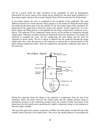
Ideal P-V Diagram of Four Stroke S I Engine
Four Stroke C I Engine:-
The four-stroke CI engine is similar to the four-stroke SI engine but it operates at a much higher
compression ratio. The compression ratio of an SI engine is between 6 and 10 while for a CI
engine it is from 16 to 20. In the CI engine during suction stroke, air, instead of a fuel-air
mixture, is inducted. Due to the high compression ratio employed, the temperature at the end of
the compression stroke is sufficiently high to self ignite the fuel which is injected into the
combustion chamber. In CI engines, a high pressure fuel pump and an injector are provided to
inject the fuel into the combustion chamber. The carburetor and ignition system necessary in the
SI engine are not required in the CI engine.
The ideal sequence of operations for the four-stroke CI engine is as follows:
i. Suction Stroke: Air alone is inducted during the suction stroke. During this stroke intake valve
is open and exhaust valve is closed.
ii. Compression Stroke: Air inducted during the suction stroke is compressed into the clearance
volume. Both valves remain closed during this stroke.
iii. Expansion Stroke: Fuel injection starts nearly at the end of the compression stroke. The rate
of injection is such that combustion maintains the pressure constant in spite of the piston
movement on its expansion stroke increasing the volume. Heat is assumed to have been added at
constant pressure. After the injection of fuel is completed (i.e. after cutoff) the products of
combustion expand. Both the valves remain closed during the expansion stroke.
iv. Exhaust Stroke: The piston traveling from EDC to TDC pushes out the products of
combustion. The exhaust valve is open and the intake valve is closed during this stroke.
Ideal P-V Diagram of Four Stroke C I Engine
19
Comparison of S I and C I Engine
1. Basis of Cycle Otto Cycle
Constant Volume heat addition
Diesel Cycle
Constant pressure heat
addition
2. Fuel highly volatile non-volatile
3. Introduction of
fuel
air + fuel introduced into the
cylinder
only air introduced into the
cylinder
4. Ignition Spark plug Self ignition due to high
temperature
5. Compression
ratio
6 - 10
Bikes ,cars
16 - 20
Diesel cars & trucks
6.Speed Due to light weight, they are high
speed engine
low speed engines
7. ηth Because of lower CR ηth is lower
th r 1
1
r −
η =
ηth is higher or
( )
c
r 1
c
r 11
1
r r 1r −
 −
−  
−  
8. Weight lower peak pressure, engines are
lighter
Heavier
Actual indicating diagram of S I Engine
Two-stroke Engine
As already mentioned, if the two unproductive strokes, viz., the suction and exhaust could be
served by an alternative arrangement, especially without the movement of the piston then there
20
will be a power stroke for each revolution of the crankshaft. In such an arrangement,
theoretically the power output of the engine can be doubled for the same speed compared to a
four-stroke engine. Based on this concept, Dugald Clark (1878) invented the two-stroke engine.
In two-stroke engines the cycle is completed in one revolution of the crankshaft. The main
difference between two-stroke and four stroke engines is in the method of filling the fresh charge
and removing the burnt gases from the cylinder. In the four-stroke engine these operations are
performed by the engine piston during the suction and exhaust” strokes respectively. In a two-
stroke engine, the filling process is accomplished by the charge compressed in crankcase or by a
blower. The induction of the compressed charge moves out the product of combustion through
exhaust ports. Therefore, no piston strokes are required for these two operations. Two strokes are
sufficient to complete the cycle, one for compressing the fresh charge and the other for
expansion or power stroke. The air or charge is inducted into the crankcase through the spring
loaded inlet valve when the pressure in the crankcase is reduced due to upward motion of the
piston during compression stroke. After the compression and ignition, expansion takes place in
the usual way.
During the expansion stroke the charge in the crankcase is compressed. Near the end of the
expansion stroke, the piston uncovers the exhaust ports and the cylinder pressure drops to
atmospheric pressure as the combustion products leave the cylinder. Further movement of the
piston uncovers the transfer ports, permitting the slightly compressed charge in the crankcase to
enter the engine cylinder.
The top of the piston has usually a projection to deflect the fresh charge towards the top of the
cylinder before flowing to the exhaust ports. This serves the double purpose of scavenging the
21
upper part of the cylinder of the combustion products and preventing the fresh charge from
flowing directly to the exhaust ports.
Advantages of two-stroke engines
1. A two-stroke engine has a power stroke every revolution of the crankshaft. Therefore its
power to weight ratio is higher than that of a four-stroke engine.
2. The torque is more uniform in a two-stroke engine, hence it requires a lighter flywheel
than that for a four-stroke engine.
3. Two-stroke engines are simpler in construction than four-stroke engines due to the
absence of valves and their operating mechanism.
4. The friction loss is less in two-stroke engines, therefore it gives higher mechanical
efficiency than four-stroke engines.
5. The capital cost of two-stroke engines is less than that of four-stroke engines.
6. The starting of two-stroke engines is easier than starting of four-stroke engines.
Disadvantages of two-stroke engines
1. The overall efficiency is less than that of four-stroke engines due to (i) inadequate
scavenging as some combustion products are left in the cylinder (ii) loss of fresh charge
during scavenging, and (iii) less effective compression ratio for same stroke long.
2. The engine is always overheated due to power stroke in every revolution.
3. The consumption of lubricating oil is higher as it is subjected to higher temperatures.
4. The exhaust of two-stroke engines is noisier needing more baffling in the silencers.
Parts
Cylinders → cast iron, alloy steel
Cylinder head → cast iron, aluminium alloy
Piston → cast iron, aluminium alloy
Piston rings → silicon, cast iron
Judger pin → steel
Valves → specially alloy steels
Connecting rod → steel
Crank shaft → alloy steel
Crank case → steel, cast iron
Cylinder timer → nickel alloy steel, cast iron
Bearing → white metal
22
Comparison of Four stroke and two stroke cycle engines
1. The cycle is completed in Four stroke
of the piston or two revolutions. i.e., one
power stroke is obtained in every two
revolutions.
2. Turning moment is not so uniform and
hence heavier flywheel is needed.
3. Power produced for same size of
engine is small.
4. Four stroke engine contains valves and
valve mechanisms.
5. Heavy weight and complication of
valve mechanism.
6. Volumetric efficiency more due to
greater time of induction. (one stroke for
suction stroke)
7. Thermal efficiency high.
8. Cars, buses, trucks, industries etc.
1. The cycle is completed in two-strokes
of the piston or in one revolution of
crankshaft. i.e., one power stroke is
obtained in one revolution of crank shaft.
2. More uniform turning movements and
hence lighter flywheel is needed.
3. Power produced for same size of
engine is more (theoriticaly twice,
actually about 1.3 times)
4. No valves but only ports.
5. Light weight and simplicity due to the
absence of valve mechanism.
6. Less volumetric efficiency due to
lesser time for induction.
7. Thermal efficiency lower
8. Compact
scooters, bikes etc (petrol)
Two-stroke diesel engines used in very
large sizes, more than 60 cm base. (ship)
because low weight and compactness.
eg:- Marine Engine, Fork lift etc.
WANKEL ENGINE
Dr. Felix Wankel was the founder of the first successful rotary engine. He was invented in 1957.
The engine has a three lobe rotor which is driven eccentrically in a casing in such a way that
there are thrice separate volumes trapped between the rotor and the casing. These three volumes
perform induction, compression, combustion, expansion and exhaust process in sequence.
Sealing, seal wear ad heat transfer were some of the development problems of Wankel engines.
The reciprocating piston has been replaced by a triangular-shaped rotor. With on complete
revolution of the rotor the power pulses will occur. There are three complete four-stroke cycles
(revolutions of a rotor). The gear ratios are such that the output shaft rotates at three times the
speed of rotor.
23
-Passenger cars are manufactured by Mazda, Japan & Rolls Royees Ltd.
- Compression ratio is 18.
Advantages:-
(1) Power output/weight ratio is higher because of its compactness.
(2) Simple in design - no valve problems.
(3) No. of parts is much less than a conventional four stroke S I engine. Therefore it is less
costly.
(4) Mechanical efficiency is better because of lower frictional losses.
Disadvantages:-
(1) The engine has lower efficiency because higher heat transfer rate.
(2) Exhaust emissions are higher because of poor combustion chamber shape.
(3) There may be starting trouble.
(4) Efficient operation of the engine requires efficient seal between two sides of the rotor and its
casing.
(5) The spark plug life is short without effective cooling.
CARBURETION
In the SI engine a combustible fuel-air mixture is prepared outside the engine cylinder. The
process of preparing this mixture is called “carburetion”. The carburetor is a device which
atomizes the fuel and mixes it with air and is most important part of the induction system. The
pipe that carries the prepared mixture to the engine cylinder is called the intake manifold.
During suction stroke vacuum is created in the cylinder which causes the air to flow through the
carburetor and the fuel to be sprayed form the fuel jets. Because of the volatility of the fuel, most
of the fuel vaporizes and forms a combustible fuel-air mixture. However, some of the larger
droplets may reach the cylinder in the liquid form and must be vaporized and mixed with air
24
during the compression stroke before ignition by the electric spark.
Four important factors which significantly affect the process of combustion are:
1. The time available for the preparation of the mixture.
2. The temperature of the incoming air of the intake manifold.
3. The quality of the fuel supplied.
4. The design of the induction system and combustion chamber.
Properties of the air-fuel mixtures
Range of air-fuel ratios = 7: 1 to 20 : 1
(1) Mixture requirement for maximum power
- Maximum power is obtained at about 12.5: 1 A/F
- Maximum energy is released when slightly excess fuel is introduced so that the oxygen present
in t he cylinder is utilized.
Disadvantage is partial combustion & less energy release.
(2) Mixture requirement for maximum specific fuel consumption
- Maximum efficiency occurs at as A/C of about 17:1
-Maximum efficiency occurs at a point slightly leaves than the chemically correct A/F ratio
because excess air requires complete combustion of fuel when mixing is not perfect.
A/P ratio (mass) Designation Power output Specific fuel consumption
18 - 22
16 - 18
15 approx.
12 - 14
Very weak
Weak
Chemically correct
Rich
Very Rich
40 % less
10% less
4% less
Max. Power
20 % less
Low
Maximum (economical)
4% more
25 - 30% more
35% - 50% more
25
A SIMPLE CARBURETOR
It consists of a float chamber nozzle with metering orifice, venturi and throttle valve. The float
and a needle valve system maintain a constant height of petrol in the float chamber.
During suction stroke air is drawn through the venturi .The air passing through the venturi
increases in velocity and the pressure in the venturi threat decreases. From the float chamber, the
fuel is fed to a discharge jet, the tip of which is located in the throat of the venturi. Now because
the pressure in the float chamber is atmospheric and that at the discharge jet below atmospheric a
pressure differential, called “carburetor depression, exists between them. This causes discharge
of fuel into the air stream and the rate of flow is controlled or metered by the size of smaller
section in the fuel depression is 4 - 5cm below atmospheric.”
Essential Parts of a Carburetor
A carburetor consists essentially of the following parts, viz.
i. Fuel strainer
ii. Float chamber
26
iii. Main fuel metering and idling nozzles
iv. Choke and throttle
The various parts mentioned above are discussed briefly in the following section.
The Fuel Strainer
As the gasoline has to pass through a narrow nozzle exit there is every possibility that the nozzle
may get clogged during prolonged operation of the engine. To prevent possible blockage of the
nozzle by dust particles, the gasoline is filtered by installing a fuel strainer at the inlet to the float
chamber. The strainer consists of a fine wire mesh or other type of filtering device, cone shaped
or cylindrical shaped.
The Float Chamber
The function of a float chamber in a carburetor is to supply the fuel to the nozzle at a
constant pressure head. This is possible by maintaining a constant level of the fuel in the float
bowl. The float in a carburetor is designed to control the level of fuel in the float chamber. This
fuel level must be maintained slightly below the discharge nozzle outlet holes in order to provide
the correct amount of fuel flow and to prevent leakage of fuel from the nozzle when the engine is
not operating. When the float rises with the fuel coming in, the fuel supply valve closes and stops
the flow of fuel into the chamber.
The Main Metering and Idling System
The main metering system of the carburetor controls the fuel feed for cruising and full
throttle operations (Fig.16.l0). It consists of three principal units:
i. The fuel metering orifice through which fuel is drawn from the float chamber
ii. The main discharge nozzle
iii. The passage leading to the idling system
The three functions of the main metering system are
i. To proportion the fuel-air mixture
ii. To decrease the pressure at the discharge nozzle exit
iii. To limit the air flow at full throttle
The automobiles fitted with SI engine require a rich mixture for idling and low speed operation.
Usually air-fuel ratio of about 12:1 is required for idling. In order to provide such rich mixture,
during idling, most of the modern carburetors incorporate special idling system is their
construction. This system gets operational at starting, idling and very low speed running of the
vehicle engine and is non operational when throttle is opened beyond 15% to 20%.
27
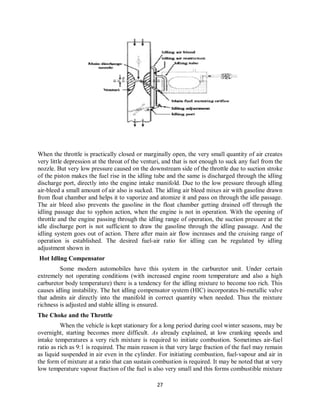
When the throttle is practically closed or marginally open, the very small quantity of air creates
very little depression at the throat of the venturi, and that is not enough to suck any fuel from the
nozzle. But very low pressure caused on the downstream side of the throttle due to suction stroke
of the piston makes the fuel rise in the idling tube and the same is discharged through the idling
discharge port, directly into the engine intake manifold. Due to the low pressure through idling
air-bleed a small amount of air also is sucked. The idling air bleed mixes air with gasoline drawn
from float chamber and helps it to vaporize and atomize it and pass on through the idle passage.
The air bleed also prevents the gasoline in the float chamber getting drained off through the
idling passage due to syphon action, when the engine is not in operation. With the opening of
throttle and the engine passing through the idling range of operation, the suction pressure at the
idle discharge port is not sufficient to draw the gasoline through the idling passage. And the
idling system goes out of action. There after main air flow increases and the cruising range of
operation is established. The desired fuel-air ratio for idling can be regulated by idling
adjustment shown in
Hot Idling Compensator
Some modern automobiles have this system in the carburetor unit. Under certain
extremely not operating conditions (with increased engine room temperature and also a high
carburetor body temperature) there is a tendency for the idling mixture to become too rich. This
causes idling instability. The hot idling compensator system (HIC) incorporates bi-metallic valve
that admits air directly into the manifold in correct quantity when needed. Thus the mixture
richness is adjusted and stable idling is ensured.
The Choke and the Throttle
When the vehicle is kept stationary for a long period during cool winter seasons, may be
overnight, starting becomes more difficult. As already explained, at low cranking speeds and
intake temperatures a very rich mixture is required to initiate combustion. Sometimes air-fuel
ratio as rich as 9:1 is required. The main reason is that very large fraction of the fuel may remain
as liquid suspended in air even in the cylinder. For initiating combustion, fuel-vapour and air in
the form of mixture at a ratio that can sustain combustion is required. It may be noted that at very
low temperature vapour fraction of the fuel is also very small and this forms combustible mixture
28
to initiate combustion. Hence, a very rich mixture must be supplied. The most popular method of
providing such mixture is by the use of choke valve. This is simple butterfly valve located
between the entrance to the carburetor and the venture throat .When the choke is partly closed,
large pressure drop occurs at the venturi throat that would normally result from the quantity of
air passing through the venturi throat. The very large depression at the throat inducts large
amount of fuel from the main nozzle and provides a very rich mixture so that the ratio of the
evaporated fuel to air in the cylinder is within the combustible limits. Sometimes, the choke
valves are spring loaded to ensure that large carburetor depression and excessive choking does
not persist after the engine has started, and reached a desired speed. This choke can be made to
operate automatically by means of a thermostat so that the choke is closed when engine is cold
and goes out of operation when engine warms up after starting.
The speed and the output of an engine is controlled by the use of the throttle valve,
which is located on the downstream side of the venturi. The more the throttle is closed the
greater is the obstruction to the flow of the mixture placed in the passage and the less is the
quantity of mixture delivered to .the cylinders. The decreased quantity of mixture gives a less
powerful impulse to the pistons and the output of the engine is reduced accordingly. As the
throttle is opened the output of the engine increases. Opening the throttle usually increases the
speed of the engine. But this is not always the case as the load on the engine is also a factor. For
example, opening the throttle when the motor vehicle is starting to climb a hill mayor may not
increase the vehicle speed, depending upon the steepness of the hill and the extent of throttle
opening. In short, the throttle is simply a means to regulate the output of the engine by varying
the quantity of charge going into the cylinder.
The choke and the throttle
Types of Carburetors
(1) Updraught type: - in which the air enters at the bottom and leaves at the top. So that the
direction of its flow is upwards. The disadvantages of the updraught carburettor are that it
must left the sprayed fuel droplet by air friction. Hence it must be designed to relatively
small mixing tube and throat so that even at low engine speeds the air velocity is
sufficient to left and carry the fuel particle along. Otherwise, the fuel droplets tend to
29
separate out.
(2) Down draught Carburetor: - consists of a horizontal mixing tube with a float chamber on
one side of it. By using a cross-draught carburetor in engines, one-right angled turn in the
inlet passage is eliminated and the resistance to flow is reduced.
(3) Constant choke Carburetor:- the air and fuel flow areas are always constant. But the pressure
difference or depression which causes the flow of fuel and air. eg. Solex and Zenith Carburetors.
(4) Constant Vacuum Carburetor:-variable chock carburetor - air and fuel flow areas are being
varied as per the demand on the engine, while the vacuum is maintained to be always same. eg. S
U and Carter carburetor.
Multiple Venturi Carburettor
Multiple Venturi system uses double or triple venturi. The boost venturi is located concentrically
within the main venturis. The discharge edge of the boost venturi is located at the throat of the
main venturi. The boost venturi is positioned up stream of the throat of the layer through the
boost venturi. Now the pressure at the boost venturi exit equals the pressure at the main venturi
throat. The fuel nozzle is located at the throat of the boost venturi.
- high depression is created in the region of the fuel nozzle.
- improved atomization are possible
- better control
30
Multi Jet & Multi based Ventur’s carburetor
Advantage
1. Duel carburetor supplies a charge of the mixture to the cylinder which is uniform in quality.
2. Distribution is better
COOLING SYSTEMS OF IC ENGINES
We know that in case of Internal Combustion engines, combustion of air and fuel takes place
inside the engine cylinder and hot gases are generated. The temperature of gases will be around
2300-2500°C. This is a very high temperature and may result into burning of oil film between
the moving parts and may result into seizing or welding of the same. So, this temperature must
be reduced to about 150-200°C at which the engine will work most efficiently. Too much
cooling is also not desirable since it reduces the thermal efficiency. So, the object of cooling
system is to keep the engine running at its most efficient operating temperature. It is to be noted
that the engine is quite inefficient when it is cold and hence the cooling system is designed in
such a way that it prevents cooling when the engine is warming up and till it attains to maximum
efficient operating temperature, then it starts cooling
Necessity for engine cooling
• Engine valves warp (twist) due to over heating.
• Damage to the materials of cylinder body and piston.
• Lubricating oil decomposes to form gummy and carbon particles.
• Thermal stresses are set up in the engine parts and causes distortion (twist or change
shape) and cracking of components.
• Pre-ignition occurs (i.e. ignition occurs before it is required to igniter) due to the
overheating of spark plug.
• Reduces the strength of the materials used for piston and piston rings.
• Overheating also reduces the volumetric efficiency
Methods of cooling
1 Air cooling 2 Water cooling
31
1AIR COOLING
Advantages of Air Cooled System
Following are the advantages of air cooled system :
(a) Radiator/pump is absent hence the system is light.
(b) In case of water cooling system there are leakages, but in this case there are no leakages.
(c) Coolant and antifreeze solutions are not required.
(d) This system can be used in cold climates, where if water is used it may freeze.
Disadvantages of Air Cooled System
Can applied only for small and medium sized engines
• Air cooling is not as effective as water cooling and efficiency of the engine is reduced.
• Engine parts are not uniformly cooled.
(The front portion of the engine which faces the air is cooled more than the rear portion. )
32
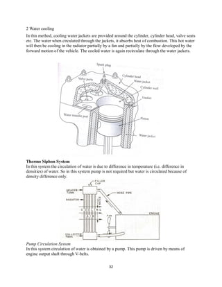
2 Water cooling
In this method, cooling water jackets are provided around the cylinder, cylinder head, valve seats
etc. The water when circulated through the jackets, it absorbs heat of combustion. This hot water
will then be cooling in the radiator partially by a fan and partially by the flow developed by the
forward motion of the vehicle. The cooled water is again recirculate through the water jackets.
Thermo Siphon System
In this system the circulation of water is due to difference in temperature (i.e. difference in
densities) of water. So in this system pump is not required but water is circulated because of
density difference only.
Pump Circulation System
In this system circulation of water is obtained by a pump. This pump is driven by means of
engine output shaft through V-belts.
33
Radiator
It mainly consists of an upper tank and lower tank and between them is a core. The
upper tank is connected to the water outlets from the engines jackets by a hose pipe and the lover
tank is connect to the jacket inlet through water pump by means of hose pipes.
There are 2-types of cores :
(a) Tubular
(b) Cellular as shown.
When the water is flowing down through the radiator core, it is cooled partially by the fan which
blows air and partially by the air flow developed by the forward motion of the vehicle. As shown
through water passages and air passages, wafer and air will be flowing for cooling purpose. It is
to be noted that radiators are generally made out of copper and brass and their joints are made by
soldering.
34
Thermostat Valve
It is a valve which prevents flow of water from the engine to radiator, so that engine readily
reaches to its maximum efficient operating temperature. After attaining maximum efficient
operating temperature, it automatically begins functioning. Generally, it prevents the water
below 70°C.
Figure 5.7 shows the Bellow type thermostat valve which is generally used. It contains a bronze
bellow containing liquid alcohol. Bellow is connected to the butterfly valve disc through the link.
When the temperature of water increases, the liquid alcohol evaporates and the bellow expands
and in turn opens the butterfly valve, and allows hot water to the radiator, where it is cooled.
35
• .
•
Advantages of water cooling Disadvantages of water cooling
• Can applied for large sized engines • More weight & high cost, since it uses radiator,
pump, fan etc.
• Cooling is more efficient, thus engine
efficiency is more.
• Requires more maintenance.
(The engine may have to be stopped even if a small
leakage of water is detected in the radiator.)
• Uniform cooling is obtained. • Cooling system failure may cause the engine
damage
• Water cooled engines can be installed
anywhere.
• In cold weather, freezing of water causes trouble.
(An electric heater may be required to heat the
radiator.)
• Smaller frontal area is possible • Water circulating pump consumes more power.
• Less chances of engine overheating . Water causes scale formation in the water circulating
jacket and corrosion of materials, hence greater
maintenance is required.
Engine temperature can be controlled
Over-cooling of the engine results in
• insufficient vaporization of fuel,
• starting troubles,
• high fuel consumption,
• higher emissions,
• loss of power,
• lower thermal efficiency
Lubrication Systems
The functions of lubricating oils are:
1. Remove the heat from the mating parts.
2. Reduce the friction between moving parts
3. Acts as a sealing agent between piston rings and cylinder to prevent the leakage of
working gases.
4. Clean the metal parts.
5. Reduction of noise
36
Types of lubricating systems:
1 Mist lubrication system (petroil system)
2 Wet Sump lubrication system
(a)Splash Lubrication system
(b)Splash and pressure lubrication system
(c)Pressurized lubrication system
3 Dry Sump lubrication system
PETROIL (OR) MIST LUBRICATION
This type of lubrication is used for two stroke cycle engines. The lubrications oil (2 to 3 percent)
is mixed with petrol in the fuel tank. The oil and fuel mixture is inducted through the carburettor.
Petrol gets evaporated and the oil lubricates the main parts of the cylinder.
The fuel -oil ratio used is important for good performance. the optimum fuel -oil ratio used is
50:1.
ADVANTAGE
• Separate lubricating system is not needed.
• No maintenance cost for lubriction system.
• Weight of engine is reduced by avoiding separate lubricating system.
DISADVENTAGE
• If oil is less there is chance for seizure of engine.
• More oil makes excess smoke in the exhaust.
• chance of corrosion of bearing surfaces (acidic vapour)
• need thorough mixing for effective lubrication
• Spark plug fouling
• Rings sticking
• combustion chamber deposits
2.WET SUMP LUBRICATION
In this system a big oil sump is provided at the base of crank case.From the sump the oil is
pumped to different parts of the engine.The main types of wet sump lubrication system are
1. splash lubrication system.
2. Pressure lubricatio system.
a) SPLASH LUBRICATION SYSTEM
37
The simple sketch of splash lubriction system is shown lubricating oil is filled in the sump.
scoop are attached to the big end of connecting rod. When every time the piston reaches bottom
dead center (BDC) the scoop dip into the sump and carries the lubricating oil . The lubricating oil
is splashed to the piston, cylinder , small & big end of connecting rod, main bearing and can
shaft bearing. The splashed oil settle on the engine parts and then falls into the sump.
It is a Simplest method of lubrication. And Suitable only for small capacity engines.
b)PRESSURE LUBRICATION SYSTEM
In this system lubrication oil is applied to the engine parts under pressure using a pressure pump .
the simple diagram of pressure lubrication system is shown
The oil pump is submerged in the sump . the oil from the sump is delivered to the oil filter . The
pressure of oil is increased by the punp. The oil is forced under pressure to different parts of
engine through oil tubes (or) oil holes. Seperate oil tubes carry oil to the bearing.
From the bearing oil floats to the connecting rod through the oil hole between the connecting rod
and crank shaft.
Then this oil flows to the piston pin though oil hole and sprayed over the piston ,piston rings,
cylinder valves and other engine parts.
38
Dry Sump Lubrication
In this type, supply of fuel is carried from an external tank.An oil pump draws oil from
the supply tank and circulates it under pressure to the various bearings of the engine. Oil
dripping from the cylinders and bearings is removed by scavenging pump which in turn is
fed back to the supply tank after filtering. A cooler is provided in the dry sump to
remove heat from the oil.
39
INJECTION SYSTEMS
Functional requirements of an injection system
(1) Accurate metering of the fuel injected/cycle. The quantity of the fuel metered should vary to
meet changing speed and load requirements.
(2) Timing of the fuel injection in the cycle.
(3) Proper control of rate of injection.
(4) Proper atomization of fuel into very fine droplets.
(5) Uniform distribution of fuel droplets through out the combustion chamber.
(6) To supply equal quantities of mixed fuel to all cylinders in case of multi cylinder engines.
Injection in SI Engine
Advantages Injection in SI Engine
-- very high quality fuel distribution
-- restrictions in the passage is removed
-- fuel consumption is less
-- response of the engine to the throttle control is rapid
-- Need very small time for transportation of mixture
-- Fuel injection equipment is more precise
Disadvantages Injection in SI Engine
-- initial cost is very high
--relatively much complicated mechanisms
-- increased maintenance required
-- very careful filtration of fuel is required
-- more mechanical and electrical components
SI Engine injection Types
1. Gasoline Direct Injection (GDI)--Direct injection of fuel into cylinder
2. Throttle body injection (SPFI) -- injection of fuel into the inlet manifold
3. Port injection (MPFI)-- injection of fuel close to the inlet valve
40
Single Point Fuel Injection(SPFI) or Throttle body injection
41
Multi Point Fuel Injection (MPFI) or Port Injection
-- technology used in petrol engines
-- use of modern computer system (ECU). i.e. intelligent way of controlling the engine
-- improve power, fuel economy, efficiency and other performances and reduce harmful
emissions, noise, vibrations
-- in MPFI, each cylinder has one injector which is controlled by ECU
-- timing and amount of fuel injection are controlled by ECU
-- ECU works with input signals from multiple sensors
-- timing and amount of fuel injection based on these signals
-- in MPFI, each cylinder is treated independently
Advantages of MPFI
• improve power and torque
• Improve performance
• Improve efficiency
• Improve fuel economy
• reduce noise and vibrations
• reduce emissions
• Superior pick up
• It helps to overcomes the difficulty in cold starting
Disadvantages of MPFI
• Initial cost high
• Costly spare parts
• More maintenances
• High maintenance cost
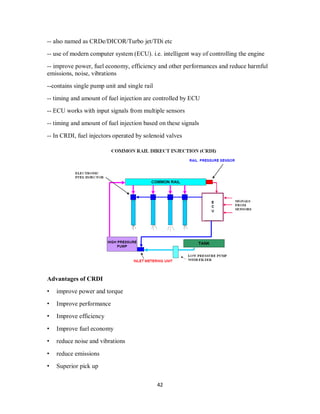
Common rail direct injection(CRDi)
technology used in diesel engines
42
-- also named as CRDe/DICOR/Turbo jet/TDi etc
-- use of modern computer system (ECU). i.e. intelligent way of controlling the engine
-- improve power, fuel economy, efficiency and other performances and reduce harmful
emissions, noise, vibrations
--contains single pump unit and single rail
-- timing and amount of fuel injection are controlled by ECU
-- ECU works with input signals from multiple sensors
-- timing and amount of fuel injection based on these signals
-- In CRDI, fuel injectors operated by solenoid valves
Advantages of CRDI
• improve power and torque
• Improve performance
• Improve efficiency
• Improve fuel economy
• reduce noise and vibrations
• reduce emissions
• Superior pick up
43
• It helps to overcomes the difficulty in cold starting
Disadvantages of CRDI
• Initial cost high
• Costly spare parts
• More maintenances
• High maintenance cost
COMBUSTION CHAMBERS
The design of combustion chamber has an important influence upon the engine
performance and its knock properties. The design of combustion chamber involves the
shape of the combustion chamber, the location of the sparking plug and the disposition
of inlet and exhaust valves. Because of the importance of combustion chamber design,
it has been a subject of considerable amount of research and development in the last
fifty years. It has resulted in raising the compression ratio from 4: 1 before the First
World War period to 8: 1 to 11:1 in present times with special combustion Chamber
designs and suitable anti-knock fuels.
BASIC REQUIREMENTS OF A GOOD COMBUSTION CHAMBER
High power output
High thermal efficiency and low specific fuel consumption
Smooth engine operation
Reduced exhaust pollutants.
Combustion chambers for SI engines
important considerations
1. production of turbulence
2. location of spark plug
3. surface to volume ratio
Types of combustion chambers in SI engines
1. Side valve type
simple, cheapest , less efficient and was used for lower compression ratio and not commonly
used
44
2. Wedge type
single row valves are tilted to accommodate the sloping roof of the chamber
--Spark plug is located on the thick side of the wedge
-- at the end of compression stroke, the piston comes near the quench area cause turbulence
-- due to turbulence high quality mixing of charge
-- fast, smooth and uniform combustion
-- spark plug is placed in the end way from
quench area where turbulence is very high
45
3. Inverted bath tub type
another form of wedge type chamber
-- high turbulence and flame spreads rapidly
4. Flat head type
cylinder head is flat
--entire combustion chamber is placed in the piston crown
--high combustion efficiency ,suitable for high C.R.
-- heat dissipated mainly through piston
46
5. Hemispherical type
-- shape of combustion chamber is close to hemispherical
-- efficient and compact
-- spark plug placed on centre, valves are placed in the slant position
--inlet and exhaust valves are on different sides ( two cam shafts)
-- short flame travel distance
-- no obstruction in the flow of gases (high volumetric efficiency)
-- high production cost, high rate of pressure rise
-- best suited for racing cars
6. Stratified charge type
-- some of the layers have rich mixture and others have lean mixture
-- overall charge has very lean A/F mixture compared to ordinary engine
-- in the spark plug region –rich mixture, remaining portion- lean
-- using this type petrol engine can run with A/F ratio of 150:1
7. Multi valve type
-- provides larger total valve capacity for a given cylinder bore size
-- high volumetric efficiency high flow rate, better combustion reduced emission, better
performance more fuel economy
47
-- high cost and complex construction
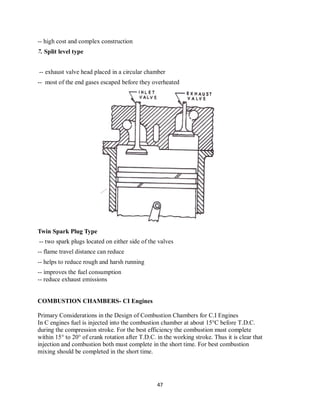
7. Split level type
-- exhaust valve head placed in a circular chamber
-- most of the end gases escaped before they overheated
Twin Spark Plug Type
-- two spark plugs located on either side of the valves
-- flame travel distance can reduce
-- helps to reduce rough and harsh running
-- improves the fuel consumption
-- reduce exhaust emissions
COMBUSTION CHAMBERS- CI Engines
Primary Considerations in the Design of Combustion Chambers for C.I Engines
In C engines fuel is injected into the combustion chamber at about 15°C before T.D.C.
during the compression stroke. For the best efficiency the combustion must complete
within 15° to 20° of crank rotation after T.D.C. in the working stroke. Thus it is clear that
injection and combustion both must complete in the short time. For best combustion
mixing should be completed in the short time.
48
• In S.I engine mixing takes place in carburetor; however in C.I engines this has to be
done in the combustion chamber. To achieve this requirement in a short period is an
extremely difficult job particularly in high speed Cl. engines.
• From combustion phenomenon of C.I. engines it is evident that fuel-air contact must
be limited during the delay period in order to limit, the rate of pressure rise in the second
stage of combustion. This result can be obtained by shortening the delay to achieve
high efficiency and power the combustion must be completed when piston is nearer to
T.D.C., it is necessary to have rapid mixing of fuel and air dun the third stage of
combustion.
• The design of combustion chamber for C.I. engines must also take consideration of
injection system and nozzles to be used.
The considerations can be summarized as follows:
1. High thermal efficiency.
2. Ability to use less expensive fuel (multi-fuel).
3. Ease of starting.
4. Ability to handle variations in speed.
5. Smoothness of operation i.e. avoidance of diesel knock and noise.
6. Low exhaust emission.
7. Nozzle design.
8. High volumetric efficiency.
9. High brake Mean effective pressure
Role of air swirl in Diesel engine
Most important function of CI engine combustion chamber is to provide proper mixing of
fuel and air in short possible time. For this purpose an organized air movement called
air swirl is to be produced to produce high relative velocity between the fuel droplets
and air.
There are three basic methods of generating swirl in CI engine Combustion Chamber.
 By directing the flow of air during its entry to the cylinder known as Induction swirl.
This method is used in open combustion chamber.
 By forcing air through a tangential passage into a separate swirl chamber during the
compression stroke, known as Combustion swirl. This is used in swirl
chamber.
 By use of initial pressure rise due to partial combustion to create swirl and turbulence, known
as combustion induced swirl. This method is used in pre combustion
chamber and air cell chambers.
49
INDUCTION SWIRL
Swirl refers to a rotational flow within the cylinder about its axes. In a four stroke engine
induction swirl can be obtained either by careful formation of air intake passages or masking or
shrouding a portion of circumference of inlet valve. The angle of mask is from 90° to 140° of the
circumference. In two stroke engine, induction swirl is created by suitable inlet port forms.
Induction swirl can be generated using following methods.
1 Swirl is generated by constructing the intake system to give a tangential component to intake
flow as it enters the cylinder. This is done by shaping and contouring the intake manifold,
Swirl can be generated by masking one side of the inlet valve so that air is admitted only around
a part of the periphery of the valve and in the desired direction.
2 Swirl can also be generated by casting a lip over one side of the inlet valve.
Swirl generated by induction is very weak. Thus single orifice injection cannot provide the
desired air fuel mixing. Therefore, with Induction swirl, it is advisable to use a multiple-orifice
injector.
COMPRESSION SWIRL
Compression swirl is generated using swirl chamber. A swirl chamber is a divided chamber. A
divided combustion chamber is defined as one in which the combustion space is divided into two
or more compartments. Pressure difference between these chambers is created by restrictions or
throats. Very strong swirl can be generated using compression swirl.
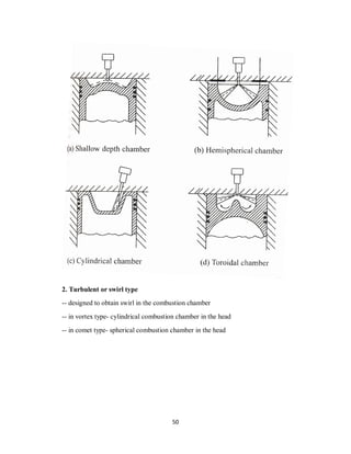
Types of ci engine combustion chambers are
1. Direct Injection Or Open Type
2. Turbulent or Swirl Type
3. Pre- chamber Type

1. Direct Injection Or Open Type
-- no separate combustion space in the head
-- the piston crown contains depression
-- lower ‘surface to volume ratio’
--multi hole injector is used
-- high efficiency
-- high pr: rise so rough running
50
2. Turbulent or swirl type
-- designed to obtain swirl in the combustion chamber
-- in vortex type- cylindrical combustion chamber in the head
-- in comet type- spherical combustion chamber in the head
51
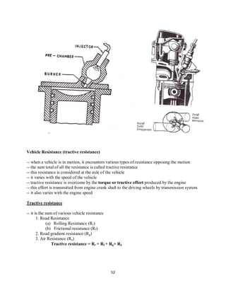
3. Pre- chamber Type
-- combustion space located both in head as well as in cylinder
-- 40% of combustion space in the cylinder head-pre chamber
-- main chamber is formed between cylinder head & piston crown
-- pre chamber connected to main through a restricted passage-burner
52
Vehicle Resistance (tractive resistance)
-- when a vehicle is in motion, it encounters various types of resistance opposing the motion
-- the sum total of all the resistance is called tractive resistance
-- this resistance is considered at the axle of the vehicle
-- it varies with the speed of the vehicle
-- tractive resistance is overcome by the torque or tractive effort produced by the engine
-- this effort is transmitted from engine crank shaft to the driving wheels by transmission system
-- it also varies with the engine speed
Tractive resistance
-- it is the sum of various vehicle resistance
1. Road Resistance
(a) Rolling Resistance (Rr)
(b) Frictional resistance (Rf)
2. Road gradient resistance (Rg)
3. Air Resistance (Ra)
Tractive resistance = Rr + Rf + Rg+ Ra
53
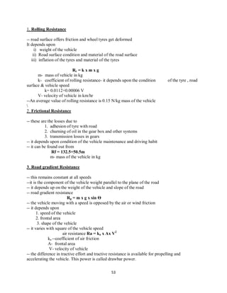
1. Rolling Resistance
-- road surface offers friction and wheel tyres get deformed
It depends upon
i) weight of the vehicle
ii) Road surface condition and material of the road surface
iii) inflation of the tyres and material of the tyres
Rr = k x m x g
m- mass of vehicle in kg
k- coefficient of rolling resistance- it depends upon the condition of the tyre , road
surface & vehicle speed
k= 0.0112+0.00006 V
V- velocity of vehicle in km/hr
--An average value of rolling resistance is 0.15 N/kg mass of the vehicle

2. Frictional Resistance
-- these are the losses due to
1. adhesion of tyre with road
2. churning of oil in the gear box and other systems
3. transmission losses in gears
-- it depends upon condition of the vehicle maintenance and driving habit
-- it can be found out from
Rf = 132.5+50.5m
m- mass of the vehicle in kg
3. Road gradient Resistance
-- this remains constant at all speeds
--it is the component of the vehicle weight parallel to the plane of the road
-- it depends up on the weight of the vehicle and slope of the road
-- road gradient resistance
Rg = m x g x sin Ѳ
-- the vehicle moving with a speed is opposed by the air or wind friction
-- it depends upon
1. speed of the vehicle
2. frontal area
3. shape of the vehicle
-- it varies with square of the vehicle speed
air resistance Ra = ka x Ax V2
ka --coefficient of air friction
A- frontal area
V- velocity of vehicle
-- the difference in tractive effort and tractive resistance is available for propelling and
accelerating the vehicle. This power is called drawbar power.
54
the work required at the axle to propel the vehicle
W = RT x V N km/hr
= (RT x V x1000) /(60x60) Nm/s or Watt
P = (RT x V ) /(60x60) kW
If the transmission efficiency between the engine crankshaft and the driving axle is Чtr
P = (RT x V ) / (3600x Чtr)
This is the power required for propel the vehicle

More Related Content

What's hot

Four wheel steering system
Four wheel steering systemFour wheel steering system
Four wheel steering systemThakur Singh
 
Automobile Industry - history, evolution & growth
Automobile Industry - history, evolution & growthAutomobile Industry - history, evolution & growth
Automobile Industry - history, evolution & growthRohith Sainoji
 
North america automabile industry in detroit
North america automabile industry in detroitNorth america automabile industry in detroit
North america automabile industry in detroitPrabhu Parmar
 
La petit histoire de l'autromobile
La petit histoire de l'autromobileLa petit histoire de l'autromobile
La petit histoire de l'autromobileJoyeux Nain
 
The evolution of the automobile
The evolution of the automobileThe evolution of the automobile
The evolution of the automobilejosephdesilva
 
Automobile history
Automobile historyAutomobile history
Automobile historyDanish Iqbal
 
Evolution Of Cars
Evolution Of CarsEvolution Of Cars
Evolution Of CarsEason Chan
 
Automobile History
Automobile HistoryAutomobile History
Automobile HistoryDanish Iqbal
 
Timeline Of Cars
Timeline Of CarsTimeline Of Cars
Timeline Of Carstheletterv
 
Evolution of automobiles
Evolution of automobilesEvolution of automobiles
Evolution of automobilesPradeep Yadav
 
Cars an evolution presentation
Cars an evolution presentationCars an evolution presentation
Cars an evolution presentationjasant
 
History of cars presentation
History of cars presentationHistory of cars presentation
History of cars presentationthe_al3lwi
 
Evolution of cars
Evolution of carsEvolution of cars
Evolution of carsscitch117
 
History of automobile
History of automobileHistory of automobile
History of automobileAhmedBasha41
 
Evolution of Cars by Team "Tends To Infinity"
Evolution of Cars by Team "Tends To Infinity"Evolution of Cars by Team "Tends To Infinity"
Evolution of Cars by Team "Tends To Infinity"ayonmondal3
 
Evan's PPT on Who made the first car
Evan's PPT on Who made the first carEvan's PPT on Who made the first car
Evan's PPT on Who made the first carjtiggs
 

What's hot (20)

Four wheel steering system
Four wheel steering systemFour wheel steering system
Four wheel steering system
 
Automobile Industry - history, evolution & growth
Automobile Industry - history, evolution & growthAutomobile Industry - history, evolution & growth
Automobile Industry - history, evolution & growth
 
North america automabile industry in detroit
North america automabile industry in detroitNorth america automabile industry in detroit
North america automabile industry in detroit
 
La petit histoire de l'autromobile
La petit histoire de l'autromobileLa petit histoire de l'autromobile
La petit histoire de l'autromobile
 
The evolution of the automobile
The evolution of the automobileThe evolution of the automobile
The evolution of the automobile
 
Automobile history
Automobile historyAutomobile history
Automobile history
 
Evolution Of Cars
Evolution Of CarsEvolution Of Cars
Evolution Of Cars
 
Automobile History
Automobile HistoryAutomobile History
Automobile History
 
Timeline Of Cars
Timeline Of CarsTimeline Of Cars
Timeline Of Cars
 
Evolution of cars
Evolution of carsEvolution of cars
Evolution of cars
 
Evolution of automobiles
Evolution of automobilesEvolution of automobiles
Evolution of automobiles
 
Cars an evolution presentation
Cars an evolution presentationCars an evolution presentation
Cars an evolution presentation
 
History of cars presentation
History of cars presentationHistory of cars presentation
History of cars presentation
 
Evolution of cars
Evolution of carsEvolution of cars
Evolution of cars
 
Evolution of cars
Evolution of carsEvolution of cars
Evolution of cars
 
History of automobile
History of automobileHistory of automobile
History of automobile
 
Evolution of Cars by Team "Tends To Infinity"
Evolution of Cars by Team "Tends To Infinity"Evolution of Cars by Team "Tends To Infinity"
Evolution of Cars by Team "Tends To Infinity"
 
MAIN REPORT
MAIN REPORTMAIN REPORT
MAIN REPORT
 
Evan's PPT on Who made the first car
Evan's PPT on Who made the first carEvan's PPT on Who made the first car
Evan's PPT on Who made the first car
 
Tienganh
TienganhTienganh
Tienganh
 

Similar to Automobile module1

COMPARATIVESTUDYBETWENTHERMAL ENGINE PROPULSION AND HYBRID PROPULSION
COMPARATIVESTUDYBETWENTHERMAL ENGINE PROPULSION AND HYBRID PROPULSIONCOMPARATIVESTUDYBETWENTHERMAL ENGINE PROPULSION AND HYBRID PROPULSION
COMPARATIVESTUDYBETWENTHERMAL ENGINE PROPULSION AND HYBRID PROPULSIONAJHSSR Journal
 
Automobile seminar aheg
Automobile seminar ahegAutomobile seminar aheg
Automobile seminar ahegSagar Kamble
 
58271192 trike
58271192 trike58271192 trike
58271192 trikeAman Jain
 
History automobile07
History automobile07History automobile07
History automobile07vontaviushurd
 
History of Electric Vehicle
History of Electric VehicleHistory of Electric Vehicle
History of Electric Vehiclesayalikhatangale
 
history-of-automobile.ppt
history-of-automobile.ppthistory-of-automobile.ppt
history-of-automobile.pptRASHVANDH1
 
document-part- (2).doc
document-part- (2).docdocument-part- (2).doc
document-part- (2).docBabirye Zahara
 
Hero Motors customer satisfsction
Hero Motors customer satisfsctionHero Motors customer satisfsction
Hero Motors customer satisfsctionMohit Agarwal
 
historyofautomobile-131222033601-phpapp01 (1).pptx
historyofautomobile-131222033601-phpapp01 (1).pptxhistoryofautomobile-131222033601-phpapp01 (1).pptx
historyofautomobile-131222033601-phpapp01 (1).pptxAryanYadav553427
 
How feasible are Electric Vehicles for the future?
How feasible are Electric Vehicles for the future?How feasible are Electric Vehicles for the future?
How feasible are Electric Vehicles for the future?Torben Haagh
 
Automotive industry
Automotive industryAutomotive industry
Automotive industrygsurya5050
 
report of air powered cars
report of air powered carsreport of air powered cars
report of air powered carssachin chaurasia
 
document-part- (1).doc
document-part- (1).docdocument-part- (1).doc
document-part- (1).docBabirye Zahara
 
ravi bambhroliya traveling
ravi bambhroliya travelingravi bambhroliya traveling
ravi bambhroliya travelingRavi Bambhroliya
 
Compressed air car technology
Compressed air car technologyCompressed air car technology
Compressed air car technologykeshav goyal
 
Automobile history
Automobile historyAutomobile history
Automobile historykgmahesh123
 

Similar to Automobile module1 (20)

COMPARATIVESTUDYBETWENTHERMAL ENGINE PROPULSION AND HYBRID PROPULSION
COMPARATIVESTUDYBETWENTHERMAL ENGINE PROPULSION AND HYBRID PROPULSIONCOMPARATIVESTUDYBETWENTHERMAL ENGINE PROPULSION AND HYBRID PROPULSION
COMPARATIVESTUDYBETWENTHERMAL ENGINE PROPULSION AND HYBRID PROPULSION
 
Automobile seminar aheg
Automobile seminar ahegAutomobile seminar aheg
Automobile seminar aheg
 
Motor cars
Motor carsMotor cars
Motor cars
 
58271192 trike
58271192 trike58271192 trike
58271192 trike
 
History automobile07
History automobile07History automobile07
History automobile07
 
History automobile07
History automobile07History automobile07
History automobile07
 
History of Electric Vehicle
History of Electric VehicleHistory of Electric Vehicle
History of Electric Vehicle
 
Teweti Major Project
Teweti Major ProjectTeweti Major Project
Teweti Major Project
 
history-of-automobile.ppt
history-of-automobile.ppthistory-of-automobile.ppt
history-of-automobile.ppt
 
document-part- (2).doc
document-part- (2).docdocument-part- (2).doc
document-part- (2).doc
 
Hero Motors customer satisfsction
Hero Motors customer satisfsctionHero Motors customer satisfsction
Hero Motors customer satisfsction
 
historyofautomobile-131222033601-phpapp01 (1).pptx
historyofautomobile-131222033601-phpapp01 (1).pptxhistoryofautomobile-131222033601-phpapp01 (1).pptx
historyofautomobile-131222033601-phpapp01 (1).pptx
 
How feasible are Electric Vehicles for the future?
How feasible are Electric Vehicles for the future?How feasible are Electric Vehicles for the future?
How feasible are Electric Vehicles for the future?
 
Automotive industry
Automotive industryAutomotive industry
Automotive industry
 
report of air powered cars
report of air powered carsreport of air powered cars
report of air powered cars
 
document-part- (1).doc
document-part- (1).docdocument-part- (1).doc
document-part- (1).doc
 
Complete final
Complete finalComplete final
Complete final
 
ravi bambhroliya traveling
ravi bambhroliya travelingravi bambhroliya traveling
ravi bambhroliya traveling
 
Compressed air car technology
Compressed air car technologyCompressed air car technology
Compressed air car technology
 
Automobile history
Automobile historyAutomobile history
Automobile history
 

Recently uploaded

Introduction to Multiple Access Protocol.pptx
Introduction to Multiple Access Protocol.pptxIntroduction to Multiple Access Protocol.pptx
Introduction to Multiple Access Protocol.pptxupamatechverse
 
High Profile Call Girls Nagpur Isha Call 7001035870 Meet With Nagpur Escorts
High Profile Call Girls Nagpur Isha Call 7001035870 Meet With Nagpur EscortsHigh Profile Call Girls Nagpur Isha Call 7001035870 Meet With Nagpur Escorts
High Profile Call Girls Nagpur Isha Call 7001035870 Meet With Nagpur Escortsranjana rawat
 
APPLICATIONS-AC/DC DRIVES-OPERATING CHARACTERISTICS
APPLICATIONS-AC/DC DRIVES-OPERATING CHARACTERISTICSAPPLICATIONS-AC/DC DRIVES-OPERATING CHARACTERISTICS
APPLICATIONS-AC/DC DRIVES-OPERATING CHARACTERISTICSKurinjimalarL3
 
The Most Attractive Pune Call Girls Budhwar Peth 8250192130 Will You Miss Thi...
The Most Attractive Pune Call Girls Budhwar Peth 8250192130 Will You Miss Thi...The Most Attractive Pune Call Girls Budhwar Peth 8250192130 Will You Miss Thi...
The Most Attractive Pune Call Girls Budhwar Peth 8250192130 Will You Miss Thi...ranjana rawat
 
Coefficient of Thermal Expansion and their Importance.pptx
Coefficient of Thermal Expansion and their Importance.pptxCoefficient of Thermal Expansion and their Importance.pptx
Coefficient of Thermal Expansion and their Importance.pptxAsutosh Ranjan
 
Booking open Available Pune Call Girls Koregaon Park 6297143586 Call Hot Ind...
Booking open Available Pune Call Girls Koregaon Park  6297143586 Call Hot Ind...Booking open Available Pune Call Girls Koregaon Park  6297143586 Call Hot Ind...
Booking open Available Pune Call Girls Koregaon Park 6297143586 Call Hot Ind...Call Girls in Nagpur High Profile
 
Sheet Pile Wall Design and Construction: A Practical Guide for Civil Engineer...
Sheet Pile Wall Design and Construction: A Practical Guide for Civil Engineer...Sheet Pile Wall Design and Construction: A Practical Guide for Civil Engineer...
Sheet Pile Wall Design and Construction: A Practical Guide for Civil Engineer...Dr.Costas Sachpazis
 
VIP Call Girls Service Hitech City Hyderabad Call +91-8250192130
VIP Call Girls Service Hitech City Hyderabad Call +91-8250192130VIP Call Girls Service Hitech City Hyderabad Call +91-8250192130
VIP Call Girls Service Hitech City Hyderabad Call +91-8250192130Suhani Kapoor
 
UNIT-III FMM. DIMENSIONAL ANALYSIS
UNIT-III FMM.        DIMENSIONAL ANALYSISUNIT-III FMM.        DIMENSIONAL ANALYSIS
UNIT-III FMM. DIMENSIONAL ANALYSISrknatarajan
 
Call Girls Service Nagpur Tanvi Call 7001035870 Meet With Nagpur Escorts
Call Girls Service Nagpur Tanvi Call 7001035870 Meet With Nagpur EscortsCall Girls Service Nagpur Tanvi Call 7001035870 Meet With Nagpur Escorts
Call Girls Service Nagpur Tanvi Call 7001035870 Meet With Nagpur EscortsCall Girls in Nagpur High Profile
 
OSVC_Meta-Data based Simulation Automation to overcome Verification Challenge...
OSVC_Meta-Data based Simulation Automation to overcome Verification Challenge...OSVC_Meta-Data based Simulation Automation to overcome Verification Challenge...
OSVC_Meta-Data based Simulation Automation to overcome Verification Challenge...Soham Mondal
 
Extrusion Processes and Their Limitations
Extrusion Processes and Their LimitationsExtrusion Processes and Their Limitations
Extrusion Processes and Their Limitations120cr0395
 
KubeKraft presentation @CloudNativeHooghly
KubeKraft presentation @CloudNativeHooghlyKubeKraft presentation @CloudNativeHooghly
KubeKraft presentation @CloudNativeHooghlysanyuktamishra911
 
The Most Attractive Pune Call Girls Manchar 8250192130 Will You Miss This Cha...
The Most Attractive Pune Call Girls Manchar 8250192130 Will You Miss This Cha...The Most Attractive Pune Call Girls Manchar 8250192130 Will You Miss This Cha...
The Most Attractive Pune Call Girls Manchar 8250192130 Will You Miss This Cha...ranjana rawat
 
MANUFACTURING PROCESS-II UNIT-2 LATHE MACHINE
MANUFACTURING PROCESS-II UNIT-2 LATHE MACHINEMANUFACTURING PROCESS-II UNIT-2 LATHE MACHINE
MANUFACTURING PROCESS-II UNIT-2 LATHE MACHINESIVASHANKAR N
 
(PRIYA) Rajgurunagar Call Girls Just Call 7001035870 [ Cash on Delivery ] Pun...
(PRIYA) Rajgurunagar Call Girls Just Call 7001035870 [ Cash on Delivery ] Pun...(PRIYA) Rajgurunagar Call Girls Just Call 7001035870 [ Cash on Delivery ] Pun...
(PRIYA) Rajgurunagar Call Girls Just Call 7001035870 [ Cash on Delivery ] Pun...ranjana rawat
 
Call Girls Service Nashik Vaishnavi 7001305949 Independent Escort Service Nashik
Call Girls Service Nashik Vaishnavi 7001305949 Independent Escort Service NashikCall Girls Service Nashik Vaishnavi 7001305949 Independent Escort Service Nashik
Call Girls Service Nashik Vaishnavi 7001305949 Independent Escort Service NashikCall Girls in Nagpur High Profile
 
Software Development Life Cycle By Team Orange (Dept. of Pharmacy)
Software Development Life Cycle By  Team Orange (Dept. of Pharmacy)Software Development Life Cycle By  Team Orange (Dept. of Pharmacy)
Software Development Life Cycle By Team Orange (Dept. of Pharmacy)Suman Mia
 

Recently uploaded (20)

Introduction to Multiple Access Protocol.pptx
Introduction to Multiple Access Protocol.pptxIntroduction to Multiple Access Protocol.pptx
Introduction to Multiple Access Protocol.pptx
 
High Profile Call Girls Nagpur Isha Call 7001035870 Meet With Nagpur Escorts
High Profile Call Girls Nagpur Isha Call 7001035870 Meet With Nagpur EscortsHigh Profile Call Girls Nagpur Isha Call 7001035870 Meet With Nagpur Escorts
High Profile Call Girls Nagpur Isha Call 7001035870 Meet With Nagpur Escorts
 
APPLICATIONS-AC/DC DRIVES-OPERATING CHARACTERISTICS
APPLICATIONS-AC/DC DRIVES-OPERATING CHARACTERISTICSAPPLICATIONS-AC/DC DRIVES-OPERATING CHARACTERISTICS
APPLICATIONS-AC/DC DRIVES-OPERATING CHARACTERISTICS
 
The Most Attractive Pune Call Girls Budhwar Peth 8250192130 Will You Miss Thi...
The Most Attractive Pune Call Girls Budhwar Peth 8250192130 Will You Miss Thi...The Most Attractive Pune Call Girls Budhwar Peth 8250192130 Will You Miss Thi...
The Most Attractive Pune Call Girls Budhwar Peth 8250192130 Will You Miss Thi...
 
Coefficient of Thermal Expansion and their Importance.pptx
Coefficient of Thermal Expansion and their Importance.pptxCoefficient of Thermal Expansion and their Importance.pptx
Coefficient of Thermal Expansion and their Importance.pptx
 
Booking open Available Pune Call Girls Koregaon Park 6297143586 Call Hot Ind...
Booking open Available Pune Call Girls Koregaon Park  6297143586 Call Hot Ind...Booking open Available Pune Call Girls Koregaon Park  6297143586 Call Hot Ind...
Booking open Available Pune Call Girls Koregaon Park 6297143586 Call Hot Ind...
 
Sheet Pile Wall Design and Construction: A Practical Guide for Civil Engineer...
Sheet Pile Wall Design and Construction: A Practical Guide for Civil Engineer...Sheet Pile Wall Design and Construction: A Practical Guide for Civil Engineer...
Sheet Pile Wall Design and Construction: A Practical Guide for Civil Engineer...
 
VIP Call Girls Service Hitech City Hyderabad Call +91-8250192130
VIP Call Girls Service Hitech City Hyderabad Call +91-8250192130VIP Call Girls Service Hitech City Hyderabad Call +91-8250192130
VIP Call Girls Service Hitech City Hyderabad Call +91-8250192130
 
UNIT-III FMM. DIMENSIONAL ANALYSIS
UNIT-III FMM.        DIMENSIONAL ANALYSISUNIT-III FMM.        DIMENSIONAL ANALYSIS
UNIT-III FMM. DIMENSIONAL ANALYSIS
 
Call Girls Service Nagpur Tanvi Call 7001035870 Meet With Nagpur Escorts
Call Girls Service Nagpur Tanvi Call 7001035870 Meet With Nagpur EscortsCall Girls Service Nagpur Tanvi Call 7001035870 Meet With Nagpur Escorts
Call Girls Service Nagpur Tanvi Call 7001035870 Meet With Nagpur Escorts
 
OSVC_Meta-Data based Simulation Automation to overcome Verification Challenge...
OSVC_Meta-Data based Simulation Automation to overcome Verification Challenge...OSVC_Meta-Data based Simulation Automation to overcome Verification Challenge...
OSVC_Meta-Data based Simulation Automation to overcome Verification Challenge...
 
Extrusion Processes and Their Limitations
Extrusion Processes and Their LimitationsExtrusion Processes and Their Limitations
Extrusion Processes and Their Limitations
 
KubeKraft presentation @CloudNativeHooghly
KubeKraft presentation @CloudNativeHooghlyKubeKraft presentation @CloudNativeHooghly
KubeKraft presentation @CloudNativeHooghly
 
Roadmap to Membership of RICS - Pathways and Routes
Roadmap to Membership of RICS - Pathways and RoutesRoadmap to Membership of RICS - Pathways and Routes
Roadmap to Membership of RICS - Pathways and Routes
 
DJARUM4D - SLOT GACOR ONLINE | SLOT DEMO ONLINE
DJARUM4D - SLOT GACOR ONLINE | SLOT DEMO ONLINEDJARUM4D - SLOT GACOR ONLINE | SLOT DEMO ONLINE
DJARUM4D - SLOT GACOR ONLINE | SLOT DEMO ONLINE
 
The Most Attractive Pune Call Girls Manchar 8250192130 Will You Miss This Cha...
The Most Attractive Pune Call Girls Manchar 8250192130 Will You Miss This Cha...The Most Attractive Pune Call Girls Manchar 8250192130 Will You Miss This Cha...
The Most Attractive Pune Call Girls Manchar 8250192130 Will You Miss This Cha...
 
MANUFACTURING PROCESS-II UNIT-2 LATHE MACHINE
MANUFACTURING PROCESS-II UNIT-2 LATHE MACHINEMANUFACTURING PROCESS-II UNIT-2 LATHE MACHINE
MANUFACTURING PROCESS-II UNIT-2 LATHE MACHINE
 
(PRIYA) Rajgurunagar Call Girls Just Call 7001035870 [ Cash on Delivery ] Pun...
(PRIYA) Rajgurunagar Call Girls Just Call 7001035870 [ Cash on Delivery ] Pun...(PRIYA) Rajgurunagar Call Girls Just Call 7001035870 [ Cash on Delivery ] Pun...
(PRIYA) Rajgurunagar Call Girls Just Call 7001035870 [ Cash on Delivery ] Pun...
 
Call Girls Service Nashik Vaishnavi 7001305949 Independent Escort Service Nashik
Call Girls Service Nashik Vaishnavi 7001305949 Independent Escort Service NashikCall Girls Service Nashik Vaishnavi 7001305949 Independent Escort Service Nashik
Call Girls Service Nashik Vaishnavi 7001305949 Independent Escort Service Nashik
 
Software Development Life Cycle By Team Orange (Dept. of Pharmacy)
Software Development Life Cycle By  Team Orange (Dept. of Pharmacy)Software Development Life Cycle By  Team Orange (Dept. of Pharmacy)
Software Development Life Cycle By Team Orange (Dept. of Pharmacy)
 

Automobile module1

  • 1. 1 AUTOMOBILE ENGINEERING1 Automobile engineering is an applied science that includes elements of Mechanical engineering, Electrical engineering, Electronic Engineering, Software Engineering and Safety engineering as applied to the design, manufacture and operation of automobiles, buses and trucks and their respective engineering subsystems. The word automobile comes, via the French automobile, from the Ancient Greek word (autos, "self") and the Latin mobiles ("movable"); meaning a vehicle that moves itself, rather than being pulled or pushed by a separate animal or another vehicle. The alternative name car is believed to originate from the Latin word carrus or carrum ("wheeled vehicle) What is an Automobile? The automobile is a self propelled vehicle that travels on land. It usually has four wheels. An engine provides the power to move the vehicle. As the name implies, it is a mobile or moving power unit on road. Self- propelled means unit which contains its own power source, necessary for moving, within itself .As a vehicle ,it is used for transportation of passenger and goods. 1.1. INTRODUCTION Transportation has become unavoidable for the social and economic development of mankind. Men animals and various goods are transported from one place to another by different modes of transport. 1. Water transport such as ships, boats, hovercrafts. 2. Air transport such as aeroplanes, helicopters. 3. Space transport such as space crafts. 4. Land transport such as railways, roadways. Road transport is most popular mode of travelling and transportation and accounts for nearly 70% of all modes of transport available. Motor vehicle is a self-propelling unit which carries the passengers or goods and ply on the road surface. The motor vehicle or automobile or auto vehicle is driven by an internal combustion engine or a prime mover operated by combustion of a fuel or electricity or a battery. There is a wide range of automobiles designed for specific duty. The two-wheeler mopeds, scooters, motor-cycle are used by individuals, four-wheeler cars and jeeps are family vehicles, vans (minibus) and buses serve the society by transporting people, trucks are required for carrying goods, tractors are field vehicles, bulldozers are used in construction work and gun- carriage is involved in military operations. The automobile has created a new revolution in the history of mankind. The modern age is called “auto age” as the impact of the society has been very profound.
  • 2. 2 1.2. HISTORY OF AUTOMOBILE DEVELOPMENT The history of automobile development and growth is very fascinating. It runs together with the history of development of engines. This can studied as under. 1.2.1. European Development The awn of automobile history dates back to 1770 when a Frenchman, Nicholas Carnot, built the first road vehicle propelled by its own power. The French artillery officer built a three-wheeler steam tractor for handling a canon. It could work for 15 minutes only and attained a sped of about 2.5 mph. The automobile or the car as we now today evolved from the horse-drawn carriage, and perhaps the 19th century tricycle; but as the years went by it gradually lost its likeness to any of its progenitors. The saga of the car really began as recently as 1860, when Jean Etienne Lenoir, a Belgian inventor, built the first practicable gas engine. Etienne’s engine was fed on a mixture of coal gas and air and no compression meant that it was not efficient. The next significant development came in 1876 when Count Nikolous Otto, a German engineer, successfully applied the four- stroke principle which enabled the charge to be compressed with significantly better performance. At about the same time petrol came to substitute the coal gas. During the 1880’s Germany was the hub of automobile development with Gottlieb Daimler and Carl Benz at the helms of affairs. They were building their cars for sale in 1886. The engine was placed in the front of the chassis, hooked up to a sliding gear transmission, brake pedal, clutch and acceleration were incorporated. By the turn of the century, designers began increasing the number of the cylinder and a prototype in-line 6-cylinder engine appeared in 1902. The design improvement awakened the public to the next six years, production and sale of these vehicles became a business. The early 1920’s saw the beginning of a period of gradual change and refinement in automobile design. The spark ignition engine was the power plant of motor vehicle and kicked out steam and electrical rivals. Water-cooled engine were almost certain. The engine were located in the front of the chassis. The poppet valve was used in every engine design. Major improvements have been made in every car feature. The main design requirements emphasized on production of reliable vehicles to function at all times under all condition which would be increasingly comfortable to ride in and easy to operate. 1.2.2. American Development When Europe was struggling to make his vehicle run, came the period, in which the development of mass-production methods permitting lower prices played a dominant role in America. In 1908 Ford started off his Model T with an initial run of 2,000 vehicles, an output unheard of at that time. Ever since, the correlation of design and production efficiency has influenced the trend of modern vehicle construction and popularized the use of automobiles. The life of tyres has been increased, independent front-wheel suspension has been introduced; four-wheel hydraulic brakes have been incorporated, the higher compression ralios and availability of new materials have helped to enhance power-weight ratio.
  • 3. 3 Substantial progress has been made after the second world war in every car feature such as reliability and safety, ease and comfort, economy of operation, pleasing appearance. Safety and exhaust emission were the additional features. Research and development continue to produce computer controlled vehicles powered with nuclear engines and fuel cells. 1.2.3. Indian Development At the end of 1900, the cars arrived in India and were used by Britishers and Kings of states. In pre-Independent India, cars were imported and it was only in 1946, Hindustan Motors was set up in Calcutta. It was followed by Premier Automobiles in 1947 to produce cars and Mahindra and Mahindra in 1949 to produce jeeps in Bombay. Standard Motors was established in Madras in 1950. The industrial giant, Tata introduced a plant for the manufacture was started in India with foreign collaborations and as such could not contribute much to improve the design and manufacture of new cars. The production of all the cars was far below the nation’s demand. Maruti Udyog Limited was emphasized in 1982 in collaboration with Suzuki of Japan to manufacture small cars. It has helped to automobiles the country. New models have been introduced by various companies in recent years which have the latest features and machines available for all income group of the country’s population. ENGINES INTRODUCTION Heat engines absorb energy in the form of heat and convert part of it into mechanical energy and deliver it as work, the balance being rejected as heat. These devices derive the heat energy from the combustion of a fuel. Based on the location of the combustion process, heat engines are classified into internal combustion and external combustion engines. Internal combustion engines (IC engines) are those where the combustion of the fuel takes place inside the engines – eg. automobile engines. In the case of external combustion engines, combustion of fuel occurs outside the engines and the working gas so heated is then admitted into the engines for conversion and work extraction – eg. steam generated in a boiler is then admitted to steam engines for producing work. Internal combustion Engines Advantages:- - Greater thermal efficiency . - Lower weight to output ratio. - Lower initial cost. - Compact and most suitable for portable applications. - Lesser cooling requirements.
  • 4. 4 Classification of I C Engines:- i) On the basis of Basic engine design:- (1) Reciprocating (2) Rotary (Wankel) (ii) On the basis of Working cycle:- (1) Otto cycle (SI Engine) (2) Diesel cycle (C I Engine) (iii) On the basis of Strokes:- (1) Four stroke Engine (2) Two stroke Engine (iv) On the basis of Fuel:- (1) Petrol (2) Diesel, CNG& LPG (v) On the basis of Fuel supply:- (1) Carbureted types (2) Injection types (vi) On the basis of Ignition:- (1) Battery ignition (2) Magneto ignition (vii) On the basis of Cooling Method:- (1) Water cooled (2) Air cooled (viii) On the basis of cylinder arrangement:- (1) In line Engine (2) V Engine (3) Radial Engine etc. (ix) On the basis of valve location:- (1) Overhead valve (2) Side valve (x) On the basis of Application:- (1) Automobile engines (2) Marine engines (3) Aircraft engines
  • 5. 5 (4) Industrial engines 1. In-line engines The cylinders are attached to the same crank case, one cylinder behind the other with their axes parallel. These cylinders may be vertical, horizontal or inverted. 4-6 water cooled cylinders arranged in-line are very popular in automobiles.
  • 6. 6 Four banks of cylinders with single crankshaft and single crank case are arranged. 4. Radial engines The cylinders are radically arranged like the spokes of a wheel and are connected to a single crankshaft. It has a relatively short, stiff crankshaft and compact crankcase. These operate on a single crank throw and are mostly used as air-cooled engines for aircrafts.
  • 7. 7
  • 8. 8
  • 9. 9 Parts of an IC engine The main components of a standard IC engine are briefly described below: 1. Cylinder head. • It is attached to the top surface of the cylinder block • gaskets are used to provide a tight leak proof joint at the interface of the head and the block • the cylinder head forms a combustion chamber above each cylinder.
  • 10. 10 • It also contains valve guides, valve seats, coolant jackets and threaded holes for spark plugs or injection • materials used- gray cast iron or aluminium alloys 2. Cylinder block • The basic framework of the engine • It houses the engine cylinders • There are passages for the circulation of coolant • carries lubrication oil to various components through drilled passages • It support and encloses the moving parts • All static & dynamic loads, unbalanced forces and torsional vibrations are transmitted to frame through this block • It subjected to extreme temp: gradient • Materials used- gray cast iron & Aluminium alloys 3. Piston. The functions 1. transmit the force of explosion to the crankshaft. 2. form a seal so that the high pressure gases in the combustion chamber do not escape into the crankcase. 3. serve as a guide and a bearing for small end of the connecting rod. desirable characteristics Silent in operation Seizure does not occur Sufficient resistance to corrosion Lighter in weight Materials for piston 1. Aluminium cast iron
  • 11. 11 4. Connecting rod. • it is the connection between the piston and crank shaft • Its function is to convert the reciprocating motion of the piston into the rotary motion of the crankshaft. • two rod-ends, called the small end and the big end. • The small end of the rod is connected to the piston pin. • The big end connected to the crankpin • It usually has “ I ” beam cross section • It is made of forged steel 5. Crankshaft. • Crankshaft is the engine component from which the power is taken. • It is the part on to which the reciprocating motion is converted into rotating motion • It receives the power from the connecting rods in the designated sequence 6. Crank case • base of the engine • supports the crank shaft and engine • attached to the bottom face of the cylinder block
  • 12. 12 • The oil pan and the bottom part of the cylinder block together are called crank case • Material used-aluminium alloys • It provide the support for the main journals and bearings 7 Oil pan or sump • Oil pan or sump forms the bottom half of the crankcase. • It is attached to the crankcase through set screws and with a gasket to make the joint leak-proof. • Its functions are : I. To store the oil for the engine lubricating system. 2. To collect the return oil draining from the main bearings or from the cylinder walls. 3. To provide for cooling of the hot oil in the sump by transfer of heat to the outsider air stream 8 Gaskets • Gaskets are used to provide a tight fitting joint between two surfaces • Should be able to with stand high pressure and high temperature Requirements Resistance. Due to temperature changes or vibrations the joint may become slightly loose. The gasket should be able to retain its sealing force under this situation. Impermeability. The gaskets must be impermeable to the fluid it is expected to seal. Resistance to chemical attack. The gaskets should be resistant to the chemicals with which it may come into contact Resistance to operating conditions. As an example, the cylinder head gasket should be resistant to widely fluctuating and pulsating internal pressures and temperatures and exposure to flame
  • 13. 13 Important gaskets 1. Copper- asbestos gasket, 2. steel – asbestos gasket, 3. steel – asbestos-copper gasket, 4. single steel ridged gasket, 5. stainless steel gasket 9 Piston rings fitted into the grooves of the piston to maintain good seal Functions • To form a seal for the high pressure gases from the combustion chamber against leak into the crank case. • To provide easy passage for heat flow from the piston crown to the cylinder walls. • To maintain sufficient lubricating oil on cylinder walls throughout the length of the piston travel Types of rings compression rings: -- fitted into the top grooves -- it seal in the air fuel mixture as it compressed and also the combustion pressure as it burns -- It also transfer heat from piston crown to the cylinder walls.
  • 14. 14 2. Oil control rings: -- fitted into the lower groove of the piston -- Controls excessive amount of oil from passing between ring face and the cylinder walls. 10 Cylinder liners • The problem of cylinder wear in the engine solved by the use of cylinder liners • Liners are in the form of barrels made of special alloy iron • liners can be replaced when these are worn out Two types :- dry liners & wet liners 1. Dry liners: This type of liner is made in the shape of a barrel with flange at the top which keeps it into position. Both outside and inside should be machined very accurately It is not in direct contact with the cooling water 2. Wet liner: -- It is in direct contact with cooling water on the outside and hence the entire outer surface does not require very accurate machining. But the water-tight joints have to be provided.
  • 15. 15 11 Camshaft • Carries cams for - each valve and for the operation of fuel pump & ignition system • It is driven by the crank shaft at half of its own speed • Cam is a rotating member which imparts reciprocating motion to follower at right angles to the cam axis. • The camshaft controlling the opening and closing intervals of the inlet and exhaust valve • Camshaft consist of a number of cams at suitable angular positions for operating the valves. 12 Flywheel • The purpose of the flywheel is to store up energy • mounted on the crank shaft • Stores excess energy during the power stroke and returns that energy during other strokes & maintains const O/p torque • The size of the flywheel varies with the number of cylinders and general construction of the engine.
  • 16. 16 Nomenclature of I C Engines 1) Cylinder bore (D):- The nominal inner diameter of the working cylinder. 2) Piston area (A):- Cross sectional area of the piston. This is equal to cylinder bore area 3) Stroke (L):- The nominal distance between TDC & BDC 4) Dead Center: - End points of the strokes (i) Top dead center (TDC):- Farthest position of piston from crank shaft. It is also called, Inner Dead Center (IDC) (ii) Bottom Dead Center (BDC):- Nearest position of piston form crank shaft. It is also called Outer Dead Center (ODC) 5) Swept Volume (Vs) :- The nominal volume generated by the piston when travelling from one dead center to next. i.e., TDC to BDC , Vs = A×L 6) Clearance Volume (Vc):- The nominal volume or volume for combustion, which is just above the TDC. 7) Cylinder Volume (V) :- The sum of swept volume and clearance volume. V = Vs + Vc 8) Compression ratio (r) :- Ratio of cylinder volume to clearance volume; V r Vc = Four Stroke I C Engines In a four-stroke engine, the cycle of operations is completed in four strokes of the piston or two revolutions of the crankshaft. During the four strokes, there are five events to be Completed, viz., suction, compression, combustion, expansion and exhaust. Each stroke consists of 180° of
  • 17. 17 crankshaft rotation and hence a four-stroke cycle is completed through 720° of crank rotation. The cycle of operation for an ideal four-stroke SI engine consists of the following four strokes: 1. Suction Stroke (0 -180°) 2. Compression Stroke (180°-360°) 3. Expansion Stroke (360°-540°) 4. Exhaust Stroke (540°-720°) Working principle of a Four Stroke SI Engine Suction or Intake Stroke: Suction stroke starts when the piston is at the top dead centre and about to move downwards. The inlet valve is open at this time and the exhaust valve is closed. Due to the suction created by the motion of the piston towards the bottom dead centre, the charge consisting of fuel-air mixture is drawn into the cylinder. When the piston reaches the bottom dead centre the suction stroke ends and the inlet valve closes. The charge taken into the cylinder during the suction stroke is compressed by the return stroke of the piston. During this stroke both inlet and exhaust valves are in closed position. The mixture that fills the entire cylinder volume is now compressed into the clearance volume. At the end of the compression stroke the mixture is ignited with the help of a spark plug located on the cylinder head. In ideal engines it is assumed that burning takes place instantaneously when the piston is at the top dead centre and hence the burning process can be approximated as heat addition at constant volume. During the burning process the chemical energy of the fuel is converted into heat energy producing a temperature rise of about 2000 °C The pressure at the end of the combustion process is considerably increased due to the heat release from the fuel. At the end of the expansion stroke the exhaust valve opens and the inlet valve remains closed. The pressure falls to atmospheric level a part of the burnt gases escape. The piston starts moving from the bottom dead centre to top dead centre and sweeps the burnt gases out from the cylinder almost at atmospheric pressure. The exhaust valve closes when the piston reaches T DC. At the end of the exhaust stroke and some residual gases trapped in the clearance volume remain in the cylinder. These residual gases mix with the fresh charge coming in during the following cycle, forming its working fluid. Each cylinder of a four stroke engine completes the above four operations in two engine revolutions, one revolution of the crankshaft occurs during the suction and compression strokes and the second revolution during the power and exhaust strokes. Thus for one complete cycle there is only one power stroke while the crankshaft turns by two revolutions. For getting higher output from the engine the heat release should be as high as possible and the heat rejection should be as small as possible.
  • 18. 18 Ideal P-V Diagram of Four Stroke S I Engine Four Stroke C I Engine:- The four-stroke CI engine is similar to the four-stroke SI engine but it operates at a much higher compression ratio. The compression ratio of an SI engine is between 6 and 10 while for a CI engine it is from 16 to 20. In the CI engine during suction stroke, air, instead of a fuel-air mixture, is inducted. Due to the high compression ratio employed, the temperature at the end of the compression stroke is sufficiently high to self ignite the fuel which is injected into the combustion chamber. In CI engines, a high pressure fuel pump and an injector are provided to inject the fuel into the combustion chamber. The carburetor and ignition system necessary in the SI engine are not required in the CI engine. The ideal sequence of operations for the four-stroke CI engine is as follows: i. Suction Stroke: Air alone is inducted during the suction stroke. During this stroke intake valve is open and exhaust valve is closed. ii. Compression Stroke: Air inducted during the suction stroke is compressed into the clearance volume. Both valves remain closed during this stroke. iii. Expansion Stroke: Fuel injection starts nearly at the end of the compression stroke. The rate of injection is such that combustion maintains the pressure constant in spite of the piston movement on its expansion stroke increasing the volume. Heat is assumed to have been added at constant pressure. After the injection of fuel is completed (i.e. after cutoff) the products of combustion expand. Both the valves remain closed during the expansion stroke. iv. Exhaust Stroke: The piston traveling from EDC to TDC pushes out the products of combustion. The exhaust valve is open and the intake valve is closed during this stroke. Ideal P-V Diagram of Four Stroke C I Engine
  • 19. 19 Comparison of S I and C I Engine 1. Basis of Cycle Otto Cycle Constant Volume heat addition Diesel Cycle Constant pressure heat addition 2. Fuel highly volatile non-volatile 3. Introduction of fuel air + fuel introduced into the cylinder only air introduced into the cylinder 4. Ignition Spark plug Self ignition due to high temperature 5. Compression ratio 6 - 10 Bikes ,cars 16 - 20 Diesel cars & trucks 6.Speed Due to light weight, they are high speed engine low speed engines 7. ηth Because of lower CR ηth is lower th r 1 1 r − η = ηth is higher or ( ) c r 1 c r 11 1 r r 1r −  − −   −   8. Weight lower peak pressure, engines are lighter Heavier Actual indicating diagram of S I Engine Two-stroke Engine As already mentioned, if the two unproductive strokes, viz., the suction and exhaust could be served by an alternative arrangement, especially without the movement of the piston then there
  • 20. 20 will be a power stroke for each revolution of the crankshaft. In such an arrangement, theoretically the power output of the engine can be doubled for the same speed compared to a four-stroke engine. Based on this concept, Dugald Clark (1878) invented the two-stroke engine. In two-stroke engines the cycle is completed in one revolution of the crankshaft. The main difference between two-stroke and four stroke engines is in the method of filling the fresh charge and removing the burnt gases from the cylinder. In the four-stroke engine these operations are performed by the engine piston during the suction and exhaust” strokes respectively. In a two- stroke engine, the filling process is accomplished by the charge compressed in crankcase or by a blower. The induction of the compressed charge moves out the product of combustion through exhaust ports. Therefore, no piston strokes are required for these two operations. Two strokes are sufficient to complete the cycle, one for compressing the fresh charge and the other for expansion or power stroke. The air or charge is inducted into the crankcase through the spring loaded inlet valve when the pressure in the crankcase is reduced due to upward motion of the piston during compression stroke. After the compression and ignition, expansion takes place in the usual way. During the expansion stroke the charge in the crankcase is compressed. Near the end of the expansion stroke, the piston uncovers the exhaust ports and the cylinder pressure drops to atmospheric pressure as the combustion products leave the cylinder. Further movement of the piston uncovers the transfer ports, permitting the slightly compressed charge in the crankcase to enter the engine cylinder. The top of the piston has usually a projection to deflect the fresh charge towards the top of the cylinder before flowing to the exhaust ports. This serves the double purpose of scavenging the
  • 21. 21 upper part of the cylinder of the combustion products and preventing the fresh charge from flowing directly to the exhaust ports. Advantages of two-stroke engines 1. A two-stroke engine has a power stroke every revolution of the crankshaft. Therefore its power to weight ratio is higher than that of a four-stroke engine. 2. The torque is more uniform in a two-stroke engine, hence it requires a lighter flywheel than that for a four-stroke engine. 3. Two-stroke engines are simpler in construction than four-stroke engines due to the absence of valves and their operating mechanism. 4. The friction loss is less in two-stroke engines, therefore it gives higher mechanical efficiency than four-stroke engines. 5. The capital cost of two-stroke engines is less than that of four-stroke engines. 6. The starting of two-stroke engines is easier than starting of four-stroke engines. Disadvantages of two-stroke engines 1. The overall efficiency is less than that of four-stroke engines due to (i) inadequate scavenging as some combustion products are left in the cylinder (ii) loss of fresh charge during scavenging, and (iii) less effective compression ratio for same stroke long. 2. The engine is always overheated due to power stroke in every revolution. 3. The consumption of lubricating oil is higher as it is subjected to higher temperatures. 4. The exhaust of two-stroke engines is noisier needing more baffling in the silencers. Parts Cylinders → cast iron, alloy steel Cylinder head → cast iron, aluminium alloy Piston → cast iron, aluminium alloy Piston rings → silicon, cast iron Judger pin → steel Valves → specially alloy steels Connecting rod → steel Crank shaft → alloy steel Crank case → steel, cast iron Cylinder timer → nickel alloy steel, cast iron Bearing → white metal
  • 22. 22 Comparison of Four stroke and two stroke cycle engines 1. The cycle is completed in Four stroke of the piston or two revolutions. i.e., one power stroke is obtained in every two revolutions. 2. Turning moment is not so uniform and hence heavier flywheel is needed. 3. Power produced for same size of engine is small. 4. Four stroke engine contains valves and valve mechanisms. 5. Heavy weight and complication of valve mechanism. 6. Volumetric efficiency more due to greater time of induction. (one stroke for suction stroke) 7. Thermal efficiency high. 8. Cars, buses, trucks, industries etc. 1. The cycle is completed in two-strokes of the piston or in one revolution of crankshaft. i.e., one power stroke is obtained in one revolution of crank shaft. 2. More uniform turning movements and hence lighter flywheel is needed. 3. Power produced for same size of engine is more (theoriticaly twice, actually about 1.3 times) 4. No valves but only ports. 5. Light weight and simplicity due to the absence of valve mechanism. 6. Less volumetric efficiency due to lesser time for induction. 7. Thermal efficiency lower 8. Compact scooters, bikes etc (petrol) Two-stroke diesel engines used in very large sizes, more than 60 cm base. (ship) because low weight and compactness. eg:- Marine Engine, Fork lift etc. WANKEL ENGINE Dr. Felix Wankel was the founder of the first successful rotary engine. He was invented in 1957. The engine has a three lobe rotor which is driven eccentrically in a casing in such a way that there are thrice separate volumes trapped between the rotor and the casing. These three volumes perform induction, compression, combustion, expansion and exhaust process in sequence. Sealing, seal wear ad heat transfer were some of the development problems of Wankel engines. The reciprocating piston has been replaced by a triangular-shaped rotor. With on complete revolution of the rotor the power pulses will occur. There are three complete four-stroke cycles (revolutions of a rotor). The gear ratios are such that the output shaft rotates at three times the speed of rotor.
  • 23. 23 -Passenger cars are manufactured by Mazda, Japan & Rolls Royees Ltd. - Compression ratio is 18. Advantages:- (1) Power output/weight ratio is higher because of its compactness. (2) Simple in design - no valve problems. (3) No. of parts is much less than a conventional four stroke S I engine. Therefore it is less costly. (4) Mechanical efficiency is better because of lower frictional losses. Disadvantages:- (1) The engine has lower efficiency because higher heat transfer rate. (2) Exhaust emissions are higher because of poor combustion chamber shape. (3) There may be starting trouble. (4) Efficient operation of the engine requires efficient seal between two sides of the rotor and its casing. (5) The spark plug life is short without effective cooling. CARBURETION In the SI engine a combustible fuel-air mixture is prepared outside the engine cylinder. The process of preparing this mixture is called “carburetion”. The carburetor is a device which atomizes the fuel and mixes it with air and is most important part of the induction system. The pipe that carries the prepared mixture to the engine cylinder is called the intake manifold. During suction stroke vacuum is created in the cylinder which causes the air to flow through the carburetor and the fuel to be sprayed form the fuel jets. Because of the volatility of the fuel, most of the fuel vaporizes and forms a combustible fuel-air mixture. However, some of the larger droplets may reach the cylinder in the liquid form and must be vaporized and mixed with air
  • 24. 24 during the compression stroke before ignition by the electric spark. Four important factors which significantly affect the process of combustion are: 1. The time available for the preparation of the mixture. 2. The temperature of the incoming air of the intake manifold. 3. The quality of the fuel supplied. 4. The design of the induction system and combustion chamber. Properties of the air-fuel mixtures Range of air-fuel ratios = 7: 1 to 20 : 1 (1) Mixture requirement for maximum power - Maximum power is obtained at about 12.5: 1 A/F - Maximum energy is released when slightly excess fuel is introduced so that the oxygen present in t he cylinder is utilized. Disadvantage is partial combustion & less energy release. (2) Mixture requirement for maximum specific fuel consumption - Maximum efficiency occurs at as A/C of about 17:1 -Maximum efficiency occurs at a point slightly leaves than the chemically correct A/F ratio because excess air requires complete combustion of fuel when mixing is not perfect. A/P ratio (mass) Designation Power output Specific fuel consumption 18 - 22 16 - 18 15 approx. 12 - 14 Very weak Weak Chemically correct Rich Very Rich 40 % less 10% less 4% less Max. Power 20 % less Low Maximum (economical) 4% more 25 - 30% more 35% - 50% more
  • 25. 25 A SIMPLE CARBURETOR It consists of a float chamber nozzle with metering orifice, venturi and throttle valve. The float and a needle valve system maintain a constant height of petrol in the float chamber. During suction stroke air is drawn through the venturi .The air passing through the venturi increases in velocity and the pressure in the venturi threat decreases. From the float chamber, the fuel is fed to a discharge jet, the tip of which is located in the throat of the venturi. Now because the pressure in the float chamber is atmospheric and that at the discharge jet below atmospheric a pressure differential, called “carburetor depression, exists between them. This causes discharge of fuel into the air stream and the rate of flow is controlled or metered by the size of smaller section in the fuel depression is 4 - 5cm below atmospheric.” Essential Parts of a Carburetor A carburetor consists essentially of the following parts, viz. i. Fuel strainer ii. Float chamber
  • 26. 26 iii. Main fuel metering and idling nozzles iv. Choke and throttle The various parts mentioned above are discussed briefly in the following section. The Fuel Strainer As the gasoline has to pass through a narrow nozzle exit there is every possibility that the nozzle may get clogged during prolonged operation of the engine. To prevent possible blockage of the nozzle by dust particles, the gasoline is filtered by installing a fuel strainer at the inlet to the float chamber. The strainer consists of a fine wire mesh or other type of filtering device, cone shaped or cylindrical shaped. The Float Chamber The function of a float chamber in a carburetor is to supply the fuel to the nozzle at a constant pressure head. This is possible by maintaining a constant level of the fuel in the float bowl. The float in a carburetor is designed to control the level of fuel in the float chamber. This fuel level must be maintained slightly below the discharge nozzle outlet holes in order to provide the correct amount of fuel flow and to prevent leakage of fuel from the nozzle when the engine is not operating. When the float rises with the fuel coming in, the fuel supply valve closes and stops the flow of fuel into the chamber. The Main Metering and Idling System The main metering system of the carburetor controls the fuel feed for cruising and full throttle operations (Fig.16.l0). It consists of three principal units: i. The fuel metering orifice through which fuel is drawn from the float chamber ii. The main discharge nozzle iii. The passage leading to the idling system The three functions of the main metering system are i. To proportion the fuel-air mixture ii. To decrease the pressure at the discharge nozzle exit iii. To limit the air flow at full throttle The automobiles fitted with SI engine require a rich mixture for idling and low speed operation. Usually air-fuel ratio of about 12:1 is required for idling. In order to provide such rich mixture, during idling, most of the modern carburetors incorporate special idling system is their construction. This system gets operational at starting, idling and very low speed running of the vehicle engine and is non operational when throttle is opened beyond 15% to 20%.
  • 27. 27 When the throttle is practically closed or marginally open, the very small quantity of air creates very little depression at the throat of the venturi, and that is not enough to suck any fuel from the nozzle. But very low pressure caused on the downstream side of the throttle due to suction stroke of the piston makes the fuel rise in the idling tube and the same is discharged through the idling discharge port, directly into the engine intake manifold. Due to the low pressure through idling air-bleed a small amount of air also is sucked. The idling air bleed mixes air with gasoline drawn from float chamber and helps it to vaporize and atomize it and pass on through the idle passage. The air bleed also prevents the gasoline in the float chamber getting drained off through the idling passage due to syphon action, when the engine is not in operation. With the opening of throttle and the engine passing through the idling range of operation, the suction pressure at the idle discharge port is not sufficient to draw the gasoline through the idling passage. And the idling system goes out of action. There after main air flow increases and the cruising range of operation is established. The desired fuel-air ratio for idling can be regulated by idling adjustment shown in Hot Idling Compensator Some modern automobiles have this system in the carburetor unit. Under certain extremely not operating conditions (with increased engine room temperature and also a high carburetor body temperature) there is a tendency for the idling mixture to become too rich. This causes idling instability. The hot idling compensator system (HIC) incorporates bi-metallic valve that admits air directly into the manifold in correct quantity when needed. Thus the mixture richness is adjusted and stable idling is ensured. The Choke and the Throttle When the vehicle is kept stationary for a long period during cool winter seasons, may be overnight, starting becomes more difficult. As already explained, at low cranking speeds and intake temperatures a very rich mixture is required to initiate combustion. Sometimes air-fuel ratio as rich as 9:1 is required. The main reason is that very large fraction of the fuel may remain as liquid suspended in air even in the cylinder. For initiating combustion, fuel-vapour and air in the form of mixture at a ratio that can sustain combustion is required. It may be noted that at very low temperature vapour fraction of the fuel is also very small and this forms combustible mixture
  • 28. 28 to initiate combustion. Hence, a very rich mixture must be supplied. The most popular method of providing such mixture is by the use of choke valve. This is simple butterfly valve located between the entrance to the carburetor and the venture throat .When the choke is partly closed, large pressure drop occurs at the venturi throat that would normally result from the quantity of air passing through the venturi throat. The very large depression at the throat inducts large amount of fuel from the main nozzle and provides a very rich mixture so that the ratio of the evaporated fuel to air in the cylinder is within the combustible limits. Sometimes, the choke valves are spring loaded to ensure that large carburetor depression and excessive choking does not persist after the engine has started, and reached a desired speed. This choke can be made to operate automatically by means of a thermostat so that the choke is closed when engine is cold and goes out of operation when engine warms up after starting. The speed and the output of an engine is controlled by the use of the throttle valve, which is located on the downstream side of the venturi. The more the throttle is closed the greater is the obstruction to the flow of the mixture placed in the passage and the less is the quantity of mixture delivered to .the cylinders. The decreased quantity of mixture gives a less powerful impulse to the pistons and the output of the engine is reduced accordingly. As the throttle is opened the output of the engine increases. Opening the throttle usually increases the speed of the engine. But this is not always the case as the load on the engine is also a factor. For example, opening the throttle when the motor vehicle is starting to climb a hill mayor may not increase the vehicle speed, depending upon the steepness of the hill and the extent of throttle opening. In short, the throttle is simply a means to regulate the output of the engine by varying the quantity of charge going into the cylinder. The choke and the throttle Types of Carburetors (1) Updraught type: - in which the air enters at the bottom and leaves at the top. So that the direction of its flow is upwards. The disadvantages of the updraught carburettor are that it must left the sprayed fuel droplet by air friction. Hence it must be designed to relatively small mixing tube and throat so that even at low engine speeds the air velocity is sufficient to left and carry the fuel particle along. Otherwise, the fuel droplets tend to
  • 29. 29 separate out. (2) Down draught Carburetor: - consists of a horizontal mixing tube with a float chamber on one side of it. By using a cross-draught carburetor in engines, one-right angled turn in the inlet passage is eliminated and the resistance to flow is reduced. (3) Constant choke Carburetor:- the air and fuel flow areas are always constant. But the pressure difference or depression which causes the flow of fuel and air. eg. Solex and Zenith Carburetors. (4) Constant Vacuum Carburetor:-variable chock carburetor - air and fuel flow areas are being varied as per the demand on the engine, while the vacuum is maintained to be always same. eg. S U and Carter carburetor. Multiple Venturi Carburettor Multiple Venturi system uses double or triple venturi. The boost venturi is located concentrically within the main venturis. The discharge edge of the boost venturi is located at the throat of the main venturi. The boost venturi is positioned up stream of the throat of the layer through the boost venturi. Now the pressure at the boost venturi exit equals the pressure at the main venturi throat. The fuel nozzle is located at the throat of the boost venturi. - high depression is created in the region of the fuel nozzle. - improved atomization are possible - better control
  • 30. 30 Multi Jet & Multi based Ventur’s carburetor Advantage 1. Duel carburetor supplies a charge of the mixture to the cylinder which is uniform in quality. 2. Distribution is better COOLING SYSTEMS OF IC ENGINES We know that in case of Internal Combustion engines, combustion of air and fuel takes place inside the engine cylinder and hot gases are generated. The temperature of gases will be around 2300-2500°C. This is a very high temperature and may result into burning of oil film between the moving parts and may result into seizing or welding of the same. So, this temperature must be reduced to about 150-200°C at which the engine will work most efficiently. Too much cooling is also not desirable since it reduces the thermal efficiency. So, the object of cooling system is to keep the engine running at its most efficient operating temperature. It is to be noted that the engine is quite inefficient when it is cold and hence the cooling system is designed in such a way that it prevents cooling when the engine is warming up and till it attains to maximum efficient operating temperature, then it starts cooling Necessity for engine cooling • Engine valves warp (twist) due to over heating. • Damage to the materials of cylinder body and piston. • Lubricating oil decomposes to form gummy and carbon particles. • Thermal stresses are set up in the engine parts and causes distortion (twist or change shape) and cracking of components. • Pre-ignition occurs (i.e. ignition occurs before it is required to igniter) due to the overheating of spark plug. • Reduces the strength of the materials used for piston and piston rings. • Overheating also reduces the volumetric efficiency Methods of cooling 1 Air cooling 2 Water cooling
  • 31. 31 1AIR COOLING Advantages of Air Cooled System Following are the advantages of air cooled system : (a) Radiator/pump is absent hence the system is light. (b) In case of water cooling system there are leakages, but in this case there are no leakages. (c) Coolant and antifreeze solutions are not required. (d) This system can be used in cold climates, where if water is used it may freeze. Disadvantages of Air Cooled System Can applied only for small and medium sized engines • Air cooling is not as effective as water cooling and efficiency of the engine is reduced. • Engine parts are not uniformly cooled. (The front portion of the engine which faces the air is cooled more than the rear portion. )
  • 32. 32 2 Water cooling In this method, cooling water jackets are provided around the cylinder, cylinder head, valve seats etc. The water when circulated through the jackets, it absorbs heat of combustion. This hot water will then be cooling in the radiator partially by a fan and partially by the flow developed by the forward motion of the vehicle. The cooled water is again recirculate through the water jackets. Thermo Siphon System In this system the circulation of water is due to difference in temperature (i.e. difference in densities) of water. So in this system pump is not required but water is circulated because of density difference only. Pump Circulation System In this system circulation of water is obtained by a pump. This pump is driven by means of engine output shaft through V-belts.
  • 33. 33 Radiator It mainly consists of an upper tank and lower tank and between them is a core. The upper tank is connected to the water outlets from the engines jackets by a hose pipe and the lover tank is connect to the jacket inlet through water pump by means of hose pipes. There are 2-types of cores : (a) Tubular (b) Cellular as shown. When the water is flowing down through the radiator core, it is cooled partially by the fan which blows air and partially by the air flow developed by the forward motion of the vehicle. As shown through water passages and air passages, wafer and air will be flowing for cooling purpose. It is to be noted that radiators are generally made out of copper and brass and their joints are made by soldering.
  • 34. 34 Thermostat Valve It is a valve which prevents flow of water from the engine to radiator, so that engine readily reaches to its maximum efficient operating temperature. After attaining maximum efficient operating temperature, it automatically begins functioning. Generally, it prevents the water below 70°C. Figure 5.7 shows the Bellow type thermostat valve which is generally used. It contains a bronze bellow containing liquid alcohol. Bellow is connected to the butterfly valve disc through the link. When the temperature of water increases, the liquid alcohol evaporates and the bellow expands and in turn opens the butterfly valve, and allows hot water to the radiator, where it is cooled.
  • 35. 35 • . • Advantages of water cooling Disadvantages of water cooling • Can applied for large sized engines • More weight & high cost, since it uses radiator, pump, fan etc. • Cooling is more efficient, thus engine efficiency is more. • Requires more maintenance. (The engine may have to be stopped even if a small leakage of water is detected in the radiator.) • Uniform cooling is obtained. • Cooling system failure may cause the engine damage • Water cooled engines can be installed anywhere. • In cold weather, freezing of water causes trouble. (An electric heater may be required to heat the radiator.) • Smaller frontal area is possible • Water circulating pump consumes more power. • Less chances of engine overheating . Water causes scale formation in the water circulating jacket and corrosion of materials, hence greater maintenance is required. Engine temperature can be controlled Over-cooling of the engine results in • insufficient vaporization of fuel, • starting troubles, • high fuel consumption, • higher emissions, • loss of power, • lower thermal efficiency Lubrication Systems The functions of lubricating oils are: 1. Remove the heat from the mating parts. 2. Reduce the friction between moving parts 3. Acts as a sealing agent between piston rings and cylinder to prevent the leakage of working gases. 4. Clean the metal parts. 5. Reduction of noise
  • 36. 36 Types of lubricating systems: 1 Mist lubrication system (petroil system) 2 Wet Sump lubrication system (a)Splash Lubrication system (b)Splash and pressure lubrication system (c)Pressurized lubrication system 3 Dry Sump lubrication system PETROIL (OR) MIST LUBRICATION This type of lubrication is used for two stroke cycle engines. The lubrications oil (2 to 3 percent) is mixed with petrol in the fuel tank. The oil and fuel mixture is inducted through the carburettor. Petrol gets evaporated and the oil lubricates the main parts of the cylinder. The fuel -oil ratio used is important for good performance. the optimum fuel -oil ratio used is 50:1. ADVANTAGE • Separate lubricating system is not needed. • No maintenance cost for lubriction system. • Weight of engine is reduced by avoiding separate lubricating system. DISADVENTAGE • If oil is less there is chance for seizure of engine. • More oil makes excess smoke in the exhaust. • chance of corrosion of bearing surfaces (acidic vapour) • need thorough mixing for effective lubrication • Spark plug fouling • Rings sticking • combustion chamber deposits 2.WET SUMP LUBRICATION In this system a big oil sump is provided at the base of crank case.From the sump the oil is pumped to different parts of the engine.The main types of wet sump lubrication system are 1. splash lubrication system. 2. Pressure lubricatio system. a) SPLASH LUBRICATION SYSTEM
  • 37. 37 The simple sketch of splash lubriction system is shown lubricating oil is filled in the sump. scoop are attached to the big end of connecting rod. When every time the piston reaches bottom dead center (BDC) the scoop dip into the sump and carries the lubricating oil . The lubricating oil is splashed to the piston, cylinder , small & big end of connecting rod, main bearing and can shaft bearing. The splashed oil settle on the engine parts and then falls into the sump. It is a Simplest method of lubrication. And Suitable only for small capacity engines. b)PRESSURE LUBRICATION SYSTEM In this system lubrication oil is applied to the engine parts under pressure using a pressure pump . the simple diagram of pressure lubrication system is shown The oil pump is submerged in the sump . the oil from the sump is delivered to the oil filter . The pressure of oil is increased by the punp. The oil is forced under pressure to different parts of engine through oil tubes (or) oil holes. Seperate oil tubes carry oil to the bearing. From the bearing oil floats to the connecting rod through the oil hole between the connecting rod and crank shaft. Then this oil flows to the piston pin though oil hole and sprayed over the piston ,piston rings, cylinder valves and other engine parts.
  • 38. 38 Dry Sump Lubrication In this type, supply of fuel is carried from an external tank.An oil pump draws oil from the supply tank and circulates it under pressure to the various bearings of the engine. Oil dripping from the cylinders and bearings is removed by scavenging pump which in turn is fed back to the supply tank after filtering. A cooler is provided in the dry sump to remove heat from the oil.
  • 39. 39 INJECTION SYSTEMS Functional requirements of an injection system (1) Accurate metering of the fuel injected/cycle. The quantity of the fuel metered should vary to meet changing speed and load requirements. (2) Timing of the fuel injection in the cycle. (3) Proper control of rate of injection. (4) Proper atomization of fuel into very fine droplets. (5) Uniform distribution of fuel droplets through out the combustion chamber. (6) To supply equal quantities of mixed fuel to all cylinders in case of multi cylinder engines. Injection in SI Engine Advantages Injection in SI Engine -- very high quality fuel distribution -- restrictions in the passage is removed -- fuel consumption is less -- response of the engine to the throttle control is rapid -- Need very small time for transportation of mixture -- Fuel injection equipment is more precise Disadvantages Injection in SI Engine -- initial cost is very high --relatively much complicated mechanisms -- increased maintenance required -- very careful filtration of fuel is required -- more mechanical and electrical components SI Engine injection Types 1. Gasoline Direct Injection (GDI)--Direct injection of fuel into cylinder 2. Throttle body injection (SPFI) -- injection of fuel into the inlet manifold 3. Port injection (MPFI)-- injection of fuel close to the inlet valve
  • 40. 40 Single Point Fuel Injection(SPFI) or Throttle body injection
  • 41. 41 Multi Point Fuel Injection (MPFI) or Port Injection -- technology used in petrol engines -- use of modern computer system (ECU). i.e. intelligent way of controlling the engine -- improve power, fuel economy, efficiency and other performances and reduce harmful emissions, noise, vibrations -- in MPFI, each cylinder has one injector which is controlled by ECU -- timing and amount of fuel injection are controlled by ECU -- ECU works with input signals from multiple sensors -- timing and amount of fuel injection based on these signals -- in MPFI, each cylinder is treated independently Advantages of MPFI • improve power and torque • Improve performance • Improve efficiency • Improve fuel economy • reduce noise and vibrations • reduce emissions • Superior pick up • It helps to overcomes the difficulty in cold starting Disadvantages of MPFI • Initial cost high • Costly spare parts • More maintenances • High maintenance cost Common rail direct injection(CRDi) technology used in diesel engines
  • 42. 42 -- also named as CRDe/DICOR/Turbo jet/TDi etc -- use of modern computer system (ECU). i.e. intelligent way of controlling the engine -- improve power, fuel economy, efficiency and other performances and reduce harmful emissions, noise, vibrations --contains single pump unit and single rail -- timing and amount of fuel injection are controlled by ECU -- ECU works with input signals from multiple sensors -- timing and amount of fuel injection based on these signals -- In CRDI, fuel injectors operated by solenoid valves Advantages of CRDI • improve power and torque • Improve performance • Improve efficiency • Improve fuel economy • reduce noise and vibrations • reduce emissions • Superior pick up
  • 43. 43 • It helps to overcomes the difficulty in cold starting Disadvantages of CRDI • Initial cost high • Costly spare parts • More maintenances • High maintenance cost COMBUSTION CHAMBERS The design of combustion chamber has an important influence upon the engine performance and its knock properties. The design of combustion chamber involves the shape of the combustion chamber, the location of the sparking plug and the disposition of inlet and exhaust valves. Because of the importance of combustion chamber design, it has been a subject of considerable amount of research and development in the last fifty years. It has resulted in raising the compression ratio from 4: 1 before the First World War period to 8: 1 to 11:1 in present times with special combustion Chamber designs and suitable anti-knock fuels. BASIC REQUIREMENTS OF A GOOD COMBUSTION CHAMBER High power output High thermal efficiency and low specific fuel consumption Smooth engine operation Reduced exhaust pollutants. Combustion chambers for SI engines important considerations 1. production of turbulence 2. location of spark plug 3. surface to volume ratio Types of combustion chambers in SI engines 1. Side valve type simple, cheapest , less efficient and was used for lower compression ratio and not commonly used
  • 44. 44 2. Wedge type single row valves are tilted to accommodate the sloping roof of the chamber --Spark plug is located on the thick side of the wedge -- at the end of compression stroke, the piston comes near the quench area cause turbulence -- due to turbulence high quality mixing of charge -- fast, smooth and uniform combustion -- spark plug is placed in the end way from quench area where turbulence is very high
  • 45. 45 3. Inverted bath tub type another form of wedge type chamber -- high turbulence and flame spreads rapidly 4. Flat head type cylinder head is flat --entire combustion chamber is placed in the piston crown --high combustion efficiency ,suitable for high C.R. -- heat dissipated mainly through piston
  • 46. 46 5. Hemispherical type -- shape of combustion chamber is close to hemispherical -- efficient and compact -- spark plug placed on centre, valves are placed in the slant position --inlet and exhaust valves are on different sides ( two cam shafts) -- short flame travel distance -- no obstruction in the flow of gases (high volumetric efficiency) -- high production cost, high rate of pressure rise -- best suited for racing cars 6. Stratified charge type -- some of the layers have rich mixture and others have lean mixture -- overall charge has very lean A/F mixture compared to ordinary engine -- in the spark plug region –rich mixture, remaining portion- lean -- using this type petrol engine can run with A/F ratio of 150:1 7. Multi valve type -- provides larger total valve capacity for a given cylinder bore size -- high volumetric efficiency high flow rate, better combustion reduced emission, better performance more fuel economy
  • 47. 47 -- high cost and complex construction 7. Split level type -- exhaust valve head placed in a circular chamber -- most of the end gases escaped before they overheated Twin Spark Plug Type -- two spark plugs located on either side of the valves -- flame travel distance can reduce -- helps to reduce rough and harsh running -- improves the fuel consumption -- reduce exhaust emissions COMBUSTION CHAMBERS- CI Engines Primary Considerations in the Design of Combustion Chambers for C.I Engines In C engines fuel is injected into the combustion chamber at about 15°C before T.D.C. during the compression stroke. For the best efficiency the combustion must complete within 15° to 20° of crank rotation after T.D.C. in the working stroke. Thus it is clear that injection and combustion both must complete in the short time. For best combustion mixing should be completed in the short time.
  • 48. 48 • In S.I engine mixing takes place in carburetor; however in C.I engines this has to be done in the combustion chamber. To achieve this requirement in a short period is an extremely difficult job particularly in high speed Cl. engines. • From combustion phenomenon of C.I. engines it is evident that fuel-air contact must be limited during the delay period in order to limit, the rate of pressure rise in the second stage of combustion. This result can be obtained by shortening the delay to achieve high efficiency and power the combustion must be completed when piston is nearer to T.D.C., it is necessary to have rapid mixing of fuel and air dun the third stage of combustion. • The design of combustion chamber for C.I. engines must also take consideration of injection system and nozzles to be used. The considerations can be summarized as follows: 1. High thermal efficiency. 2. Ability to use less expensive fuel (multi-fuel). 3. Ease of starting. 4. Ability to handle variations in speed. 5. Smoothness of operation i.e. avoidance of diesel knock and noise. 6. Low exhaust emission. 7. Nozzle design. 8. High volumetric efficiency. 9. High brake Mean effective pressure Role of air swirl in Diesel engine Most important function of CI engine combustion chamber is to provide proper mixing of fuel and air in short possible time. For this purpose an organized air movement called air swirl is to be produced to produce high relative velocity between the fuel droplets and air. There are three basic methods of generating swirl in CI engine Combustion Chamber.  By directing the flow of air during its entry to the cylinder known as Induction swirl. This method is used in open combustion chamber.  By forcing air through a tangential passage into a separate swirl chamber during the compression stroke, known as Combustion swirl. This is used in swirl chamber.  By use of initial pressure rise due to partial combustion to create swirl and turbulence, known as combustion induced swirl. This method is used in pre combustion chamber and air cell chambers.
  • 49. 49 INDUCTION SWIRL Swirl refers to a rotational flow within the cylinder about its axes. In a four stroke engine induction swirl can be obtained either by careful formation of air intake passages or masking or shrouding a portion of circumference of inlet valve. The angle of mask is from 90° to 140° of the circumference. In two stroke engine, induction swirl is created by suitable inlet port forms. Induction swirl can be generated using following methods. 1 Swirl is generated by constructing the intake system to give a tangential component to intake flow as it enters the cylinder. This is done by shaping and contouring the intake manifold, Swirl can be generated by masking one side of the inlet valve so that air is admitted only around a part of the periphery of the valve and in the desired direction. 2 Swirl can also be generated by casting a lip over one side of the inlet valve. Swirl generated by induction is very weak. Thus single orifice injection cannot provide the desired air fuel mixing. Therefore, with Induction swirl, it is advisable to use a multiple-orifice injector. COMPRESSION SWIRL Compression swirl is generated using swirl chamber. A swirl chamber is a divided chamber. A divided combustion chamber is defined as one in which the combustion space is divided into two or more compartments. Pressure difference between these chambers is created by restrictions or throats. Very strong swirl can be generated using compression swirl. Types of ci engine combustion chambers are 1. Direct Injection Or Open Type 2. Turbulent or Swirl Type 3. Pre- chamber Type 1. Direct Injection Or Open Type -- no separate combustion space in the head -- the piston crown contains depression -- lower ‘surface to volume ratio’ --multi hole injector is used -- high efficiency -- high pr: rise so rough running
  • 50. 50 2. Turbulent or swirl type -- designed to obtain swirl in the combustion chamber -- in vortex type- cylindrical combustion chamber in the head -- in comet type- spherical combustion chamber in the head
  • 51. 51 3. Pre- chamber Type -- combustion space located both in head as well as in cylinder -- 40% of combustion space in the cylinder head-pre chamber -- main chamber is formed between cylinder head & piston crown -- pre chamber connected to main through a restricted passage-burner
  • 52. 52 Vehicle Resistance (tractive resistance) -- when a vehicle is in motion, it encounters various types of resistance opposing the motion -- the sum total of all the resistance is called tractive resistance -- this resistance is considered at the axle of the vehicle -- it varies with the speed of the vehicle -- tractive resistance is overcome by the torque or tractive effort produced by the engine -- this effort is transmitted from engine crank shaft to the driving wheels by transmission system -- it also varies with the engine speed Tractive resistance -- it is the sum of various vehicle resistance 1. Road Resistance (a) Rolling Resistance (Rr) (b) Frictional resistance (Rf) 2. Road gradient resistance (Rg) 3. Air Resistance (Ra) Tractive resistance = Rr + Rf + Rg+ Ra
  • 53. 53 1. Rolling Resistance -- road surface offers friction and wheel tyres get deformed It depends upon i) weight of the vehicle ii) Road surface condition and material of the road surface iii) inflation of the tyres and material of the tyres Rr = k x m x g m- mass of vehicle in kg k- coefficient of rolling resistance- it depends upon the condition of the tyre , road surface & vehicle speed k= 0.0112+0.00006 V V- velocity of vehicle in km/hr --An average value of rolling resistance is 0.15 N/kg mass of the vehicle 2. Frictional Resistance -- these are the losses due to 1. adhesion of tyre with road 2. churning of oil in the gear box and other systems 3. transmission losses in gears -- it depends upon condition of the vehicle maintenance and driving habit -- it can be found out from Rf = 132.5+50.5m m- mass of the vehicle in kg 3. Road gradient Resistance -- this remains constant at all speeds --it is the component of the vehicle weight parallel to the plane of the road -- it depends up on the weight of the vehicle and slope of the road -- road gradient resistance Rg = m x g x sin Ѳ -- the vehicle moving with a speed is opposed by the air or wind friction -- it depends upon 1. speed of the vehicle 2. frontal area 3. shape of the vehicle -- it varies with square of the vehicle speed air resistance Ra = ka x Ax V2 ka --coefficient of air friction A- frontal area V- velocity of vehicle -- the difference in tractive effort and tractive resistance is available for propelling and accelerating the vehicle. This power is called drawbar power.
  • 54. 54 the work required at the axle to propel the vehicle W = RT x V N km/hr = (RT x V x1000) /(60x60) Nm/s or Watt P = (RT x V ) /(60x60) kW If the transmission efficiency between the engine crankshaft and the driving axle is Чtr P = (RT x V ) / (3600x Чtr) This is the power required for propel the vehicle