Download to read offline


![27
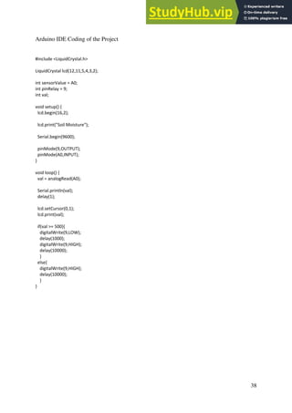
5.0 CONCLUSION
In conclusion, the project meets the objectives. Firstly, the electronics knowledge and
skills are learnt and acquired in a very practical manner. Secondly, the knowledge and
skills of using both the Arduino IDE programming software and the Arduino board
are possessed through the hands-on experience. Lastly, the desired engineering design
process skills are successfully applied and learnt. The project does resolve the
problem statement it is meant to address—to innovate from the daunting problem of
gardening and that is having to water the plant regularly. The project or the system of
the product brings forth the solution to the problem statement by providing an
automated system that performs the watering of plant based on the soil moisture of the
plant. The product constantly runs and measures the soil moisture level and only at a
certain threshold value does the system initiate its watering feature system. All in all,
the project has given the benefit of the opportunity in designing and devising a
product through the engineering design process.
6.0 REFERENCES
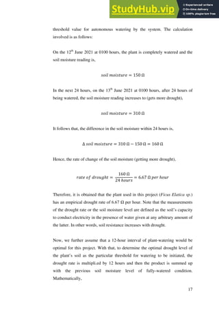
[1] ElectronicsForu. Automated Plant Watering System.
<https://www.electronicsforu.com/electronics-projects/hardware-diy/automatic-plant-
watering-system>
[2] Youtube. Viral Science: Arduino Soil Moisture Sensor Relay Control.
<https://www.youtube.com/watch?v=Ta4eHHiX4-s>
[3] Viral Science. Arduino Soil Moisture Sensor Relay Control.
<https://www.viralsciencecreativity.com/post/arduino-soil-moisture-sensor-relay-
control>
[4] Arduino. Soil Sensor.
<https://www.arduino.cc/reference/en/libraries/soilsensor/>](https://image.slidesharecdn.com/automatedplantwateringsystem-230807154809-63acb520/85/Automated-Plant-Watering-System-pdf-27-320.jpg)
![28
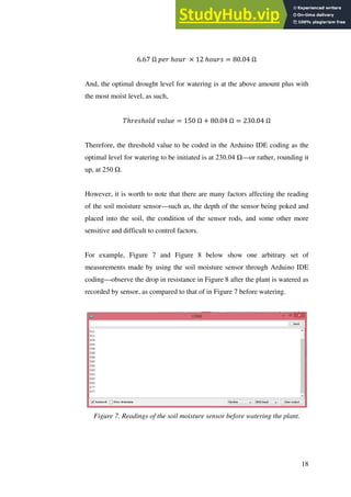
[5] Arduino Project Hub. Automatic Watering System for Plants.
<https://create.arduino.cc/projecthub/lc_lab/automatic-watering-system-for-my-
plants-b73442>
[6] Intructables Circuits. Arduino Soil Moisture Sensor.
<https://www.instructables.com/Arduino-Soil-Moisture-
Sensor/#:~:text=Connect%20the%20two%20pins%20from,m%20interested%20in%2
0Analog%20Data).>
[7] Instructables Circuits. Automatically Water Your Small Indoor Plant Using
Arduino + Pump. <https://www.instructables.com/Automatically-water-your-small-
indoor-plant-using-/>
[8] Youtube. Wojciech Niedbala: Arduino Plant Watering System (Simple).
<https://www.youtube.com/watch?v=Y73twlAdcLs>
[9] Random Nerd Tutorials. Guide for Relay Module with Arduino.
<https://randomnerdtutorials.com/guide-for-relay-module-with-arduino/>
[10] Arduino Project Hub. How To Use A Soil Moisture Sensor.
<https://create.arduino.cc/projecthub/MisterBotBreak/how-to-use-a-soil-moisture-
sensor-ce769b>](https://image.slidesharecdn.com/automatedplantwateringsystem-230807154809-63acb520/85/Automated-Plant-Watering-System-pdf-28-320.jpg)

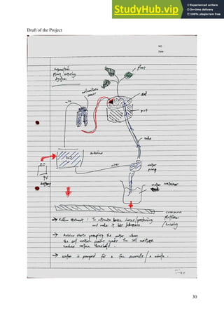
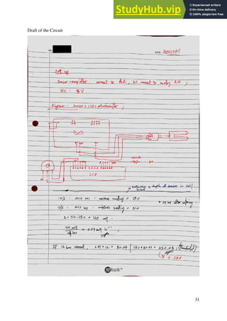
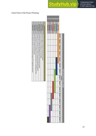


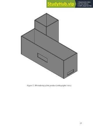
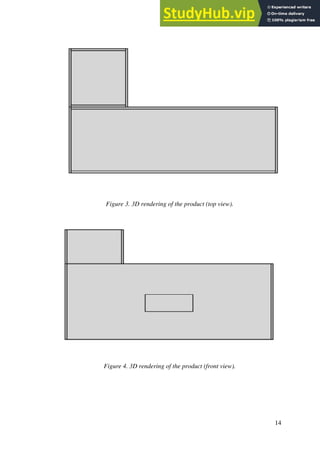
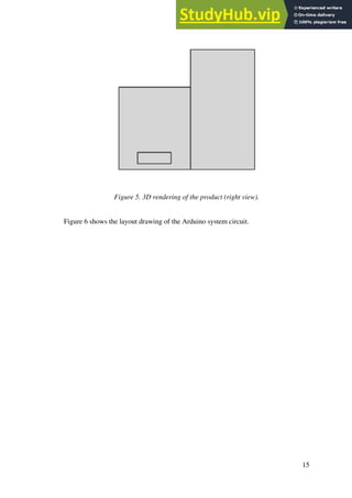
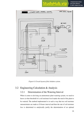
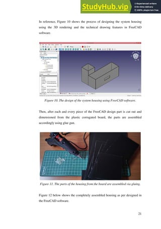
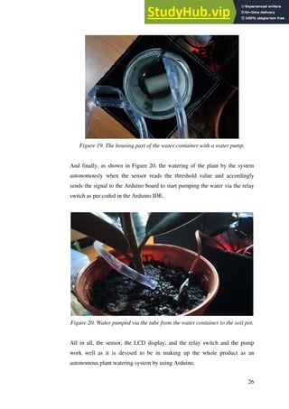
The document summarizes a report for an automatic plant watering system project using Arduino. It includes an introduction that outlines the project objectives, timeline and use of Arduino hardware and software. It then describes the problem statement, design specifications, circuit layout, engineering calculations to determine optimal watering thresholds, and conclusions. The system is programmed to automatically water plants based on soil moisture readings to solve the problem of regular watering needs.