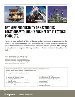
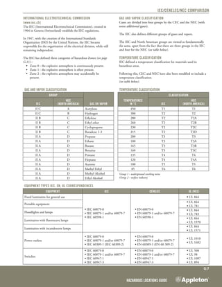
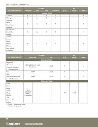
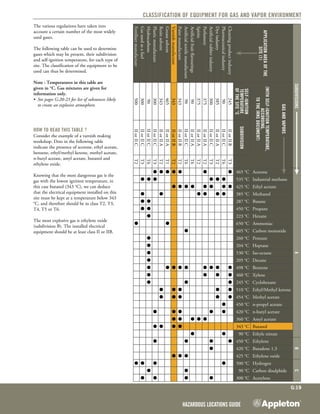
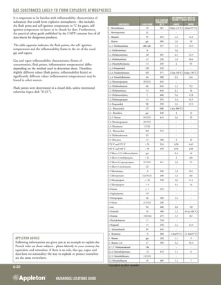
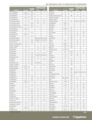
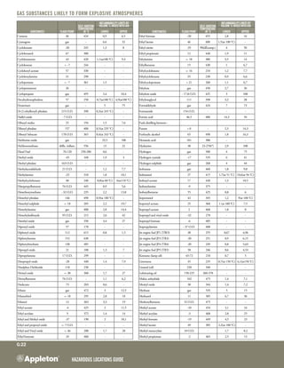
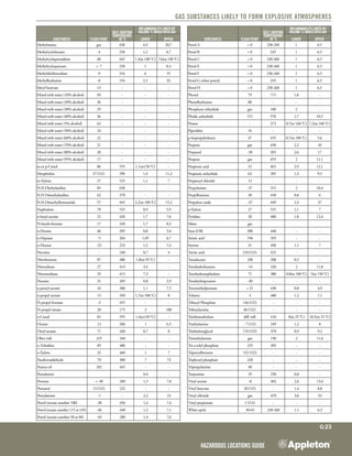
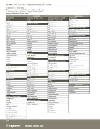
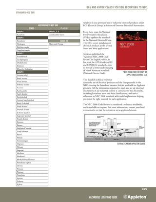
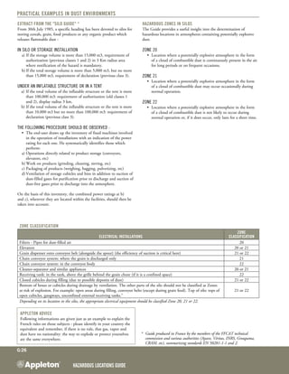
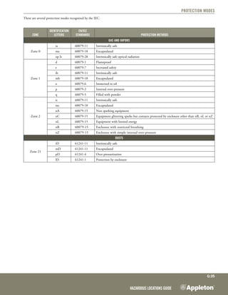
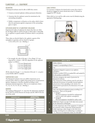
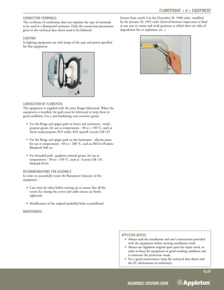
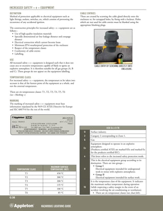
HAZARDOUSLOCATIONSGUIDE
Hazardous Locations Guide
G:1
Table of contents
Introduction	 G:2
Hazardous atmospheres	 G:3-4
Examples of hazardous areas	 G:5
Main international standards 	 G:6
IEC/CENELEC/NEC comparison 	 G:7-8
ATEX European Directives 	 G:9
European Directive 94/9 CE	 G:10
Defining hazardous Areas	 G:11
Defining hazardous Areas for gas and vapors	 G:12-13
Illustration of Gas and Vapor Environment	 G:14-15
Example of French Regulation for Liquid Hydrocarbon Storage	 G:16-17
Selection of equipment for gas and vapor environments	 G:18-19
Gas Substances likely to form Explosive atmospheres	 G:20-23
Gas and vapor Classification according to IEC/Cenelec	 G:24
Gas and vapor Classification according to NEC	 G:25
Practical examples in dust environments	 G:26
Classification of equipment Where Dust is present	 G:27
Dust Which may cause Potentially explosive Atmospheres	 G:28
Classification of dust - general information	 G:29
Selecting equipment in dust environment	 G:30-31
Protection index	 G:32-33
EMC - electromagnetic compatibility	 G:34
Protection modes	 G:35
Flameproof "d" equipment	 G:36-37
Increased safety "e" equipment	 G:38-39
Industrial environment	 G:40
Installation methods throughout the world	 G:41
Selecting cable	 G:42
Installation method for Gable glands	 G:43-46
Installation recommendations	 G:47-49
Appleton Quality control	 G:50-51
Photometry	 G:52
Selection table for Appleton luminaires depending on lamp type	 G:53-54
Inspection and service	 G:55
Mounting Recommendation	 G:56
Request for lighting design	 G:57
Hazardous Locations GUIDE
G:2
Optimize productivity of Hazardous
Locations with highly engineered Electrical
Products.
For over 80 years, Appleton’s ATX line of electrical products has been the international choice for
hazardous and industrial locations. This comprehensive product line is specifically engineered to
the strict requirements these locations demand for safe and efficient operations. Our full range
of cable glands is no exception, delivering confidence to electrical connections throughout your
facility.
Better understanding leads to better choice
Appleton developed the Guide to better inform all persons
involved in explosionproof selection, such as designers,
procurement departments, engineers, site managers, risk or
maintenance managers, authorized bodies controlling the
security on site, distributors' sales forces, etc...
Appleton's advice for installing electrical equipment in areas with explosion risks
Process for installing electrical equipment in areas with explosion risks.
The manager of the installation is solely responsible for :
	 1- 	 Determine hazardous areas.
	 2- 	 Defining Zone boundaries - volumes.
	 3- 	 If necessary, delimiting Zones.
	 4- 	 Knowing the characteristics of flammable substances
			 present on the site.
	 5- 	 Defining the temperature class and the explosion
			 group of the equipment.
	 6- Choosing equipment depending on :
	 	 •	the temperature class and the explosion group,	 	
	 	 •	environmental constraints specific to the site -
			 corrosion, exposure to UV, mechanical strength
	 	 •	protection indexes.
	 7- Installing equipment.
	 8- Commissioning.
	 9- Checking the installation.
Hazardous Locations Guide
G:3
Hazardous Atmospheres
Electrical energy plays an important role in your daily life whether
you are involved in studying, designing or implementing installations.
This energy can become a danger to daily life. This can occur when
energy is used in any industry or warehouse which stores, processes
and manufactures products such as : hydrocarbons, gases, paints,
varnishes, glues, resins, perfumes, cleaning products, rubber, textiles,
plastics, powders, grains, dusts from various origins... There is
thus a high explosion risk with serious consequences for personnel,
equipment and the environment. We talk about an atmosphere with
an explosion hazard.
WHAT CONDITIONS WILL CREATE AN EXPLOSION ?
Three elements are required : 	
	 1- Oxygen in the air. 	
	 2- An inflammable substance, mixed with air. This substance
		 can be :
	 	 •	gas (methane, acetylene), 	
	 	 •	liquid (petrol, solvent), 	
	 	 •	solid (sulphur, wood dust, sugar dust, grains dust...). 	
	 3- 	 An ignition source : 	
	 	 •	with sufficient energy, an electrical arc or a spark,
	 	 •	and/or a rise in temperature.
WHAT IS AN EXPLOSIVE ATMOSPHERE ?
An explosive atmosphere results from a mixture of inflammable
substances in the form of gas, vapors, mist or dust with air in such
proportions that excessive temperature, an electrical arc, spark or any
other energy ignition source produces an explosion.
WHAT IS A POTENTIALLY EXPLOSIVE ATMOSPHERE ?
An atmosphere is defined as potentially explosive when its usual
composition is not explosive, but due to unforeseen circumstances, it
can vary to such an extent that it becomes explosive (the danger exists
as a potential state). Foreseeable circumstances are as follows :
	 • various stages of a manufacturing process, 	
	 • incidents or accidents (rupture of a pipe-line, leak, supply loss),
	 • meteorological conditions (high ambient temperature, air
movements).
WHAT IS MINIMUM IGNITION ENERGY ?
The minimum quantity of energy which must be introduced locally
(in the form of a flame, spark, shock, friction, etc) to cause ignition of
an explosive atmosphere. The majority of industrial ignition sources
contain much higher energy levels than this minimum ignition
energy, which is always low (from tens of microjoules for gas and
vapors to hundreds of millijoules for dusts).
WHAT IS THE SELF-IGNITION TEMPERATURE ?
The self-ignition temperature or spontaneous ignition temperature
is the minimum temperature at which an explosive atmosphere can
spontaneously ignite. The energy required to start a flame can be
changed to thermal form by an increase in the temperature of the
mixture.
WHAT IS THE EXPLOSIVE LIMIT OF AN INFLAMMABLE PRODUCT ?
The ignition of a product depends on its concentration in the air.
It can be produced within a range between two limits :
	 1- lower explosive limit (LEL) of a gas, vapor or dust in the air is
the minimum concentration above which the mixture could
ignite.
	 2- upper explosive limit (UEL) of a gas, vapor or dust is the
maximum concentration under which the mixture could ignite.
WHAT IS THE FLASH POINT OF A LIQUID ?
The flash point is the minimum temperature at which an inflammable
liquid emits sufficient vapors to reach the LEL in the gaseous phase in
equilibrium with the explosive atmosphere.
WHAT TYPES OF SUBSTANCES, GASES, LIQUIDS OR VaporS CAN
PRODUCE AN EXPLOSION ? IN GENERAL, THESE ARE :
	 •	 heating gas, 	
	 •	 hydrocarbons, 	
	 •	 glue and adhesive solvents, 	
	 •	 varnishes and resins, 	
	 •	 manufacturing additives for pharmaceutical products, artificial
dyes, aromas and perfumes, 	
	 •	 manufacturing agents for the following materials : 	 	
plastics, rubbers, man-made textiles and chemical cleaning
products, 	
	 •	 products used in the treatment and manufacturing of alcohols
and derivatives...
> Gas and Vapor Classification : see pages G:24-25.
Dusts Gas and vapors
s12/01/95F s12/01/95F
To produce an explosion, three elements are required simultaneously: oxygen in the air, one or several flammable substances and a
source of ignition.
Hazardous Locations GUIDE
G:4
Hazardous Atmospheres
WHAT TYPES OF DUSTS CAN PRODUCE AN EXPLOSION ?
Organic and metallic products which create powder and dust form
can also in certain conditions become active agents of an explosion.
These are powders and dust of :
	 •	 magnesium, 	
	 •	 aluminium, 	
	 •	 sulphur, 	
	 •	 cellulose, 	
	 •	 corn starch, 	
	 •	 epoxy resins, 	
	 •	 polystyrenes, 	
	 •	 dust of plastic, 	
	 •	 coal, 	
	 •	 wood, 	
	 •	 medick, 	
	 •	 sugar (icing sugar), 	
	 •	 corn (flour)...
> Dust classification : See pages G:28-29.
WHERE MAY EXPLOSIVE ATMOSPHERE FORM ?
Any location where these products are made, stored, and processed
may contain a potentially explosive atmosphere.
> Substances that may form explosive atmospheres : see pages G:21-23.
WHO KNOWS ?
Local authority who delivers operating permits, "bodies" such as
firemen, inspectors from insurance companies are normally aware of
the risks of explosion.
Offshore site
(Appleton lighting fixtures on Total Girassol platform)
Characteristics OF flammable GAS/VaporS Examples
Gas/Vapor
Boiling
temperature Flash point
Self-ignition
temperature
LEL-UEL
(% of the mixture
with air)
Benzene 80 °C -11 °C 498 °C 1,3 - 7,9 %
Ammonia - 33 °C - 33 °C gaz 650 15 - 28 %
Methane - 162 °C - 162 °C gaz 535 5 - 15 %
Butane 2 °C gaz 287 °C 1,8 - 8,4 %
Pentane 36 °C <- 40 °C 260 °C 1,5 - 7,8 %
Octane 126 °C 13 °C 260 °C 1 - 6,5 %
Characteristics OF flammable DUSTS Examples
Dusts
Size of
particles Self-ignition temperature Minimal concentration (9/μ3)
Acetylsalicylic acid 400µ 550 °C 60
Ascorbic acid 39µ 490 °C 60
Paracetamol 120µ –– 30
Extract of rosemary 30µ 380 °C 30
Powder of Valerian 78µ –– 100
Hazardous Locations Guide
G:5
Premises or location
Alcohols (production by distillation)
Batteries (charging workshops)
Acetylene (storage or use of)
Acetylene (manufacture of)
Use or storage of toxic substances or preparation
Acids (use or storage of)
Steeping lighters (deposits of)
Flammable amines, storage
Workshops for repair and servicing of motor vehicles
Wood or similar combustible materials (workshops where these are worked on)
Wood, paper, cardboard or similar combustible materials (deposits of)
Candles or other wax objects, etc. (moulding of)
Grinding, crushing, etc., of vegetable substances and all organic products
Polymer processing
Easily flammable solids
Charcoal (deposits or warehouses of)
Heating (processes)
Shoes or leather/skin products (manufacture of)
Oxidising substances (manufacture, use, storage of)
Detergent (manufacture of products)
Fibres of vegetable or animal origin, artificial or synthetic fibres (processing of)
Fruit or vegetables (ripening, degreening, whitening, disinfestation rooms)
Gasometers and compressed gas tanks
Liquefied fuel gases (filling stations, or distribution of)
Tar, pitch, resins, etc. (mixture or hot processing of)
Coal, coke, etc (warehouses and deposits of)
Vegetable oils (extraction of)
Gaseous hydrogen (storage, use of)
Flammable liquids (storage and manufactured tank of)
Flammable liquids (installations for blending, processing or use of)
Flammable liquids (filling or distribution stations)
Leather goods (workshops)
Plastics, plastomers or elastomers (manufacture of)
Ammonium nitrate (deposits of)
Blended ammonium nitrate (deposits of)
Processing of vegetable fibres
Liquid oxygen (deposits of)
Covered car parks
Organic peroxides (use, manufacture, storage of)
Refrigeration or compression (installations)
Sugar factories, sugar refineries, malt houses
Silos and storage installations for cereals, grain, food products or any organic products releasing flammable dust
Textile dyeing and printing
Fabrics, knitted articles, tulles, guipure lace, etc (manufacturing workshops)
Varnishes, paints, primers, glues, rendering (application, baking, drying of)
Following informations are given just as an example to explain the
French rules on those subjects : please identify in your country the
equivalent and remember, if there is no rule, that gas, vapor and dust
have no nationality : the way to explode or protect yourselves are the
same everywhere.
Using the description for installations classified for protection of the
environment in France, in accordance with the decree of May 20,
1953, modified on December 28, 1999.
Non-exhaustive list extracted from the typical orders for which
installations requiring a declaration should satisfy the provisions of the
ministerial order of March 31, 1980. 
Decree relating to electrical installations in establishments regulated
under the legislation governing installations classified as likely to
present a risk of explosion.
Many countries produce similar documents.
Hazardous Locations GUIDE
G:6
Main standards throughout the world
NEC mandatory
ATEX/CENELEC members
ATEX/CENELEC affiliates
A number of admissible standards
(IEC, CENELEC, NEC, others)
CEC mandatory
The worldwide electrotechnical standard for electrical equipment for
explosive atmospheres is covered by two major "standards" :
	 1- 	IEC/ATEX/CENELEC (common standard following agreement
in 1991 on procedures for developing standards)
		 IEC : International Electrotechnical Commission
ATEX : ATmospheres EXplosibles
	 	 CENELEC : European Committee of Electrotechnical
		 Standards
	 2- 	NEC, CEC (products approved by UL, FM, CSA...).
		 NEC : National Electrical Code
		 CEC : Canadian Electrical Code
Products which conform to IEC/ATEX/CENELEC or NEC
standards have identical protection, even though they are designed
differently to meet specific installation regulations.
IEC can be considered as the "international standard" accepted in
nearly every country.
Since 1996, NEC, Article 505, uses the IEC names of gas groups,
equipment temperature classes and area definitions.
> To obtain more detailed information, contact the national
laboratories : LCIE, INERIS , PTB, DEMKO, CSA, UL, KEMA,
DNV, LOM.....
IECEx
The aim of the IECEx Scheme is to facilitate international trade in
electrical equipment intended for use in explosive atmospheres (Ex
equipment) by eliminating the need for multiple national certification
while preserving an appropriate level of safety.
The IEC Ex Scheme provides the means for manufacturers of EX
equipment to obtain certificates of conformity that will be accepted at
national level in all participating countries. A certificate of conformity
may be obtained from any certification body accepted in the Scheme.
The certificate will attest that the equipment design conforms to
the relevant IEC standards and that the product is manufactured
under a quality plan assessed by an Accepted Certification Body.
Manufacturers holding certificates of conformity may affix the
IECEx Mark of Conformity to equipment that thy have verified as
complying with the certified design.
An application for a country to participate in the IECEx Scheme is
made on a standard by standard basis by the candidate Member Body
of the IECEx Scheme for that country. The application is made to the
Secretary of the Ex Management Committee. There are currently 17
Accepted Certification Bodies (ACBs) in 22 countries participating in
the IECEx Scheme.
Hazardous Locations Guide
G:7
IEC/CENELEC/NEC Comparison
International electrotechnical Commission
(www.iec.ch)
The IEC (International Electrotechnical Commission), created in
1904 in Geneva (Switzerland) establish the IEC regulations.
In 1947, with the creation of the International Standards
Organization (ISO) by the United Nations, the IEC became
responsible for the organization of the electrical division, while still
remaining independent.
The IEC has defined three categories of hazardous Zones (see page
G:11) :
	 •	 Zone 0 : the explosive atmosphere is continuously present.
	 •	 Zone 1 : the explosive atmosphere is often present.
	 •	 Zone 2 : the explosive atmosphere may accidentally be
		 present.
Gas and vapor classification
Gases are divided into four groups by the CEC and the NEC (with
some additional gases).
The IEC also defines different groups of gases and vapors.
The IEC and North American groups are viewed as fundamentally
the same, apart from the fact that there are three groups in the IEC
and four for the NEC (see table below).
Temperature classification
IEC defined a temperature classification for materials used in
hazardous areas.
Following this, CEC and NEC have also been modified to include a
temperature classification.
(see table below).
Gas and Vapor CLASSIFICATION TEMPERATURE CLASSIFICATION
Group
Gas or Vapor
Temperatures
IN °C
Classification
IEC
NEC
(North America) IEC
NEC
(North America)
II C A Acetylene 450 T1 T1
II C B Hydrogen 300 T2 T2
II B C Ethylene 280 T2 T2A
II B C Ethyl ether 260 T2 T2B
II B C Cyclopropane 230 T2 T2C
II B C Butadene 1-3 215 T2 T2D
II A D Propane 200 T3 T3
II A D Ethane 180 T3 T3A
II A D Butane 165 T3 T3B
II A D Benzéne 160 T3 T3C
II A D Pentane 135 T4 T4
II A D Heptane 120 T4 T4A
II A D Acetone 100 T5 T5
II A D Methyl Ethyl 85 T6 T6
II A D Methyl Alcohol Group 1 - underground working mine
Group 2 - surface industryII A D Ethyl Alcohol
Equipment types IEC, EN, UL correspondences
Equipment IEC CENELEC UL (NEC)
Fixed luminaires for general use
• IEC 60079-0
• IEC 60079-1 and/or 60079-7
• IEC 60598-1
• EN 60079-0
• EN 60079-1 and/or 60079-7
• EN 60598-1
• UL 844
Portable equipment
• UL 844
• UL 781
Floodlights and lamps
• UL 844
• UL 783
Luminaires with fluorescent lamps
• UL 844
• UL 1570
Luminaires with incandescent lamps
• UL 844
• UL 1571
Power outlets
• IEC 60079-0
• IEC 60079-1 and/or 60079-7
• IEC 60309-1 (IEC 60309-2)
• EN 60079-0
• EN 60079-1 and/or 60079-7
• EN 60309-1 (EN 60 309-2)
• UL 1010
• UL 1682
Switches
• IEC 60079-0
• IEC 60079-1 and/or 60079-7
• IEC 60947-1
• IEC 60947-3
• EN 60079-0
• EN 60079-1 and/or 60079-7
• EN 60947-1
• EN 60947-3
• UL 508
• UL 98
• UL 1087
• UL 894
Hazardous Locations GUIDE
G:8
IEC/CENELEC/NEC Comparison
Inflammable Material
IEC/CENELEC NEC
Protection Zone Group Subdivision Class Division Group
Gases and vapors
Acetylene d - e 1,2 II C I 1 - 2 A
Hydrogen d - e 1,2 II C I 1 - 2 B
Propylene
d - e 1,2 II B I 1 - 2 B
Oxide
Ethyl oxide
Butadiene
Cyclopropane
d - e 1,2 II B I 1 - 2 CEthyl Ether
Ethylene
Acetone
d - e 1,2 II A I 1 - 2 D
Benzene
Butane
Propane
Hexane
Paint Solvents
Natural Gas
Inflammable Material
IEC/CENELEC NEC
Protection Zone Class Division Group
Combustible Dusts
Magnesium
IEC / CENELEC / NEC
Comparison
21-22 II 1 E
Aluminium
or metallic dusts with
R ≤ 105 Ohms x cm
Coal D/DIP 21-22 II 1 F
Floor
D/DIP 21-22 II 2 GNon metallic dusts with
R > 105 Ohms x cm
Fibers and Flyings
Rayon
IEC /
CENELEC
/ NEC
Comparison
III 1 - 2(1)
Cotton
Linen
Wood
Hemp
Flax bast
Tow
Coconut fiber
Oakum
(1) Division 1 : manufacturing location
Division 2 : storage location
Hazardous Locations Guide
G:9
ATEX European Directives
Two European Directives
On July 1, 2003, two important European directives concerning
electrical equipment for potentially explosive atmospheres, introducing
part of the new approach, came into force :
•	 Directive 94/9 CE concerns more specifically manufacturers who
are obliged to offer their customers ATEX products from June
30, 2003 onwards.
•	 Directive 99/92 CE concerns all users (specifiers, investors,
contractors, OEMs or distributors) of equipment for potentially
explosive atmospheres.
Both of these result from articles 100 A and 118 A of the Treaty of
Rome (1957).
1- Directive 94/9 EC
Directive 94/9 EC defines the minimum requirements aimed at
improving protection, in terms of health and safety, for workers likely
to be exposed to risks of potentially explosive atmospheres.
It also defines the equipment capable of ensuring the desired safety
and the resources to be employed in selecting, installing, using and
maintaining this equipment.
This specifies safety requirements for both electrical and non-electrical
equipment, designed for use in hazardous locations as a result of the
presence of gas or dust.
As of July 1, 2003, all electrical equipment for potentially explosive
atmospheres sold within the European area must have ATEX
certification, as a result, they must bear the standard ATEX marking
on the product certification plate, in accordance with the new
European classification of products.
2- Directive 99/92 EC
From July 1, 2003, it is mandatory to comply with the minimum
safety regulations described in the directives which need to be followed
routinely in hazardous locations.
The obligations on the employer or site manager are mainly :
•	 risks of explosion analysis; identification, assessment and record
keeping (article 8),
•	 classification of hazardous areas (or Zones),
•	 training of workers,
•	 validation of the conformity of the installation,
•	 procedure for maintenance of the installation,
•	 procdure in case of Alert and Evaluation.
ATEX/CENELEC members
ATEX/CENELEC affiliates
EU neighbouring countries
Hazardous Locations GUIDE
G:10
ATEX equipment classification
Directive 94/9 CE defines a new of hazardous Zones, with a
distinction between gas (G) or dust (D) atmospheres. As a result,
it introduces the existence of Zones 20, 21 and 22 corresponding
to dust environments and the concept of categories 1, 2 and 3 for
equipment.
ATEX product marking
As of July 1, 2003, all electrical equipment for potentially explosive
atmospheres sold within the European area must have "ATEX"
certification and, as a result, bear the standard ATEX marking
on the product nameplate, in accordance with the new European
product classification.
ATEX classification
Zones 0 20 1 21 2 22
Type of atmosphere G D G D G D
Potentially explosive atmosphere Continuous presence Intermittent presence Occasional presence
Equipment category 1 2 3
CHARACTERISTICS of PRODUCT MARKINGS (FOR exAmple, FLUORESCENT CAT. NO FEB236BUSN)
Environment Gas Dust
Marking 0081 II2G 0081 II2D
ATEX/IEC marking Ex de IIC Ex tD A 21 T 75 °C
Temperature class T4 or T5
EC type-examination certificate LCIE 07 ATEX 6017
IEC certificate IECEx LCI 04.0017
Ambient temperature -40°C≤ Ta ≤ 55 °C
Protection index IP66/67 / IK10
Examples of marking
Label for "e" fluorescent lamp Cat. No. FEB236BUSN
	 Type FLe	 FEB236BUSN
	       	 (091655) - (096555)
Amiens - FRANCE	 LCIE 07 ATEX 6017	 -40°C≤ Ta ≤ +55°C
0081 II 2 GD	 Ex de IIC T4 - Ex tD A21    IP66/67	 T = 75 °C
	 IECEx LCI 04.0017   imax=0.65A	
	 E.O.L	 110 / 254V +/-10% 0-50-60Hz G13/Fa6             T5 (-40°C≤ Ta ≤ +40°C)
	 Approved	 Avertissement - Warning
		 Apres MISe hors tension, attendre 60 minutes avant l'ouverture
	 	 (Uniquement pour Zone poussière)
	
IK10
	 After de-energizing, Wait 60 minutes before opening
	 	 (only for dust areas)
F
Hazardous Locations Guide
G:11
Defining Hazardous areas
What is said in official texts ?
The IEC international regulation (standard IEC/EN 60079/10)
makes a distinction between the following hazardous Zones :
	 •	 Zone 0,
	 •	 Zone 1,
	 •	 Zone 2.
Three types of Zone
Since July 1, 2003, with the new Directives ATEX, there are three
types of Zone :
	 •	 Zone 0 - 20,
	 •	 Zone 1 - 21,
	 •	 Zone 2 - 22.
Zone 0 - 20
Zone in which an explosive mixture of gas, vapor or dust is
continuously present (the gaseous phase inside a receptacle or a
closed-off chamber constitutes a Zone "0").
Zone 1 - 21
Zone in which an explosive mixture of gas, vapor or dust is likely to
occur during normal operation.
Zone 2 - 22
Zone in which an explosive mixture is not likely to occur in normal
operation, and if it occurs will only exist for a short time (leaks or
negligent use).
Frontiers between Zones
These Zones are geographic, but the frontiers between them are
never precisely determined, because a Zone can move for several
reasons : product warm-up, faulty ventilation of the room, climate
variations, handling mistake, air movement.
The THREE TYPES OF ZONE
Continuous danger
Potential danger
Accidental danger
GAS & VAPOURS
DUST
22
21
20
0
1
2
EX
Hazardous Locations GUIDE
G:12
Defining Hazardous areas for Gas and Vapors
How to determine the Zones ?
The plant manager or his employees, controlled by external accredited
advisers, are the only people authorized to determine hazardous areas
in a location where gas and vapor are present.
To determine these Zones, 4 essential questions have to be solved.
1- What is the emission level of my release source ?
These are the emission points of inflammable substances into the
atmosphere. 
Three levels of release source can be distinguished :
	 1- Continuous emission level.
		 The release source is the surface of an inflammable liquid :
	 	 	 •	 In an enclosed receptacle,
	 	 	 •	 In an open receptacle,
	 	 	 •	 Inside enclosed manufacturing or mixing equipment.
	 2- First level emission.
	 Release during normal operation. The main release sources
		 are the following :
	 	 	 •	 Open manufacturing or mixing equipment,
	 	 	 •	 Vents on enclosed receptacles,
	 	 	 •	 Hydraulic guard venting holes,
	 	 	 •	 Extremities of articulated loading arms for tankers and
				 containers,
	 	 	 •	 Apparatus loading bungs and emptying valves,
	 	 	 •	 Sampling and venting valves,
	 	 	 •	 Pump and compressor gaskets, where leaks persist
	 	 	 	 (example: cable gland operating leaks),
	 	 	 •	 Non-watertight switches and conduits.
	 2- Second level emission.
	 Release during abnormal operation. The main release sources
		 are the following :
	 	 	 •	 Flanges, connections, vents and pipe joints,
	 	 	 •	 Glass inspection holes or level indicators,
	 	 	 •	 Gaskets in pumps or compressors, designed to prevent leaks,
	 	 	 •	 Fragile apparatus such as glass, ceramic, graphite, etc...,
	 	 	 •	 Breathing holes in pressure reduction valve membranes,
	 	 	 •	 Retaining sumps.
2- What type of opening do I have ?
All openings (doors, windows, ventilation outlets, etc) between two
geographical locations should be considered as possible release sources. 
The release level depends on the following :
	 •	 The type of Zone of the adjoining geographical area,
	 •	 The frequency and duration of opening,
	 •	 The pressure difference between the geographical areas,
	 •	 The effectiveness of the gaskets or joints.
There are 4 types of opening :
	 1- Type A openings.
	 	 	 •	 Open passages : conduits, piping through walls, ceilings
				 and floors,
	 	 	 •	 Fixed ventilation outlets installed in rooms and buildings,
				 opened frequently or for long periods.
	 2- Type B openings.
	 	 	 •	 Normally closed (example : automatic closing), rarely open,
				 and difficult to adjust.
	 3- Type C openings.
	 	 	 •	 Type B openings, with watertightness in addition to that,
				 equipped with independent automatic closing,
	 	 	 •	 Two type B opening in series.
	 4- type D openings.
	 	 	 •	 Can only be opened using a special device or in an
				 emergency,
	 	 	 •	 Completely weatherproof openings,
	 	 	 •	 Combination of a type B and a type C opening, in series
	 	 	 	 (joined together).
3- What is the ventilation availability ?
The efficiency of ventilation in dispersing or maintaining the explosive
atmosphere depends on its quality and level, as well as its design. An
artificial ventilation system is therefore :
Very good
	 •	 Operates almost continuously and therefore backed up.
Good
	 •	 Operated while the site is operating.
Poor
	 •	 Does not operate continuously or during normal site operation,
		 it operates without any interruption for long periods.
4- What level is the ventilation ?
Evaluation of the ventilation level requires a knowledge of the
maximum gas or vapor release rate at the release source, either by
controlled tests, by calculation, or by established hypotheses. There are
three levels of ventilation :
High
	 •	 Ventilation reduces the concentration at the release source and
	 	 reduces it to a level below the LEL value (lower explosive limit).
Average
	 •	 Ventilation controls the concentration, leading to a stable
		 situation.
Weak
	 •	 Ventilation cannot control the concentration during release
	 	 and/or cannot prevent the explosive atmosphere continuing
		 after release is over.
Appleton advice for designing a ventilation system
Here are the important points to remember for designing a
ventilation system * :
•	 Air for ventilation should be taken from a non hazardous area.
•	 Artificial ventilation should be controlled and monitored.
•	 As gases and vapors often have different densities to that of
air, they have a tendency to accumulate where air movement is
likely to be reduced.
•	 Obstacles can reduce the movement of air. Therefore the
« topography » of geographical locations should be taken into
account (inside and/or outside).
* See standards IEC 60079-10.
Hazardous Locations Guide
G:13
Defining Hazardous areas for Gas and Vapors
SUMMARY TABLE FOR GAS AND VaporS
The table below corresponds to IEC standard 60079-10 which can determine the type of Zone according to three criteria :
the release emission level, the ventilation level and the ventilation availability.
Release
emission
level
Ventilation level
Weak Average High
Ventilation availability
Good or
Very Good Poor
Poor
Good Very Good Poor Good Very Good
Continuous Zone 0
Zone 0 Zone 0
Zone 0 Zone 1 Zone 2
Zone 0 (NE)*
Zone 1 Zone 2 Non-hazardous
First
Zone 0 Zone 1 Zone 1
Zone 1 Zone 2 Zone 2
Zone 1 (NE)*
Zone 1 Zone 2 Zone 2 Non-hazardous
Second
Zone 0
Zone 2 Zone 2 Zone 2 Zone 2 Non-hazardous
Zone 2 (NE)*
Zone 1 Non-hazardous
Zones in which "e" increased safety (page G:38) or flameproof "d" (page G:36) material can be installed.
* NE = negligible extent
DOWNSTREAM EFFECT ON THE DEGREE OF RELEASE OF THE OPENING
Probable Zones in
upstream of the opening
Types of openings
A B C D
Zone 0 Continuous
(Continuous)
First
Second No release
Zone 1 First
(First)
Second
(Second)
No release
No release
Zone 2 Second
(Second)
No release
No release No release
Note : for the release emission levels between parenthesis, it is advised to consider the opening frequency of the doors when at the design stage.
Continuous emission release usually leads
to classification as Zone 0
First level emission release usually leads
to classification as Zone 1
Second level emission usually leads
to classification as Zone 2
Appleton advice for installing electrical equipment in areas with explosion risks
Process for installing electrical equipment in areas with explosion risks.
The manager of the installation is solely responsible for :
	 1- 	 Determine hazardous areas.
	 2- 	 Defining Zone boundaries - volumes.
	 3- 	 If necessary, delimiting Zones.
	 4- 	 Knowing the characteristics of flammable substances 	present 	
			 on the site.
	 5- 	 Defining the temperature class and the explosion
			 group of the equipment.
	 6- Choosing equipment depending on :
	 	 •	the temperature class and the explosion group,	 	
	 	 •	environmental constraints specific to the site - corrosion,
			 exposure to UV, mechanical strength,
	 	 •	protection indexes.
	 7- Installing equipment.
	 8- Commissioning.
	 9- Checking the installation.
Hazardous Locations GUIDE
G:14
Illustration of gas and vapor environment
Modifications of Zones related to appropriate equipment
s35/01/95F
Example 1
•	 The mixing tank is in the open air.
•	 The room is not ventilated mechanically.
•	 The products are always present in the
	 workshop.
•	 All operations are manual.
Ho
Storage
s35/02/95F
Example 2
•	 A hood has been fitted above the tank.
•	 The room is ventilated.
•	 The products in stock are separated from
	 the rest of the workshop.
•	 Part of the work is manual.
s35/03/95F
Control
console
Solenoid
Valves
Example 3
•	 The tank is closed off.
•	 The room is ventilated mechanically
•	 The products are stored outside. 
•	 All operations are controlled via a console
outside the Zone.
— The only risk that remains is when tank is
opened for inspection or maintenance.
Hazardous Locations Guide
G:15
Compulsory protection measures
The risk of explosion must be safe guarded by the concurrent use of
specific protection measures :
	 •	 Internal overpressure in the room,
	 •	 Continuous dilution,
	 •	 Intake at the source.
The latter two measures are only possible when the maximum
discharge flow is known accurately.
Measures must be taken to compensate for a possible failure in the
particular measures used :
	 •	 Light and/or sound alarm,
	 •	 Measures necessary to repair and restart the protection device as 	
		 quickly as possible,
	 •	 Automatic power off device controlled by :
		 –	 A tester that checks that overpressure, dilution or ventilation 	
			 devices are working correctly,
	 	 –	 Or an atmosphere tester (fixed explosion meter with 	 	
	 	 	 continuous operation) that switches power off at a control	
	 	 	 threshold set to 25% of the LEL (lower explosive limit) if 	
	 	 	 no personnel are present and 10% of the LEL if there are 	
			 personnel present.
Typical guide for liquid hydrocarbon storage
Tanker truck unloading station.
3
m
s40/02/95F
Mobile tank filling device
s40/03/95F
3 m
3m
Appleton advice
The additional measures are difficult and expensive, so that Zone 1
equipment is frequently used over entire sites.
This equipment covers explosion risks at all times, regardless of
uncontrollable environmental variations.
This position was adapted by same significant oil companies.
Zone 0 Zone 1 Zone 2 Non-Hazardous Zone
Definition of Zones : see page G13.
Hazardous Locations GUIDE
G:16
Example of French regulation for liquid hydrocarbon storage
Before protection Before protection Before protection
s36/01/95F s36/03/95F s36/01/95F
after protection after protection after protection
s36/02/95F
Pump
Solvants
s36/04/95F
Solvants
s36/06/95F
Inert
Gas
The workshop classified as Zone 1 becomes
Zone 2 by installing a closed circuit
process : using a closed tank supplying
reagents and emptying the finished product
via piping.
The control station of a workshop
classified as Zone 1 can be derated to Zone
2 by installing an over-pressure cubicle.
The workshop becomes Zone 2 by
introducing an inert gas which prevents the
formation of an explosive atmosphere.
Protection by closed circuit
operation
When this method can be used it is the safest
way to limit risks. The explosive atmosphere
is confined to the interior
of one or several storage receptacles.
The electrical equipment can easily be
installed outside.
Protection by over-pressure
The entry of inflammable gases or vapors into
an enclosure containing ordinary electrical
equipment or any other ignition source, is
prevented by maintaining, in this enclosure,
a gas pressure (usually air) higher than the
pressure outside (e.g. in the control room).
Over-pressure may be static after the initial
sweep, the apertures in the enclosure are
closed and the air flow provides simple
counteraction to natural leaks.
Over-pressure may also be of a dynamic
nature : an air-flow is deliberately created
across apertures of a chosen cross-section.
Protection by inert gas
By adding an inert gas, the oxygen content
of the air in an enclosure is reduced to
such a weak value that the atmosphere
would no longer be explosive, whatever the
concentration of inflammable gases and
vapors.
The inert gas generally used is nitrogen, but
carbon dioxide is used on some occasions.
Hazardous Locations Guide
G:17
Example of French regulation for liquid hydrocarbon storage
Before protection Before protection Protection by under-pressure
s36/01/95F s37/03/95F
Closed drums of solvants
The diffusion of inflammable gases or vapors
outside an enclosure is prevented by the
maintenance therein of a pressure lower than
that of the surrounding Zone.
The surrounding Zone, which is not
hazardous, can also contain without risk
conventional electrical equipment or any
other inflammable sources.
after protection after protection Protection by continuous dilution
s37/02/95F
s37/04/95F
Closed drums of solvants
The inflammable gas and vapor content is
reduced to a value below that of the lower
explosive limit(1) by adding a protective gas
which is continuously fed into the required
Zone. The protective gas is, in general, air.
* Switch-off threshold set at 25% of the LEL. if
personnel are absent and at 10% if personnel
are present.
A Zone 1 classified workshop becomes Zone
1 (in part) and Zone 2 (for the remainder) by
installing a suction device at source.
A Zone 2 classified warehouse can become
a non hazardous Zone by installing a very
good quality general forced ventilation
system.
Protection by suction at source
The creation of a localized depression by
means of ducting diverts the inflammable
gases and vapors to a Zone carrying no risk of
explosion when in operation.
This type of protection is essentially used
in workshops where there are few discharge
points.
Inside the suction Zone safety type electrical
equipment should be used.
Protection by general suction
The inflammable gas and vapor content is
maintained at a level below that of the lower
explosive limit in a large Zone by a general
suction device.
This type of protection is very delicate to
operate because hazardous concentrations
of inflammable gases and vapors generally
remain at their point of discharge and in dead
Zones.
Appleton advice
What should be done in order to prevent if possible failure in one of the
types of protection ?
These types of protection use equipment that is often very
complex (inerting, over-pressure, suction devices, etc), which could
malfunction. If a malfunction occurs, the room reverts to its initial
classification.
It is therefore necessary, for each device, to define additional safety
measures to be taken, to guarantee, in the event of failure, the safety
of workers.
For example : the disruption of energy sources (such as electricity,
water, inert gas, etc) can cause a failure in the mode of protection.
It is therefore necessary to study the room from the start, to provide
for built-in backup energy circuits to ensure total safety.
Zone 0 Zone 1 Zone 2 Non-Hazardous Zone
Definition of Zones : see page G:11.
Hazardous Locations GUIDE
G:18
Which Temperature Group SHOULD BE CHOSEN ?
According to the spontaneous ignition temperature of the gases, this
table indicates the temperature class of the equipment which can be
used (see page G:20-23).
	 •	 The temperature class of the equipment must always be
		 lower than the spontaneous ignition temperature of the
		 gases.
	 •	 Equipment must never be used in an atmosphere capable
		 of ignition at the temperature indicated on the marking
	 	 (temperature class).
Temperature class of the equipment
Spontaneous ignition
temperature of the gases (T°)
Temperature class of the equipment
T6
(85°)
T5
(100°)
T4
(135°)
T3
(200°)
T2
(300°)
T1
(450°)
85°≤ T° ≤100 °C
100° < T° ≤ 135 °C
135° < T°≤ 200 °C
200° < T°≤ 300 °C
300° < T° ≤ 450 °C
450 °C < T°
Danger : explosion Equipment which can be used.
Acetaldehyde spontaneous ignition temperature 175 °C Class of equipment which can be used : T4, T5 or T6.
Criteria of Selection of Equipment
The criteria of selection are the following :
	 •	  Gas and vapors classification,
	 •	  Protection indexes,
	 •	  Protection modes,
	 •	  Industrial environment (corrosion).
The table below indicate the equipment groups which can be used
depending on the gas and vapor subdivision.
Which EQUIPMENT GROUP SHOULD BE CHOSEN ?
This table indicates the equipment groups which can be used
depending on the gas and vapor classification (see page G:19).
A distinction is made between two groups of electrical equipment :
Group I
	 •	 Electrical equipment intended for underground work in
		 mines with explosive atmospheres.
Group II
	 •	 Electrical equipment designed for surface industry.
Electrical equipment which can be used
Gas/Vapor
subdivision
Equipment groups which can be used
Increased safety
"e"
Flameproof
"d"
Associated Protection modes
"d" + "e"
A II IIA - IIB - IIC IIA - IIB - IIC
B II IIB - IIC IIB - IIC
C II IIC IIC
Hazardous Locations Guide
G:19
Classification of Equipment for gas and vapor environment
The various regulations have taken into
account a certain number of the most widely
used gases.
The following table can be used to determine
gases which may be present, their subdivision
and self-ignition temperature, for each type of
site. The classification of the equipment to be
used can thus be determined.
Note : Temperatures in this table are
given in °C. Gas mixtures are given for
information only.
•	 See pages G:20-23 for list of substances likely
to create an explosive atmosphere.
How to read this table ?
Consider the example of a varnish making
workshop. Dots in the following table
indicate the presence of acetone, ethyl acetate,
benzene, ethyl/methyl ketone, methyl acetate,
n-butyl acetate, amyl acetate, butanol and
ethylene oxide.
Knowing that the most dangerous gas is the
gas with the lowest ignition temperature, in
this case butanol (343 °C), we can deduce
that the electrical equipment installed on this
site must be kept at a temperature below 343
°C, and therefore should be in class T2, T3,
T4, T5 or T6.
The most explosive gas is ethylene oxide
(subdivision B). The installed electrical
equipment should be at least class II or IIB.
SubdivisionsABC
ApplicationAREAOFTHE
SITE (1)
GASANDVaporS
Acetone
Industrial methane
Ethyl acetate
Methanol
Butane
Propane
Hexane
Ammoniac
Carbon monoxide
Pentane
Heptane
Iso-octane
Decane
Benzene
Xylene
Cyclohexane
Ethyl/Methyl ketone
Methyl acetate
n-propyl acetate
n-butyl acetate
Amyl acetate
Butanol
Ethyle nitrate
Ethylene
Butadene 1.3
Ethylene oxide
Hydrogen
Carbon disulphide
Acetylene
(withself-ignitiontemperature,
according,
totheIRNSdocument)
Self-ignition
temperature
ofthesite°C
Subdivision
465 °C
535 °C
425 °C
385 °C
287 °C
450 °C
223 °C
650 °C
605 °C
260 °C
204 °C
530 °C
205 °C
498 °C
460 °C
245 °C
510 °C
454 °C
450 °C
420 °C
360 °C
343 °C
90 °C
450 °C
420 °C
425 °C
500 °C
90 °C
300 °C
Cleaningproductindustry245IIorII BT3llllllll
Pharmaceuticalindustry90IIorII CT6lllllll
Dyeindustry385IIorII AT2llllll
Artificialrubberindustry300IIorII CT3lllllll
Perfumery375IIorII AT2llllll
Spirits375IIorII AT2ll
Artificialfruitflavourings90IIorII AT6lll
Artificialtextilemanufacture90IIorII CT6llllllll
Paintmanufacture343IIorII BT2lllllllll
Varnishmanufacture343IIorII BT2lllllllll
Greasesolvent465IIorII AT1lll
Resinsolvent343IIorII AT2lllll
Plasticmanufacture300IIorII CT3lllllll
Hydrocarbons90IIorII CT6llllllllllll
Gasusedasafuel300IIorII CT3llllll
Fertilisermanufacture500IIorII CT2ll
Hazardous Locations GUIDE
G:20
Gas substances likely to form explosive atmospheres
Classified on first number
Substances Flash point
Self-ignition
temperature
in °C
Inflammability limits by
volume % mixed with air
Lower Upper
1 - Bromobutane 18 265 0,6(at 111 °C) 5,8(at155 °C)
1 - Bromopentane 32 - - -
1 - Butanol 29 343 1,4 11,2
1 - Butene gaz 380 1,6 10
1,1,1-Trichloroethane diff. infl. 537 7,5 12,5
1,1-Dichloroethane -6 - 5,6 -
1,1-Dichloroethylene -28 565 6,5 15,5
1,1-Diethoxyethane -21 230 1,6 10,4
1,1-Dimethylhydrazine -15 249 2 95
1,2,3-Propanetriol 199 370 - -
1,2,4-Trichlorobenzene 105 571 2,5(at 150 °C) 6,6(at 150 °C)
1,2,4-Trimethylbenzene 44 500 0,9 6,4
1,2-Diaminopropane 33 O.D. 416 - -
1,2-Dichlorobenzene 66 645 2,2 9,2
1,2-Dichloroethane 13 410 6,2 16
1,2-Dichloroethylene 2 460 5,6 12,8
1,2-Dichloropropane 15 555 3,4 14,5
1,2-Propanediol 98 370 2,6 12,5
1,3 - Benzenediol 127 608 1,4(at 200 °C) -
1,3 - Butadiene gaz 420 2 12
1,3,5-Trioxan 45 O.D. 414 3,6 29
1,3-Diaminopropane 24 O.D. - - -
1,3-Dioxolanne 1 O.D. - - -
1,4 - Benzenediol 165 515 - -
1,4-Dichlorobenzene 65 - - -
1,4-Dioxanne 12 180 2 22
175 °C and 275 °C > 70 254 0,58 4,45
185 °C and 330 °C > 70 259 0,52 4,09
1-Chloro-1,2,2-trifluoroethylene gaz - 8,4 16
1-Chloro-2 methylpropane < 21 - 2 8,8
1-Chloro-2,3-epoxypropane 31 O.D. 411 3,8 21
1-Chloro-4 nitrobenzene 127 - - -
1-Chlorobutane -9 240 1,8 10,1
1-Chloropentane 12,8 O.D. 260 1,6 8,6
1-Chloropropane <- 18 520 2,6 11,1
1-Chloropropene <- 6 - 4,5 16
1-Hexene <- 7 253 - -
1-Naphtylamine 157 - - -
1-Nitropropane 36 420 2,2 -
1-Octene 21 O.D. 230 - -
1-one 84 460 0,8 3,8
1-Pentanol 32 300 1,2 10 (at 100 °C)
1-Pentene - 18 O.D. 275 1,5 8,7
1-Phenylethanone 77 570 - -
1-Propanol 15 370 2,1 13,5
2 - Aminoethanol 85 410 - -
2 - Butanone -9 404 1,4(at93 °C) 11,4(at93 °C)
2 - Butene gaz 320 1,7 9
2 - Butene-1-ol 27 349 4,2 35,3
2,2’,2"-Nitrilotriethanol 196 - - -
2,2,4-Trimethylpentane -12 415 1,1 6
2,2,5-Trimethylhexane 13 O.D. - - -
2,2-Dimethylbutane -47 405 1,2 7
Appleton advice
Following informations are given just as an example to explain the
French rules on those subjects : please identify in your country the
equivalent and remember, if there is no rule, that gas, vapor and
dust have no nationality: the way to explode or protect yourselves
are the same everywhere.
It is important to be familiar with inflammability characteristics of
substances that could form explosive atmospheres - this includes
the flash point and self-ignition temperature in °C for gases, self-
ignition temperature in layers or in clouds for dust. Furthermore,
the practical safety guide published by the CNPP contains lists of all
data sheets for dangerous products.
The table opposite indicates the flash points, the self- ignition
temperatures and the inflammability limits in the air of the usual
gas and vapors.
Gas and vapor inflammability characteristics (limits of
concentration, flash points, inflammation temperatures) differ
depending on the method used to determine them. Therefore,
slightly different values (flash points, inflammability limits) or
significantly different values (inflammation temperatures) may be
found in other sources.
Flash points were determined in a closed dish, unless mentioned
otherwise (open dish "O.D.").
Hazardous Locations Guide
G:21
Gas substances likely to form explosive atmospheres
Classified on first letter
Substances Flash point
Self-ignition
temperature
in °C
Inflammability limits by
volume % mixed with air
Lower Upper
2,2-Dimethylpropane gaz 450 1,4 7,5
2,2’-Iminodiethanol 172 O.D. 660 - -
2,3-Dimethylbutane -29 405 1,2 7
2,3-Dimethylhexane 7 O.D. 435 - -
2,3-Dimethylpentane < - 7 335 1,1 6,7
2,4-Toluylene diisocyanate 127 - 0,9 9,5
2,4,4-Trimethyl-1-pentene -5 390 0,8 4,8
2,4,4-Trimethyl-2-pentene 2 O.D. 305 - -
2,4,6-Trimethyl-1,3,5-trioxanne 35 235 1,3 -
2,4-Dimethylhexane 10 O.D. - - -
2,4-Dimethylpentane -12 - - -
2,4-Pentanedione 33 340 - -
2,5-heptadiéee-4-one 85 O.D. - - -
2,5-Hexanedione 78 499 - -
2,6-Dimethyl-4-heptanol 74 - 0,8(at 100 °C) 6,1(at 100 °C)
2,6-Dimethyl-4-heptanone 49 396 0,8(at 93 °C) 7,1(at 93 °C)
210 °C and 365 °C > 70 263 0,45 3,71
2-Chloro-1,1-dimethoxyethane 43 232 - -
2-Chloro-1,3-butadiene -20 - 4 20
2-Chloro-2-butene -19 - 2,3 9,3
2-Chloroethanol 60 425 4,9 15,9
2-Chlorophenol 64 - - -
2-Chloropropane -32 590 2,8 10,7
2-Ethoxyethanol 43 235 1,7(at 93 °C) 15,6(at 93 °C)
2-éthoxyéthyle acetate 47 380 1,7 -
2-Furaldehyde 60 315 2,1 19,3
2-Hexanone 25 423 - 8
2-hydroxybenzoïc acid 157 540 1,1(at 200 °C) -
2-Methyl-1,3-butadiene -54 395 1,5 8,9
2-Methyl-1-pentanal 20 O.D. - - -
2-Methylacrylaldehyde 1 O.D. - - -
2-Methylbutane <- 51 420 1,4 7,6
2-Methylfuranne -30 - - -
2-Methylhexane <- 18 - 1 6
2-Methylpentane <- 29 264 1 7
2-Methylpropanal -18 196 1,6 10,6
2-Methylpropene gaz 465 1,8 9,6
2-Methylpyridine 38 O.D. 535 - -
2-Naphtol 152 - - -
2-Nitropropane 24 428 2,6 11
2-Octanone 52 - - -
2-Pentanone 7 452 1,5 8,2
2-Phenylpropene 58 489 0,7 11
2-Propanol 11 395 2 12
2-Propene-1-ol 21 375 2,5 18
2-Propenylamine -29 370 2,2 22
3 - Bromo - 1 - propéne -1 295 4 7,3
3 - Butene-2-one -7 491 2,1 15,6
3,6-Diazaoctane-1,8-diamine 135 335 - -
3-Azapentane-1,5-diamine 98 358 2 6,7
3-Chloropropene -32 485 2,9 11,1
3-Hexanone 35 O.D. - ~1 ~8
3-Methyl-1-butene <- 7 365 1,5 9,1
Substances Flash point
Self-ignition
temperature
in °C
Inflammability limits by
volume % mixed with air
Lower Upper
3-Pentanone 12 450 1,6 -
4-Heptanone 49 - - -
4-Hydroxy-4-methyl-2-pentanone 64 600 1,8 6,9
4-Methyl-1,3-pentadiene -34 - - -
4-Methyl-2-pentanol 41 - 1 5,5
4-Methyl-2-pentanone 16 448 1,2(at 93 °C) 8(at 93 °C)
4-Methylpyridine 56 O.D. - - -
4-Nitrotoluene 106 - - -
Acetaldehyde -37 175 4 60
Acetanilide 169 O.D. 530 - -
Acétic acid 39 463 4 20
Acetic anhydride 49 315 2,7 10,3
Acetone -20 465 2,6 13
Acetonitrile 2 520 3 16
Acetyle chloride 4 390 - -
Acetylene gaz 300 2,5 81
Acrolein -26 220 2,8 31
Acrylic acid 49 O.D. 438 2,4 8
Acrylonitrile 0 O.D. 480 3 17
Adipic acid 196 420 - -
Allyl and vinyl oxide < 20 O.D. - - -
Ammonia gaz 650 (*) 15 28
Aniline 70 615 1,3 11
Anthracene 121 540 0,6 -
Anthraquinone 185 - - -
a-Pinene 32 255 - -
Benzaldehyde 63 190 - -
Benzene -11 498 1,3 7,9
Benzoic acid 121 570 - -
Benzoyl chloride 72 - - -
Benzyl acetate 90 460 - -
Benzyl chloride 67 585 1,1 -
Biphenyl 112 540 0,6(at 111 °C) 5,8(at 155 °C)
Bis (2-hydroxyethyl) oxide 123 224 - -
Bromobenzene 51 565 - -
Bromomethane diffic. inflam. 510 6,7 11
Butane gaz 287 1,8 8,4
Butyl and vinyl oxide - 9 O.D. 255 - -
Butylamine -12 310 1,7 9,8
Butylbenzene 71 O.D. 410 0,8 5,8
Butyraldehyde -22 218 1,9 12,5
Butyric acid 72 443 2 10
Camphor (oil) 47 - - -
Carbon disulphide -30 90 1,3 50
Carbon oxide gaz 605 12,5 74
Carbon oxysulphide gaz - 12 29
Castor (Oil) 229 445 - -
Chlorobenzene 28 593 1,3 9,6
Chlorodinitrobenzene 194 - 2 22
Chloroethane -50 515 3,8 15,4
Chloromethane gaz (- 50) 630 8,1 17,4
Crotonaldehyde 12 230 2,1 15,5
Crotonic acid 87 O.D. 396 - -
Hazardous Locations GUIDE
G:22
Gas substances likely to form explosive atmospheres
Substances Flash point
Self-ignition
temperature
in °C
Inflammability limits by
volume % mixed with air
Lower Upper
Ethyl formate -20 455 2,8 16
Ethyl lactate 46 400 1,5(at 100 °C) -
Ethyl nitrite -35 90(dÉcomp.) 4 50
Ethyl propionate 12 440 1,9 11
Ethylamine <- 18 380 3,5 14
Ethylbenzene 15 430 1 6,7
Ethylcyclobutane <- 16 210 1,2 7,7
Ethylcyclohexane 35 238 0,9 6,6
Ethylcyclopentane < 21 260 1,1 6,7
Ethylene gaz 450 2,7 36
Ethylene oxide - 17,8 O.D. 425 3 100
Ethyleneglycol 111 398 3,2 28
Formaldehyde gaz 424 7 73
Formamide 154 O.D. - - -
Formic acid 46,5 480 14,3 34
Fuels distilling between :
Furane < 0 - 2,3 14,3
Furfurylic alcohol 65 490 1,8 16,3
Hexanoïc acid 101 380 - -
Hydrazine 38 23-270(*) 2,9 100
Hydrogen gaz 500 4 75
Hydrogen cyanide -17 535 6 41
Hydrogen sulphide gaz 260 4 44
Isobutane gaz 460 1,8 9,8
Isobutanol 27 415 1,7(at 51 °C) 10,6(at 94 °C)
Isobutyl acetate 17 420 1,3 10,5
Isobutylamine -9 375 - -
Isobutylbenzene 55 425 0,8 6
Isopentanol 42 345 1,2 9(at 100 °C)
Isopentyl acetate 25 360 1 (at 100 °C) 7,5
Isopropyl acetate 2 460 1,8 8
Isopropyl and vinyl oxide -32 270 - -
Isopropyl formate -6 485 - -
Isopropylamine - 37 O.D. 400 - -
Jet engine fuel JP1 (TRO) 38 255 0,67 4,96
Jet engine fuel JP3 (TR3) -20 251 0,9 6,15
Jet engine fuel JP4 (TR4) -20 249 0,8 5,63
Jet engine fuel JP5 (TR5) 58 246 0,6 4,53
Kerosene (lamp oil) 43-72 210 0,7 5
Limonene 45 235 0,7(at 150 °C) 6,1(at150 °C)
Linseed (oil) 220 340 - -
Lubricating oil 150-225 260-370 - -
Maleic anhydride 102 475 1,4 7,1
Mesityl oxide 30 344 1,4 7,2
Methane gaz 535 5 15
Methanol 11 385 6,7 36
Methoxylbenzene 52 O.D. 475 - -
Methyl acetate -10 454 3,1 16
Methyl acrylate -3 468 2,8 25
Methyl formate -19 449 4,5 23
Methyl lactate 49 385 2,2(at 100 °C) -
Methyl metacrylate 10 O.D. - 1,7 8,2
Methyl propionate -2 465 2,5 13
Substances Flash point
Self-ignition
temperature
in °C
Inflammability limits by
volume % mixed with air
Lower Upper
Cumene 36 424 0,9 6,5
Cyanogene gaz - 6,6 32
Cyclohexane -20 245 1,3 8
Cyclohexanol 67 300 - -
Cyclohexanone 43 420 1,1(at100 °C) 9,4
Cyclohexene < - 7 244 - -
Cyclohexyl acetate 57 330 - -
Cyclohexylamine 31 290 - -
Cyclopentane < - 7 361 1,5 -
Cyclopentanone 26 - - -
Cyclopropane gaz 495 2,4 10,4
Decahydronaphtalene 57 250 0,7(at100 °C) 4,9(at100 °C)
Deuterium gaz - 5 75
Di (2-ethylhexyl) phtalate 215 O.D. 390 0,3(at 245 °C) -
Diallyl oxide - 7 O.D. - - -
Dibutyl oxidee 25 194 1,5 7,6
Dibutyl phtalate 157 400 0,5(at 235 °C) -
Dibutyl Sebacate 178 O.D. 365 0,4(at 243 °C) -
Dichlorine oxide gaz - 23,5 100
Dichloromethane diffic. inflam. 556 13 22
Diesel Fuel 70-120 250-280 0,6 -
Diethyl oxide -45 160 1,9 3
Diethyl phtalate 163 O.D. - - -
Diethylacetaldehyde 21 O.D. - 1,2 7,7
Diethylamine -23 310 1,8 10,1
Diethylcyclohexane 48 240 0,8(at 60 °C) 6(at110 °C)
Diisopropylbenzene 76 O.D. 445 0,9 5,6
Dimethoxymethane - 32 O.D. 235 2,2 13,8
Dimethyl phtalate 146 490 0,9(at 180 °C) -
Dimethyl sulphide <- 18 205 2,2 19,7
Dimethylamine gaz 400 2,8 14,4
Dimethylsulfoxyde 95 O.D. 215 2,6 42
Dimthyl oxide gaz 350 3,4 27
Dipentyl oxide 57 170 - -
Diphenyl oxide 112 615 0,8 1,5
Diphenylamine 152 630 - -
Diphenylmethane 130 485 - -
Dipropyl oxide 21 188 1,3 7
Dipropylamine 17 O.D. 299 - -
Disopropyl oxide -28 440 1,4 7,9
Disulphur Dichloride 118 230 - -
Divinyl oxide <- 30 360 1,7 27
Divinylbenzene 76 O.D. - 1,1 6,2
Dodecane 73 203 0,6 -
Ethane gaz 472 3 12,5
Ethanethiol <- 18 295 2,8 18
Ethanol 12 363 3,3 19
Ethyl acetate -4 425 2 11,5
Ethyl acrylate 9 372 1,4 14
Ethyl and Methyl oxide -37 190 2 10,1
Ethyl and propenyl oxide <- 7 O.D. - - -
Ethyl and Vinyl oxide <- 46 200 1,7 28
Ethyl butyrate 24 460 - -
Hazardous Locations Guide
G:23
Gas substances likely to form explosive atmospheres
Substances Flash point
Self-ignition
temperature
in °C
Inflammability limits by
volume % mixed with air
Lower Upper
Methylamine gaz 430 4,9 20,7
Methylcyclohexane -4 250 1,2 6,7
Methylcyclopentadiene 48 445 1,3(at 100 °C) 7,6(at 100 °C)
Methylcyclopentane <- 7 258 1 8,3
Methyldichlorosilane -9 316 6 55
Methylhydrazine -8 194 2,5 92
Metyl butyrate 13 - - -
Mixed with water (10% alcohol) 49 - - -
Mixed with water (20% alcohol) 36 - - -
Mixed with water (30% alcohol) 29 - - -
Mixed with water (40% alcohol) 26 - - -
Mixed with water (5% alcohol) 62 - - -
Mixed with water (50% alcohol) 24 - - -
Mixed with water (60% alcohol) 22 - - -
Mixed with water (70% alcohol) 21 - - -
Mixed with water (80% alcohol) 20 - - -
Mixed with water (95% alcohol) 17 - - -
m-or p-Cresol 86 555 1,1(at150 °C) -
Morpholine 37 O.D. 290 1,4 11,2
m-Xylene 27 525 1,1 7
N,N-Diethylaniline 85 630 - -
N,N-Dimethylaniline 62 370 - -
N,N-Dimethylformamide 57 445 2,2(at 100 °C) 15,2
Naphtalene 78 525 0,9 5,9
n-butyl acetate 22 420 1,7 7,6
N-butyle formate 17 320 1,7 8,2
n-Decane 46 205 0,8 5,4
n-Heptane -5 204 1,05 6,7
n-Hexane -22 223 1,2 7,4
Nicotine - 240 0,7 4
Nitrobenzene 87 480 1,8(at 93 °C) -
Nitroethane 27 414 3,4 -
Nitromethane 35 415 7,3 -
Nonane 31 205 0,8 2,9
n-pentyl acetate 16 360 1,1 7,5
n-propyl acetate 13 450 1,7(at 100 °C) 8
N-propyl formate -3 455 - -
N-propyl nitrate 20 175 2 100
o-Cresol 81 595 1,4(at149 °C) -
Octane 13 206 1 6,5
Octyl acetate 71 268 0,7 8
Olive (oil) 225 340 - -
o-Toluidine 85 480 - -
o-Xylene 32 460 1 7
Paraformaldehyde 70 300 7 73
Peanut oil 282 445 - -
Pentaboron 0,4 -
Pentane <- 40 260 1,5 7,8
Pentanol 12 O.D. 222 - -
Pentylamine -1 - 2,2 22
Petrol (octane number 100) -38 456 1,4 7,4
Petrol (octane number 115 at 145) -46 440 1,2 7,1
Petrol (octane number 50 at 60) -43 280 1,4 7,6
Substances Flash point
Self-ignition
temperature
in °C
Inflammability limits by
volume % mixed with air
Lower Upper
Petrol A < 0 230-240 1 6,5
Petrol B < 0 245 1 6,5
Petrol C < 0 230-260 1 6,5
Petrol E < 0 230-260 1 6,5
Petrol F < 0 230-260 1 6,5
Petrol G (ether petrol) < 0 245 1 6,5
Petrol H < 0 230-260 1 6,5
Phenol 79 715 1,8 -
Phenylhydrazine 88 - - -
Phosphoru trihydride gaz 100 2 -
Phtalic anhydride 151 570 1,7 10,5
Pinane - 273 0,7(at 160 °C) 7,2(at 160 °C)
Piperidine 16 - - -
p-Isopropyltoluene 47 435 0,7(at 100 °C) 5,6
Propane gaz 450 2,2 10
Propanol -30 205 2,6 17
Propene gaz 455 2 11,1
Propionic acid 52 465 2,9 12,1
Propionic anhydride 63 285 1,3 9,5
Propionyl chloride 12 - - -
Propylamine -37 315 2 10,4
Propylbenzene 30 450 0,8 6
Propylene oxide -37 449 2,3 37
p-Xylene 27 525 1,1 7
Pyridine 20 480 1,8 12,4
Silane gaz
Soya (Oil) 280 440 - -
Stéaric acid 196 395 - -
Styrene 31 490 1,1 7
Tartric acid 210 O.D. 425 - -
Tetradecane 100 200 0,5 -
Tetrahydrofuranne -14 320 2 11,8
Tetrahydronaphtalene 71 380 0,8(at 100 °C) 5(at 150 °C)
Tetrahydropyranne -20 - - -
Tetramethylpentane < 21 430 0,8 4,9
Toluene 4 480 1,2 7,1
Tributyl Phosphate 146 O.D. - - -
Tributylamine 86 O.D. - - -
Trichloroethylene diff. infl. 410 8(at 25 °C) 10,5(at 25 °C)
Triethylamine - 7 O.D. 249 1,2 8
Triethyleneglycol 176 O.D. 370 0,9 9,2
Trimethylamine gaz 190 2 11,6
Tri-o-tolyl phosphate 225 385 - -
Tripentylbenzene 132 O.D. - - -
Triphenyl phosphate 220 - - -
Tripropylamine 40 - - -
Turpentine 35 250 0,8 -
Vinyl acetate -8 402 2,6 13,4
Vinyl butyrate 20 O.D. - 1,4 8,8
Vinyl chloride gaz 470 3,6 33
Vinyl propionate 1 O.D. - - -
White-spirit 30-65 230-260 1,1 6,5
Hazardous Locations GUIDE
G:24
Gas and vapor classification according to IEC/CENELEC
EN/IEC 60079-12 standards
These gases or vapors are classified in three subdivisions : A, B and
C, depending on their experimental safety gap (IEMS) and their
minimum inflammation current (CMI).
SUBDIVISION A SUBDIVISION B
Hydrocarbons Compounds containing oxygen Compounds containing Halogens Hydrocarbons
Alkanes : Acids : Compounds with no oxygen : Allylene (Propyn)
Butane Acetic acid Bromoethane Butadiene
Cyclobutane Alcohols et phenols : Bromobutane Cyclopropane
Cycloheptane Butanol Chlorobenzene Ethylene
Cyclohexane Cresol Chlorobutane Compounds containing Nitrogen :
Cyclopentane Cyclohexanol Chloroethane Hydrocyanidric acid
Decahydronaphtalene Diacetone-alcohol Chlorethylene Acrylonitrile
(decaline) Ethanol (Vinyl chloride) Isopropyl nitrate
Decane Heptanol Chloromethane Compounds containing oxygen :
Ethane Hexanol Chloropropane Acrolein
Ethylcyclobutane Methanol Allyl chloride Ethyl acrylate
Ethylcyclohexane Methylcyclohexanol Benzyl chloride Methyl acrylate
Ethylcyclopentane Monanol Methylene chloride Tetrahydrofurfuryl alcohol
Heptane Octanol Dichlorobenzene Crotonaldehyde
Hexane Pentanol Dichloroethane Dioxalan
Methane Phenol Dichloroethylene Dioxan
Methylcyclobutane Propanol Dichloropropane Epoxy-propane
Methylcyclohexane Aldehydes : Benzyl trifluoride Butyl ether of hydroxyacetic acid
Methylcyclopentane Acetic Aldehyde Compounds containing oxygen : Butyl ether
Nonane Metaldehyde Chloroethanol Ethylic ether
Octane Ketones : Acetyl chloride Ethyl méthyl ether
Pentane Acetone Compounds containing Sulphurs : Méthylic ether
Propane Amyl-methyl-ketone Ethyl mercaptan Furane
Alkanes : Butyl-methyl-ketone Propyl-mercaptan Ethylene oxide (epoxyethane)
Propene (propylene) Cyclohexanone Tetrahydrothiophene Tétrahydrofuran
Aromatic Ethyl-methyl-ketone Thiophene Trioxane
hydrocarbons : 2,4 - Pentanedione Compounds containing Sulphurs : Mixtures
Methylstyrene (acetylacetone) Ammonia Gas from a coke furnace
Styrene Propyl-methyl-ketone Acetonitrile Compounds containing haogens :
Benzenic Esters : Nitroethane Propane, 1 chloro, 2,3 epoxy
hydrocarbons : Methyl acetate Nitromethane (épichlorhydrin)
Benzene Ethyl acetate Amines : Tétrafluorethylene
Cumene Propyl actate Amphetamine
Cymene Butyl acetate Aniline SUBDIVISION C
…thylbenzene Amyl acetate Butylamine Acetylene
Naphtalene Vinyl acetate Cyclohexylamine Carbon disulphide
Toluene Ethyl Acetylacetate Diaminoethane Hydrogen
Trimethylbenzene Methyl formate Diethylamine Ethyl nitrate
Xylene Ethyl formate Diethylaminoethanol
Mixtures of hydrocarbons : Ethyl methacrylate Dimethylamine
Benzol for cars Methyl methacrylate Dimethylaniline
Gas-oil Oxides (included ethers) : Methylamine
Kerosene Dipropyl ether Mono-ethanolamine
Fuel oil Carbon monoxide (2) Propylamine
Industrial methane (1) Pyridine
Oil naphta Toluidine
Petroleum naphta Triethylamine
Petroleum (included Trimethylamine
petroleum spirits)
Dry cleaning solvents
Turpentine
Hazardous Locations Guide
G:25
Gas and vapor classification according to NEC
Appleton is our premium line of industrial electrical products under
EGS Electrical Group, a division of Emerson Industrial Automation.
Every three years the National
Fire Protection Association
(NFPA) updates the standards
in the National Electrical Code.
The NEC covers installation of
electrical products in the United
States and their applications.
Appleton published the
"Appleton NEC 2008 Code
Review" in English, which, in
line with the ATX Guide on IEC
and CENELEC standards, aims
to provide a better understanding
of North American standards
(National Electric Code).
This detailed technical reference
covers the use of electrical products and the changes made in the
NEC covering the hazardous location Articles applicable to Appleton
products. All the information required to study and set up electrical
installations in an industrial context is contained in this document,
including hazardous areas and their classifications, with strict
adherence to NEC 2008 standards with useful explanations helping
you select the right material for each application.
The NEC 2008 Code Review is considered a reference worldwide,
and is available on request. For more information, contact your local
representative or visit the website at www.appletonelec.com.
Extracts from Appleton guide
5 ft. Class I,
Div. 2
Class I,
Div. 2
5 ft.
18-in. hazardous area—Class I, Div. 2
Class I, Div. 1
Pit Class I, Div. 1
Class I,
Div. 2
5 ft.5 ft.
5 ft.
10 ft.
Non-
hazardous
location
18 in
Arc-producing equipment
used in this location must
be designed to prevent
escape of sparks per
Section 513.7(A).
Nonhazardous
location
standard NEC 500
According to NEC 500
Class I Class II
Group A Group E, F, G
Acetylene Combustible Dusts
Group b
Butadiene Class III
Hydrogen Fibers and Flyings
Ethylene oxyde
Propylene oxyde
Group C
Acetaldehyde
Cyclopropane
Diethyl ether
Ethylene
Dimethyl hydrazine
Group D
Acetane ethyl
Butyl acetate
Vinyl acetate
Isobutyl acetate
Acetone
Acrylonitrile
Amyl alcohol
Butylalcohol
Tertiary butyl alcohol
Butyl-2 alcohol
Ethyl alcohol
Isoamyl alcohol
Isobutyl alcohol
Isopropyl alcohol
Propyl alcohol
Benzene
Butane
Ethylene Chloride
Vinyl chloride
Petrol
Ethane
Ammonia gas
Heptane
Hexane
Isoprene
Methane
Methanol
Methylisobutyl ketone
Petroleum naphta
Octane
Pentane
Propane
Propylene
Styrene
Toluene
Xylene
"NEC 2008 Code Review" by
Appleton Electric, LLC
Hazardous Locations GUIDE
G:26
Practical examples in dust environments
Extract from the "Silo guide" *
From 30th July 1985, a specific heading has been devoted to silos for
storing cereals, grain, food products or any organic product which
releases flammable dust :
In silo or storage installation
a)	If the storage volume is more than 15,000 m3, requirement of
authorization (previous classes 1 and 2) in 3 Km radius area
where notification of the hazard is mandatory.
b)	If the total storage volume is more than 5,000 m3, but no more
than 15,000 m3, requirement of declaration (previous class 3).
Under an inflatable structure or in a tent
	 a)	If the total volume of the inflatable structure or the tent is more
	 	 than 100,000 m3: requirement of authorization (old classes 1 	
	 	 and 2), display radius 3 km.
	 b)	If the total volume of the inflatable structure or the tent is more
		 than 10,000 m3 but no more than 100,000 m3: requirement of 	
	 	 declaration (previous class 3).
The following procedure should be observed :
•	 The end-user draws up the inventory of fixed machines involved
in the operation of installations with an indication of the power
rating for each one. He systematically identifies those which
perform:
a)	Operations directly related to product storage (conveyors,
elevators, etc)
b)	Work on products (grinding, cleaning, sieving, etc)
c)	Packaging of products (weighing, bagging, pulverizing, etc)
d)	Ventilation of storage cubicles and bins in addition to suction of
dust-filled gases for purification prior to discharge and suction of
dust-free gases prior to discharge into the atmosphere.
On the basis of this inventory, the combined power ratings at b)
and c), wherever they are located within the facilities, should then be
taken into account.
Hazardous Zones in silos
The Guide provides a useful insight into the determination of
hazardous locations in atmospheres containing potentially explosive
dust.
Zone 20
•	 Location where a potentially explosive atmosphere in the form
of a cloud of combustible dust is continuously present in the air
for long periods or on frequent occasions.
Zone 21
•	 Location where a potentially explosive atmosphere in the form
of a cloud of combustible dust may occur occasionally during
normal operation.
Zone 22
•	 Location where a potentially explosive atmosphere in the form
of a cloud of combustible dust is not likely to occur during
normal operation or, if it does occur, only lasts for a short time.
Appleton advice
Following informations are given just as an example to explain the
French rules on those subjects : please identify in your country the
equivalent and remember, if there is no rule, that gas, vapor and
dust have no nationality: the way to explode or protect yourselves
are the same everywhere.
Zone classification
Electrical installations
Zone
classification
Filters - Pipes for dust-filled air 20
Elevators 20 or 21
Grain dispenser onto conveyor belt (alongside the spout) (the efficiency of suction is critical here) 21 or 22
Chain conveyor system: where the grain is discharged only 21
Chain conveyor system: in the conveyor body 22
Cleaner-separator and similar appliances 20 or 21
Receiving tank: in the tank, above the grille behind the grain chute (if it is a confined space) 22
Closed cubicles during filling (due to possible deposits of dust) 21 or 22
Bottom of boxes or cubicles during drainage by ventilation. The other parts of the silo should not be classified as Zones
at risk of explosion. For example: open areas during filling, conveyor belts (except during grain feed). Top of silo: tops of
open cubicles, gangways, unconfined external receiving tanks."
21 or 22
Depending on its location in the silos, the appropriate electrical equipment should be classified Zone 20, 21 or 22.
*	 Guide produced in France by the members of the FFCAT technical
commission and various authorities (Apave, Véritas, INRS, Groupama,
CRAM, etc), summarizing standards EN 50281-1-1 and 2.
Hazardous Locations Guide
G:27
Classification of equipment where dust is present
These tables define the types of product required in premises where
potentially explosive dust is present. Appleton’s recommendation
It is essential to select ATEX-certified equipment for Zones 21 and
22 to prevent any likelihood of risks of explosion in premises where
potentially explosive dust is present.
types of product according to Zones
Type of Zone Zone 20
Zone 21 or Zone 22
with conducting
dust (3) Zone 22
Group (surface- mounted appliance) II II II
Product categories 1,2,3 dust D for dust 1D (4) 2D (4) 3D (4)
Identification in accordance with Directive 94/9/EC II 1 D II 2 D II 3 D
CE marking CE xxx CE xxx CE xxx
Protection index IP 6x IP 6x IP 5x
Surface temperature (1) (2) to be checked according to product or dust
self-ignition temperatures
Dust
Self-ignition Temperature °C Minimum explosion
concentration
(cloud) (g/m3)
Maximum pressure
build-up speeds
(bar/s)Layer Cloud
Peanuts (husks) 380 400 45 560
Cocoa 240 510 75 85
Unprocessed cotton 520 – 190 30
Cork 210 460 35 500
Malt 250 400 55 300
Rice 450 510 85 50
Soya (flour) 340 550 60 55
(1) Note for France : Value given by the Silo Guide cereal producers: + 125 °C.
(2) For all dust products, refer to the INRS tables: Manual due to be reprinted. 1st half of 2004.
(3) Conductive dust = R ≤ 103 Ω m.
(4) with non-conductive dust
Appleton : a complete range for Zones 21 & 22
Hazardous Locations GUIDE
G:28
Dust which may cause potentially explosive atmospheres
Following informations are given just as an example to explain the
French rules on those subjects : please identify in your country the
equivalent information.
Dust
Self-ignition
Temperature °C
Minimum
Ignition
Energy
(clouds)
(mJ)
Minimum
Explosion
Concentration
(clouds)
(g/m3)Layer Cloud
Agricultural dust
Cellulose 270 480 80 55
Cocoa 240 510 100 75
Cork 210 460 35 35
Corn starch - 380 30 40
Dextrin 390 410 40 40
Flour/wheat 440 440 60 50
Malt 250 400 35 55
Milk powder 200 490 50 50
Peanuts (husks) 210 460 50 45
Rice 450 510 100 85
Soya (flour) 340 550 100 60
Starch (wheat) 380 400 25 25
Sugar 400 370 30 45
Unprocessed cotton 520 - 100 190
Wheat (bulk) 220 500 60 65
Wood/pine (sawdust) 260 470 40 35
Metallic dust
Aluminium flakes (*) 400 to 900 600 to 700 10 to 100 40 to 60
Aluminium powder (*) 490 to 700 550 to 800 15 to 160 40 to 140
Antimony 330 415 1 900 420
Cadmium 250 570 4 000 -
Copper - 900 - -
Electrolytic chromium 400 580 40 230
Ferro-silicon (88% Si) - 860 400 425
Ferro-titanium 400 370 80 140
Ground aluminium (*) 460 to 900 550 to 700 50 to 120 45 to 120
Ground magnesium 430 560 40 30
Iron pentacarbonyl 310 320 20 105
Iron reduced with hydrogen 290 320 80 120
Magnesium-aluminium
(Dow metal) 480 430 80 20
Manganese 240 460 305 125
Pulverised lead 270 710 - -
Silicon 950 780 96 160
Thorium 280 270 5 75
Thorium (hydride) 20 260 3 80
Tin 430 630 80 190
Titanium 510 330 25 45
Titanium (hydride) 540 480 60 70
Uranium 100 20 45 60
Uranium (hydride) 20 20 5 60
Vanadium 490 500 60 220
Zinc 540 690 960 460
Zirconium 300 350 120 45
Zirconium (hydride) 270 350 60 85
Chemicals
1,4-benzenediamine 430 380 15 20
2,2’ -Azobis (isobutyronitrile) 350 430 25 15
2,6-Di-tert-butyl-4-cresol - 470 20 20
Acetylsalicylic acid
(aspirin) melts 660 25 50
Adipic acid - 550 60 35
Benzoic acid melts 620 20 30
Biphenyl - 630 20 15
Bisphenol A - 570 15 20
Diallyl phthalate - 480 20 30
Dicumyl peroxide 180 560 30 45
Dimethyl isophthalate - 580 15 25
Fumaric acid - 520 35 85
Hexamethylenetetramine - 410 10 15
Hydroxyethylcellulose - 410 40 25
Mannitol - 460 40 65
Pentaerythritol - 450 10 30
Phenyl-ß-naphthylamine - 680 25 25
Phthalic anhydride - 650 15 15
Soap 500 640 120 83
Sulphur 220 190 15 35
Terephthalic acid - 680 20 50
Vitamin B1 nitrate - 360 60 35
Vitamin C (ascorbic acid) 280 460 60 70
Zinc stearate melts 510 10 20
Dust
Self-ignition
Temperature °C
Minimum
Ignition
Energy
(clouds)
(mJ)
Minimum
Explosion
Concentration
(clouds)
(g/m3)Layer Cloud
Carbonated materials
Asphalt 550 510 40 35
Bituminous coal 180 610 30 50
Charcoal 180 530 20 140
Coal (anthracite) - 730 100 65
Reference coal (Pittsburgh) 170 610 60 55
Tar - 630 25 45
Carbon black 900
no ignition
- -
Graphite 580 - -
Lignite 200 450 30 30
Smoke black - 730 - -
Plasitcs, rubbers
Polycarbonate - 710 25 25
Polyvinyl butyral - 390 10 20
Polyvinyl chloride 400 660 flame on hot surface
A.B.S.(AcrylonitrileButadieneStyrene) - 480 20 25
Carboxymethylcellulose 310 460 140 60
Cellulose acetate - 420 15 40
Rubber containing chlorine 290 940
flame on hot surface
Ethylcellulose 350 370 10 25
Ground polystyrene - 560 40 15
Methylcellulose 340 360 - 30
Methyl polymethacrylate - 480 20 30
Nylon
(hexamethylenepolyadipamide) 430 500 20 30
Poly-2-propylene-1-ol - 510 20 35
Poly-2-propylene-1-ol + glass fiber - 540 1 600 345
Polyacrylonitrile 460 500 20
Polyester (styrene-glass fibre) 360 440 50 45
Polyethylene 380 450 30 20
Polyformaldehyde - 440 20 35
Polypropylene - 420 30 20
Polystyrene (latex) 500 500 15 20
Shellac - 390 10 15
Styrene-acrylonitrile
copolymer - 500 30 35
Styrene-butadiene copolymer - 440 35 25
Styrene maleic anhydride
copolymer 490 470 20 30
Syntheticrubber(33%sulphur) - 320 30 30
Unprocessed rubber - 350 50 25
Vinyl polyacetate - 550 160 40
Vinyl polyacetochloride - 690 no ignition flameonhotsurface
Coumarin-indene resin - 550 10 15
Flameproofpolyurethanefoam 390 550 15 25
Formic
melamine-aldehyde resin - 810 320 85
Formic
phenol-aldehyde resin - 580 15 25
Ground alkyl resin 270 500 120 155
Ground formic urea-aldehyde
resin - 460 80 85
Non-flameproof polyurethane foam 440 510 20 30
Petroleum resin (blown
asphalt) 500 510 25 25
Phenol-2-furaldehyde resin - 530 10 25
Pure epoxy resin - 540 15 20
Sodium resinate 220 350 60 40
Viscose (rayon) 250 520 240 55
Hazardous Locations Guide
G:29
Classification of Dust – General Information
Rules for temperature limitation
a)	Cloud of dust
	 Temperature limitation due to the presence of a cloud of dust.
The maximum surface temperature of the equipment must not
exceed two-thirds of the ignition temperature, in degrees Celsius,
of the dust/air mixture under consideration :
	 T°max = 2/3 Tci.
	 •	 Tci being the ignition temperature of a cloud of dust.
b)	Layer of dust
	 Temperature limiting due to the presence of a layer of dust of less
than 5 mm :
	 T°max = 5 mm - 75 K.
	 •	 5 mm being the ignition temperature of a layer of dust no 	
	 more than 5 mm thick.
	 •	 75 K being the safety factor equal to + 75 °C.
c)	If the layer is more than 5 mm thick, the maximum permissible
surface temperature should be reduced.
Appleton advice
Following informations are given just as an example to explain the
French rules on those subjects : please identify in your country the
equivalent and remember, if there is no rule, that gas, vapor and
dust have no nationality: the way to explode or protect yourselves
are the same everywhere.
dust Ignition characteristics
Average
particle size
μm
Cloud of dust 5 mm layer of dust
Maximum
surface
Temperature °C
Self-ignition
Temperature °C
(T1)
Maximum
Surface
Temperature °C
of the
equipment
(2/3 of T1)
Self-ignition
Temperature °C
(T2)
Maximum Surface
Temperature °C
of the
equipment
(T2-75 °C)
Unprocessed cotton < 75 – – + 520 + 445 –
Rice < 75 + 510 + 340 + 450 + 375 + 340
Wheat flour < 75 + 440 + 293 + 440 + 365 + 293
Dextrin < 75 + 410 + 273 + 390 + 315 + 273
Starch (wheat) < 75 + 400 + 267 + 380 + 305 + 267
Soya (flour) < 75 + 550 + 367 + 340 + 265 + 265
Corn starch < 75 + 380 + 253 – – –
Sugar < 75 + 370 + 247 + 400 + 325 + 247
Cellulose < 75 + 480 + 320 + 270 + 195 + 195
Wood/pine (sawdust) < 75 + 470 + 313 + 260 + 185 + 185
Malt (Barley) < 75 + 400 + 267 + 250 + 175 + 175
Cocoa < 75 + 510 + 340 + 240 + 165 + 165
Wheat (bulk) < 75 + 500 + 333 + 220 + 145 + 145
Cork < 75 + 460 + 307 + 210 + 135 + 135
Peanuts (husks) < 75 + 460 + 307 + 210 + 135 + 135
Milk powder < 75 + 490 + 327 + 200 + 125 + 125
Important: the characteristics may vary according to the humidity and the grading size of the sample under consideration.
The optimum values must therefore be taken into account when calculating the maximum surface temperature.
Hazardous Locations GUIDE
G:30
Selecting equipment in dust environment
The various regulations have taken account of a certain number of
dusts, most commonly found in clouds or layers. The tables on these
two pages can be used to determine, for each type of site, the type of
dust likely to be present and their self-ignition temperatures. This will
enable you to determine the equipment classification to be used.
Highest temperature of the installation including the equipment
(according to the calculation on page G:29).
If any of the elements are not present in the installation, use the most
restrictive that is actually present.
table of food processing dust
FIELD OF APPLICATION OF PREMISES
DUST
Starch
Peanuts
Wheat
Wood/Pine(sawdust)
Cocoa
Unprocessedcotton
Cellulose
Dextrin
Wheatflour
Cornstarch
Milkpowder
Cok
Malt
Rice
Soya(flour)
Sugar
Self-ignition
temperature°C
L
380
210
220
260
240
520
270
390
440
-
200
210
250
450
340
400
C
400
460
500
470
510
-
480
410
440
380
490
460
400
510
550
370
Heading 2160: Silos and Installations for storage of
cereals, grain, food products or any organic products, etc
125 L X X X X X X X X X
Heading 2225: Sugar factories, sugar refinery, malt house 175 L X X
Heading 2410: Wood or similar material 185 L X
Heading 2271: Manufacture of dextrin 315 L X
Heading 2311: Processing of vegetable fibres, etc 195 C X X
Heading 2226: Starch mill 305 C X X
"L" = layer
"C" = cloud
TABLE OF DUST FOUND IN THE PHARMACEUTICAL INDUSTRY
Dust Particle size Self-ignition temperature Minimum concentration (9/μ3)
Acetylsalicylic acid 400µ 550 °C 60
Ascorbic acid 39µ 490 °C 60
Paracetamol 120µ – 30
Extract of rosemary 30µ 380 °C 30
Valerian powder 78µ – 100
Tests conducted in a laboratory are used to assess the risks of explosion of products used in the pharmaceutical industry.
Hazardous Locations Guide
G:31
Selecting equipment in dust environment
product selection criteria according to the type of dust
Dust
Self-ignition
Temperature °C
of dust in a layer
Max. surface
Temperature °C
= T-75°
Self-ignition
Temperature °C
of dust in a cloud
Max. surface
Temperature °C
= 2/3 T°
Starch (Wheat) + 380 + 305 + 400 + 267
Wheat (bulk) + 220 + 145 + 500 + 333
Wood/Pine (sawdust) + 260 + 185 + 470 + 313
Cellulose + 270 + 195 + 480 + 320
Flour/wheat + 440 + 365 + 440 + 293
Corn starch – + 125 + 380 + 253
Milk powder + 200 + 125 + 490 + 327
Sugar + 400 + 325 + 370 + 247
Important: for dust, the temperature is clearly indicated according to the type of dust and whether it is in clouds or layers.
Hazardous Locations GUIDE
G:32
Protection Index
Protection against electric shocks
This relates to the risk of so-called indirect contact as a result of a
fault in the insulation between the active parts and the earth of the
load.
The EN/IEC 61140 standard defines the following four classes :
Class 0
•	 Single functional insulation, no possibility of connecting metal
earths to a protective conductor (this kind of equipment is
prohibited even in non hazardous Zones).
Class 1
•	 Single functional insulation, obligatory presence of an ear thing
terminal for the earths.
Class 2
•	 Double insulation or reinforced insulation identified by two
concentric squares (international symbol)
Class 3
•	 Equipment supplied at a voltage not exceeding the limits of
extra low voltage (ELV) and not having any internal or external
circuits operating at a voltage above these limits.
Moreover, article 15 of the EN/IEC 60079-0 standard stipulates,
for all equipment for explosive atmospheres, at least one connection
element for the protective conductor or the conductor for the
equipotential earth connection.
NB : classes 2 and 3 do not provide any additional protection with
regard to the risk of explosion.
Protection indexes for electrical enclosures in accordance with En/IEC 60529 STANDARDS
1st Figure: protection against solid bodies 2nd Figure: protection against liquids
IP TESTS IP TESTS
0 No protection 0 No protection
1
Protected against solid bodies larger than
50 mm (e.g. accidental contact with the
hand)
1
Protected against vertically-falling drops of
water (condensation)
2
Protected against solid bodies larger than
12.5 mm (e.g. finger of the hand)
2
Protected against drops of water falling at
up to 15˚ from the vertical
3
Protected against solid bodies larger than
2.5 mm (tools, wires)
3
Protected against drops of rainwater at up
to 60˚ from the vertical
4
Protection against solid bodies larger
than 1mm (fine tools, small wires)
4
Protected against projections of water
from all directions
5
Protected against dust (no harmful
deposit)
5
Protected against jets of water from all
directions
6 Completely protected 6
Completely protected against jets of water
of similar force to heavy seas
7
Protected against the effects of temporary
immersion
8
Protected against effects of prolonged
immersion under specified conditions
ELECTRICAL CLASSES
Class Protection
Class 0 Insulation by construction without connection to earth
Class 1 Double insulation without connection to earth
Class 2 Adapted to extra low voltage (< 50V)
The electrical class defines the protection of people against indirect electrical contacts
IP
Letter Description
H High voltage apparatus
M Motion during water test
S Stationary during water test
W Weather conditions
Hazardous Locations Guide
G:33
Protection Index
Protection against mechanical shocks
The table below gives the impact (in joules) for Group II equipment.
It is an extract from the EN/IEC 60079-0 standard.
N.B. : When an item of electrical equipment is subjected to tests
corresponding to a low risk of mechanical danger, it must be marked
with the symbol « X » in accordance with article 26.4.2 and 29.2i.
The indication « X » placed at the end of the certificate number can
also indicate particular conditions of use.
ATX products are designed and certified to resist to high mechanical
shock.
Group II equipment Shock energy (in joules)
Risk of mechanical danger High Low
1. Grids, protective covers, protective caps for fans, cable entries 7 4
2. Plastic enclosures 7 4
3. Lightweight alloy or cast-iron enclosures 7 4
4. Enclosures of a material other than with walls 3 mm thick
- less than 3 mm for Group I
- less than 1 mm for Group II
7 4
5. Translucent parts without protective device 4 2
6. Translucent parts with grid (tests to be carried out without the grid) 2 1
IK TABLE
IK CODE IK 00 IK 01 IK 02 IK 03 IK 04 IK 05  IK 06 IK 07 IK 08 K 09 IK 10
Shock energy
(in joules)
0 0.15 0.20 0.35 0.50 0.70  1 2 5 10 20
By way of comparison : protection against mechanical shocks in accordance with article 4.2 of EN/IEC 62262.
Hazardous Locations GUIDE
G:34
EMC - Electromagnetic Compatibility
With respect to EMC (Electromagnetic compatibility), equipment
must comply with the EMC Directive 89/336 EC, modified by
directives 92/3, 93/68 and 93/97 EC, which stipulate 2 main
requirements :
1- Emission
	 The appliance must not emit interference or disturbance likely to
affect other equipment.
2- Immunity
	 The appliance must be resistant to the effects of surrounding
electrical equipment (for example, starting of motors or pumps,
variable speed drives, etc.).
Directives 89/336, 92/31, 93/68 and 93/97 CE
Emission Immunity
In accordance with NF EN 50081-2 In accordance with NF EN 50082-2
EMISSION TESTS IMMUNITY TESTS
EN/IEC 55015 EN/IEC 61547
Insertion loss (C)
EN/IEC 61000-4-2 Electromagnetic discharges (C)
EN/IEC 61000-4-3 Immunity to radiated fields (R)
Conducted interference (C)
EN/IEC 61000-4-8 Power frequency magnetic fields (C)
EN/IEC 61000-4-4 Fast transient/burst (C)
Radiated interference (R)
EN/IEC 61000-4-6 Induced conducted interference (C)
EN/IEC 61000-4-5 Lighting surges (C)
EN/IEC 61000-4-11 Voltage dips and interruptions (C)
(C) ==> Conduction
(R) ==> Radiated
Hazardous Locations Guide
G:35
Protection modes
There are several protection modes recognized by the IEC.
Zone
Identification
letters
EN/IEC
Standards Protection Methods
Gas and Vapors
Zone 0
ia 60079-11 Intrinsically safe
ma 60079-18 Encapsulated
op Is 60079-28 Intrinsically safe optical radiation
Zone 1
d 60079-1 Flameproof
e 60079-7 Increased safety
ib 60079-11 Intrinsically safe
mb 60079-18 Encapsulated
o 60079-6 Immersed in oil
p 60079-2 Internal over-pressure
q 60079-5 Filled with powder
Zone 2
ic 60079-11 Intrinsically safe
mc 60079-18 Encapsulated
nA 60079-15 Non sparking equipment
nC 60079-15 Equipment glittering sparks but contacts protected by enclosure other than nR, nL or nZ
nL 60079-15 Equipment with limited energy
nR 60079-15 Enclosure with restricted breathing
nZ 60079-15 Enclosure with simple internal over-pressure
Dusts
Zone 21
iD 61241-11 Intrinsically safe
mD 61241-11 Encapsulated
pD 61241-4 Over pressurization
lD 61241-1 Protection by enclosure
Hazardous Locations GUIDE
G:36
Flameproof « d » equipment
Definition
A flameproof enclosure must be able to fulfil three criteria :
•	 Contain an internal explosion without permanent distortion.
•	 Guarantee that the explosion cannot be transmitted to the
surrounding atmosphere.
•	 Exhibit a temperature at all points on the surface which is lower
than the spontaneous ignition temperature of the surrounding
gases or vapors.
Explosion group of a flameproof enclosure
Experimental studies of explosions has shown that there are values
for the flange width (L) and for the gap (i) which make it impossible
for an explosion to spread outside an enclosure which is not perfectly
tight.
These values are directly linked to the explosive capacity of the
atmosphere in question, and are classed in 4 groups :
		 I, II A, II B or II C (see « Marking »).
L
I
•	 For example, the value of the gap « i» for a flange 12.5 mm
long and for a volume < 100 cm3, dependent on the explosion
group, is as follows :
	 	 I	 	 : ≤ 0.4 mm (flanged path)
	 	 II A	 : ≤ 0.3 mm (flanged path)
	 	 II B	 : ≤ 0.2 mm (flanged path)
	 	 II C	 : ≤ 0.15 mm (spigot path)
All the values for the gap « i » as a function of the seal « L » are given
in the EN/IEC 60079-1 standard.
Temperature class
The flameproof enclosure must not exhibit temperatures on its
external surface which are capable of becoming sources of spontaneous
ignition. Equipment is therefore classified according to their
maximum external temperature. There are six temperature classes :
T1, T2, T3, T4, T5, T6 (see « Marking »).
Marking
The marking of flameproof « d » must bear the information stipulated
by the 94/9 CE ATEX Directive for Europe and IEC 60079-0 for the
rest of the world.
Cable entries
It is necessary to lubricate the thread and to ensure that at least 5
threads are engaged for metric thread and at least 3.5 threads are
engaged for NPT threads.
Holes which are not used for cable entries must be blanked using the
appropriate blanking plugs.
T1 450
T2 300
T3 200
T4 135
T5 100
T6 85
II2G Ex d IIB T6
II Surface industry.
2 Category 2 corresponding to Zone 1.
G Gas.
Ex
Equipment designed to operate in an explosive
atmosphere.
(Products certified ATEX are marked EEx and marked Ex
for the products certified IEC).
d
This letter designates the mode of protection by
flameproof enclosure.
The construction of this enclosure must be such that it
withstands the pressure of a possible internal explosion
and prevents it from spreading to the exterior. It is
characterized in particular by the dimensions of its seals
and gaps.
II
This is the electrical equipment group according to its
destination. There are two groups  :
•	 Group I
	 Electrical equipment intended for underground
work in mines with explosive atmospheres.
•	 Group II
	 Electrical equipment intended for surface work.
B
Subdivision of gases (see page G:24) taken into account
for the dimensions of flamepath.
T6
It is the temperature class of the equipment. It indicates
the maximum surface temperature during operation
(while respecting a safety margin in the event of an
accident involving the air-conditioning or ventilation).
	 •	 There are six temperature classes (see chart left).
TEMPERATURE CLASS mAXIMUM SURFACE
TEMPERATURE ºC (MST)
Hazardous Locations Guide
G:37
Flameproof « d » equipment
Connection terminals
The certificate of conformity does not stipulate the type of terminals
to be used in a flameproof enclosure. Only the connection precautions
given in the technical data sheets need to be followed.
Lighting
In lighting equipment use only lamps of the type and power specified
for that equipment.
Lubrication of flamepath
The equipment is supplied with the joint flanges lubricated. When the
equipment is installed, the path must be lubricated to keep them in
good condition. Use a non-hardening, anti-corrosive grease.
•	 For the flange and spigot path on boxes and enclosures : multi-
purpose grease, for use at temperatures - 30 to + 130 °C, such as
Antar multi-purpose, ELF multi, ELF epexelf, Loctite GR 125.
•	 For the flange and spigot path on the luminaires : silicone paste,
for use at temperatures - 40 to + 200 °C, such as RhÙne-Poulenc
Rhodorsil 408 etc.
•	 For threaded path : graphitic mineral grease, for use at
temperatures - 30 to + 150 °C, such as : Loctite GR 135,
Molydal M 03.
Recommendations for assembly
In order to successfully retain the flameproof character of the
equipment :
•	 Care must be taken before starting up to ensure that all the
screws for closing the covers and cable entries are firmly
tightened.
•	 Modification of the original predrilled holes is prohibited.
Maintenance
Extract from article 4 in the December 20, 1988 order, modified
by the January 10, 1992 order (Interval between inspections is fixed
at one year in rooms and work positions at which there are risks of
degradation fire or explosion, etc...)
Appleton advice
•	 Always read the installation and user’s instructions provided
with the equipment before starting installation work.
•	 Always use Appleton original spare parts for repair work, in
order to keep the equipment in good working condition and
to maintain the protection mode.
•	 For a good maintenance, keep the technical data sheets and
the EC declarations of conformity.
Hazardous Locations GUIDE
G:38
Increased Safety « e » equipment
Definition
Method of protection applicable to electrical equipment such as
light fittings, sockets, switches, etc, which consists of preventing the
occurrence of any accidental ignition.
The construction principles for increased safety « e » equipment are as
follows :
•	 Use of high-quality insulation materials
•	 Specially dimensioned air line leakage distance and creepage
distance
•	 Electrical connection which cannot become loose
•	 Minimum IP54 weatherproof protection of the enclosure
•	 Respect of the temperature classes
•	 Conformity of cable entries
•	 Labelling.
Use
All increased safety « e » equipment is designed such that it does not
cause arcs or excessive temperatures capable of likely to ignite an
explosive atmosphere. It is therefore suitable for all gas groups (A, B
and C). These groups do not appear on the equipment labelling.
Temperature class
For increased safety « e » equipment, the temperature to be taken into
account is that of the hottest point of the equipment as a whole, and
not the external temperature.
There are six temperatures classes: T1, T2, T3, T4, T5, T6
(see « Marking »).
Marking
The marking of increased safety « e » equipment must bear
information stipulated by the 94/9 CE ATEX Directive for Europe
and IEC 60079-0 for the rest of the world.
Cable entries
These are created by screwing the cable gland directly onto the
enclosure or, for untapped holes, by fixing with a locknut. Holes
which are not used for cable entries must be blanked using the
appropriate blanking plugs.
Cable entry by screwing directly onto
enclosure.
Temperature Class
Maximum surface
temperature (MST)
T1 450 °C
T2 300 °C
T3 200 °C
T4 135 °C
T5 100 °C
T6 85 °C
		 JBEL1N4P16G
	       	 (096105)
Amiens - FRANCE		 -40 °C ≤ Ta ≤ +55 °C
	 LCIE 02 ATEX 6058 - LCIE Ex 02.008	 IP66/67
Type BJe1	 Ex de IIC T6 - Ex tD A21 T = 75 °C	
0081 II 2 GD	 Un= 800V max. / Un= 780V / In maximum 30A
Avertissement - Warning - Achtungavigo
Ne pas ouvrir sous tension - do not open when energized
Nicht unter spannling offnen - no asrir con tension
II2G Ex e II T6
II Surface industry.
2 Category 2 corresponding to Zone 1.
G Gas.
Ex
Equipment designed to operate in an explosive
atmosphere.
(Products certified ATEX are marked EEx and marked Ex
for the products certified IEC).
e This letter refers to the increased safety protection mode.
II
This is the electrical equipment group according to its
destination. There are two groups  :
•	 Group I
	 Electrical equipment intended for underground
work in mines with explosive atmospheres.
•	 Group II
	 Electrical equipment intended for surface work.
T6
It is the temperature class of the equipment. It indicates
the maximum surface temperature during operation
(while respecting a safety margin in the event of an
accident involving the air-conditioning or ventilation).
	 •	 There are six temperature classes (see chart left).
Hazardous Locations Guide
G:39
Increased Safety « e » equipment
Weatherproof seal
The equipment has a protection index of at least IP 54 ; it is therefore
important to ensure that the weatherproof seal is in good condition
when the product is installed.
Defective seals must be systematically replaced.
Weatherproof seal
Connection terminals
Each certificate of conformity indicates the type of terminals to be
used in each type of junction box.
The connection must be performed according to current regulations
and any additional instructions in the product documentation, such
as :
	 •	 Maximum current density,
	 •	 Maximum connection capacity.
Stripping and connection
The conductors should only be stripped back to the edge of the metal
part of the terminal connection, to ensure correct insulation.
Correct stripping
Incorrect stripping
Too short Too long
Core of
conductor
Insulation
Products marked « de »
Certain appliances such as power sockets, switches, etc, whose design
creates arcs and sparks in normal operation, cannot be produced with
protection mode « e » only. 
Protection modes therefore have to be combined.  « d » and « e »
technologies are the most commonly used.
1)	The part where the electric arc is produced is enclosed in a small
flameproof chamber.
2)	The connection terminals are « e » increased safety.
3)	The assembly is mounted in an « e » increased safety enclosure
and has a certificate of conformity with CENELEC standards.
4)	Appliances marked « de » demonstrate the subdivision of gases
(A, B, or C) which is linked to the « d » part of the equipment.
Appleton advice
•	 Always read the installation and user’s instructions provided
with the equipment before starting installation work.
•	 Always use Appleton original spare parts for repair work, in
order to keep the equipment in good working condition and
to maintain the protection mode.
•	 For a good maintenance, keep the technical data sheets and
the EC declarations of conformity.
Hazardous Locations GUIDE
G:40
Industrial environment
Requirements in standards
Standard A 91-011 defines three different types of atmospheric
environments :
Tropical environment
•	 An environment corresponding, as the definition suggests,
to the most severe conditions of heat and humidity - regions
known as « tropical » and « equatorial ».
	 This environment concerns products to be dispatched
all over the world. This environment implies the strongest
protection against corrosion currently in use for a metallic
finish.
Industrial environment
•	 An environment corresponding to factory and related
atmospheres but without these atmospheres having a particular
character requiring special protection, the main increase in
corrosion arising from a substantial sulphur content in the
atmosphere.
Marine environment
•	 An environment corresponding to atmospheres on the coast or
at sea, excluding actual attack by sea water, the main increase
in corrosion arising from the continuous presence of high
relative humidity and of a certain content of sea salt in the air.
Treatment at source to withstand the 3 atmospheric
environments
In order to ensure the most efficient corrosion resistant treatment
possible, Appleton has chosen to carry out on all products in
this catalogue a treatment that satisfies all three atmospheric
environments :
•	 672 hours saline mist test in accordance with IEC 60068-2-11,
Ka test.
The test corresponds to a period of 4 weeks at a saline concentration
of 5 %.
In addition to the saline mist test the products undergo climatic
tests defined by the IEC 60068-2-30 standard, that is 5 climatic
cycles of 24 hour from 25 °C to 55 °C with a relative humidity of
50 to 95 %.
Composition of materials used in the construction of
enclosures
All ATX plastic enclosures (polyester, polycarbonate, polyamid),
used in the construction of enclosures are conform to the article 7 of
the EN/IEC 60079-0 standard.
All main alloys are conform to the AFNOR french codification.
Saline mist corrosion test in our laboratories.
Corrosion on a non-treated
product.
Product treated against
corrosion.
Appleton advice
Care should be taken to ensure that the materials chosen for the
equipment are compatible with your industrial environment.
Example : polyester in the presence of benzene.
Hazardous Locations Guide
G:41
Installation methods throughout the world
Predominant in : United States, Canada, part of South America, Middle East, Far East
Conductors placed in a rigid threaded conduit : connection via a fire barrieR.
Fibre dam
Threaded
conduit
Sealing
compound
Flag
Conduit
nipples or
threaded
conduit
Casing
This installation method is widely used by specifiers, investors and installers in the USA
and Canada, as well as part of South America and the Middle and Far East, where the
National Electrical Code NEC is used.
Special seals are required, known as fire barrier connections which are filled with an
appropriate « compound ».
Predominant in : United Kingdom, Commonwealth countries, Spain and offshore applications
Armoured braid, wire or steel tape cable : connection via cable gland earth continuity.
Casing
Outer
sheath
Grip nut
Armour lock
cone and
earth clamp
Body
Grip nut
Armour
Weatherproof
sheath
Weatherproof
gasket
This installation method is widely used by specifiers, investors and installers in the United
Kingdom and Commonwealth countries where the « British influence » and wiring practice
is used.
Predominant in : France, Germany, Italy, Eastern Europe countries, part of Africa, Middle East, Far East
Non armoured cable : connection via cable gland.
Weatherproof
gasket
Body
Casing
Head
Half flanges
This installation method is used when there is little risk of mechanical damage and earth
continuity is not compulsory.
Design engineers, investors and contractors mainly used this due to its flexibility.
Hazardous Locations GUIDE
G:42
Selecting Cables
Selection of Cables intended for use in Hazardous Areas
Cables come in a wide variety of shapes and sizes and new designs,
e.g. those with optical fibres, are regularly being introduced.
The issue of correctly sealing these cables as they enter hazardous area
electrical equipment is a worldwide
problem, and not confined purely to local conditions in any one
particular place.
Although there are no IEC construction standards for
the cables intended for use in flammable atmospheres,
according to IEC 60079-14, 10.4.2(b), if a cable gland with an
elastomeric flameproof sealing ring is to be used, when connecting
cables to Ex d equipment enclosures, the cable should be :
i.	 Substantially compact and circular (i.e. especially the part of
the cable entering the enclosure),
ii.	 Have an extruded bedding (without any gaps),
iii.	 Have fillers, if any are used, which are Non-Hygroscopic.
Effectively, the cable should be physically assessed, taking into
account the protection method and configuration of the equipment,
to verify its suitability, before any cable gland with an elastomeric
sealing ring can be selected.
Its use
External or internal. In normal service, a cable exhibits a rise in
temperature on the surface which must be taken into account in
Zones where there is a risk of explosion. This rise in temperature
stems from a Joule effect of the current passing through the cable.
In normal use, the maximum permissible current must therefore be
limited to 85 % of the permissible intensity for the Zones without
explosion risks (required in NF C 15-100 standard, IEC 60364).
Its method of installation
Overhead, underground, in cable ducts or guttering.
In fixed installation (rigid cable), for mobile equipment (flexible
cable).
Its characteristics
The use of category C1 and CR1 is even recommended :
•	 Flexible cables, series H07 RNF.
•	 Non-armoured rigid cables, series U 1000 RO 2V.
•	 Rigid armoured cables, series U1000 RGP FV.
All these cables can be used for voltages up to 1000 V, except flexible
cables whose operating voltage is limited to 750 V.
Typical IEC cable types
Armoured Unarmoured
Steel tape armoured (STA) Wire braided armoured (SWB) Single wire armoured (SWA) Normal unarmoured
Conductors
Inner sheath with or without filler
Armour
Outer sheath
Hazardous Locations Guide
G:43
Installation method for Cable Glands
An explanation of Cable Gland types and instructions for
proper selection
Equipment Selection Process
Generally, electrical safety is ensured by the implementation of one
of two considerations, i.e. that electrical apparatus be located where
reasonably practicable outside hazardous areas, and that electrical
apparatus be designed, installed and maintained in accordance with
measures recommended for the area in which the apparatus is located.
The selection of equipment for use in hazardous areas will depend
upon a number of variable factors including but not limited to the
Zone of Use, the Hazard Category, the Gas Group or Combustible
Dust data, the rating of equipment for the operating conditions, the
Temperature Classification requirement of the equipment (determined
by the T Rating of the flammable mixture), any construction material
considerations including reliability against chemical attack, the
Ingress Protection Rating required, the protection against possible
damage from vibration, reduction in the risk of thermite sparking, the
possibility of static charge formation, and perhaps several other factors
related to the electrical characteristics of the installation.
In order to ensure that the preferred type of equipment is used on
a plant or project, the responsible engineers may prefer to specify
the apparatus by make and model or generic type. Bearing in mind
that the most progressive and forward thinking manufacturers are
continuously developing their products the task of specification must
also be a continuous process.
Here are a few of the basic factors which may affect specification of
electrical equipment for hazardous areas :
•	 Clear definition of the acceptable form(s) of certification,
•	 Acceptable Certification Standards,
•	 Acceptable Gas Groups,
•	 Zone of Use requirement,
•	 Form of Protection preferred,
•	 Temperature Classification,
•	 Any environmental conditions,
•	 Any particular material requirements,
•	 Minimum Ingress Protection,
•	 Additional Deluge Test Certification, if required,
•	 Additional Marine approvals, if required,
•	 Minimum and Maximum Ambient Temperature rating.
Prior to selection being finalised and equipment being earmarked
for purchase the relevant engineering personnel should review the
availability of the preferred or specified equipment, verifying that it
has the necessary hazardous area certification to meet the conditions
prevailing. This review of certification should cover any special
conditions for safe use that may be included in the certification
documents to avoid subsequent non-conformities arising when the
equipment is ready to be installed, commissioned, operated, inspected
or maintained.
Cable Glands for Hazardous Areas
Under EN/IEC Standards (EN/IEC 60079-0 & EN/IEC 60079-1) three main types of cable glands exist for hazardous area applications, for
either armoured or non-armoured cables.
	Form of Equipment
Protection/Cable Type Non-Armoured Cables Armoured Cables
Increased Safety – Ex e (EN/IEC 60079-7)
Flameproof – Ex d (EN/IEC 60079-1)
Zone 2 – Ex n (EN/IEC 60079-15)
Flameproof Compound Barrier – Ex d
(EN/IEC 60079-1)
When it comes to Zone 2 equipment form of protection Type « n » , the picture is not so clear as it may first appear. As there are special
requirements which apply to the sealing of cables entering form of protection type « nR » (Restricted Breathing Enclosure) apparatus, it should
not automatically be assumed that cable glands with Ex d or Ex e certification can be used.
Hazardous Locations GUIDE
G:44
Installation method for Cable Glands
An explanation of Cable Gland types and instructions for proper selection
IEC protection concepts Ex d, Ex e, Ex n — Cable Gland for Cables entering Ex e Apparatus
Outer Seal
Entry Thread Sealing Washer
The Minimum Requirements for Ex e Cable Glands
•	 Impact Strength – 7 Joules,
•	 I.P. Rating – IP54 Gas / Vapor – IP6X Dust,
•	 Sealing Washer at Cable Entry Interface is Recommended,
•	 Single (Outer) Seal as a Minimum,
•	 Trend is to Use Double (Inner/Outer) Seal.
Note : Whilst the minimum Ingress Protection rating is said required
to achieve Ex e certification under EN/IEC 60079-7 is IP54, it should
be considered that the cable gland is required to maintain the integrity
of the equipment enclosure which is invariably higher.
It can also be noted that EN/IEC 60079-14, section 11.3 states that
threaded cable entry devices connected into threaded cable entry plates
or enclosures of 6 mm or greater thickness need no additional
sealing between the cable entry device and the entry plate or enclosure,
providing the axis of the cable entry device is perpendicular to the
external surface of the cable entry plate or enclosure.
However we recommend the use of an ATX Entry Thread Sealing
Washer, which when installed at the cable entry interface,
between the equipment enclosure and the cable entry device
offers I.P. protection in excess of IP66. These components have been
independently 3rd party tested in Ingress Protection tests
to EN/IEC 60529.
Cable Gland for Armoured Cables entering Ex d Apparatus
Inner & Outer Seals
Optional Entry Thread Sealing Washer
The Minimum Requirements for Ex d Cable Glands
•	 Screwed Entry Threads Must Maintain Flameproof Path,
•	 Minimum 5 Full Thread Engagement With Mating Equipment,
•	 Inner Seal Must be Flameproof & Gas Tight,
•	 Trend Has Been to Use Dual Certified Ex d / Ex e,
•	 Limitations Of Safe Use Usually Exist,
•	 Users Must Also Carefully Follow EN/IEC 60079-14.
Cable Gland for Armoured Cables entering Ex n Apparatus
Essential Entry Thread Sealing Washer
The Minimum Requirements for Ex n Cable Glands
•	 Cable Gland / Equipment Interface Seal is Essential,
•	 Restricted Breathing Enclosure Features Must be Maintained –
Apparatus Maker Responsibility,
•	 Special Test Under EN/IEC 60079-15 Applies For Ex nR
Apparatus & Cable Entry,
•	 Some Flameproof Cable Glands Do Not Comply,
•	 Inner Seal Must be Air Tight in Two Directions.
Hazardous Locations Guide
G:45
Installation method for Cable Glands
An explanation of Cable Gland types and instructions for proper selection
Selection Process for Hazardous Area Cable Glands according to IEC
Selection of Cable Glands for Flameproof Type d
enclosures to EN/IEC 60079-14
Concerning the subject of cable glands to maintain integrity of type
of protection Flameproof Enclosures “d” using direct cable entry
into the flameproof enclosures, special selection criterions have to be
considered as defined in Section 10 of EN/IEC Standard EN/IEC
60079-14 “Electrical apparatus for explosive gas atmospheres Part 14:
Electrical installations in hazardous areas (Other than mines)”.
In order to achieve compliance with the prevailing Installation Code
of Practice and in particular EN/IEC 60079-14, it is necessary to
evaluate the function of the equipment, the cable gland, and the
cable, and in order to satisfy the conditions of the applicable standards
compatibility of all three with each other must be verified. Section 10
of EN/IEC 60079-14 “Additional requirements for type of protection
“d” - Flameproof enclosures” for the selection of cable glands is
required to be followed, and this sets out some specific rules to ensure
integrity and safe operation of the installed equipment.
Cable Entries into Ex d Enclosures
Two situations can be considered, direct cable entry and indirect cable
entry:
Direct Cable Entry – Ex d
Indirect Cable Entry – Ex de
Indirect Cable Entries into Ex d Enclosures
In the case of indirect cable entry, this may be achieved by a separate
terminal chamber, where the cable entries can be found and only the
(looping) cable conductors are terminated in the terminal block, where
no source of ignition exists in this terminal chamber. The terminal
chamber may offer Ex d or Ex e form of protection, and is separated
from the main enclosure, with the internal wiring passing through
line barriers or bushings before connecting to the equipment side of
the terminal block. The termination and wiring of the incoming field
cables would thereby not normally require the adoption of compound
sealing cable glands in this case, unless there is a risk of gas migration
through the interstices of the cable and the transmission of gas to the
opposite end of the cable needs to be prevented. An example of this
type of equipment configuration is shown in the photograph to the
left.
Hazardous Locations GUIDE
G:46
Installation method for Cable Glands
Selection Guide
Selection of cable entry for Ex d flameproof enclosure according to electrical installations EN/IEC 60079-14.
On condition the cable gland is not certified as part of the equipment but tested and certified as a separate component and the used cable is
substantially compact and circular the selection chart above taken from section 10 of EN/IEC 60079-1 can be used.
Selection Process – According to EN/IEC 60079-14
The following flow chart can only be followed as part of the EN/IEC selection process after physical evaluation of the cable 10.4.2 Selection
The cable entry system shall comply with the following:
a)	Cable entry device in compliance with EN/IEC 60079-1 “Construction and verification test of flameproof enclosures
of electrical apparatus” and particular type of cable intended for use with that device,
b)	thermoplastic, thermosetting or elastomeric cable which is substantially compact and circular, has extruded bedding and fillers, if any, are
non-hygroscopic, may utilize flameproof cable entry devices, incorporating a sealing ring selected in accordance with below selection guide.
Start
Does the enclosure contain
an internal source of ignition?
Does the hazardous gas
require IIC apparatus?
Is the area of
installation Zone 1
Is the volume of the enclosure
greater than 2 dm3
? ✩
Ex d cable entry
with sealing ring
Ex d cable entry
compound sealing
(Apply 10.4.2 d or e
according to
EN/IEC 60079-14)
Yes
Yes
Yes
Yes No
No
No
No
Hazardous Locations Guide
G:47
Installation Recommendations
1- General requirements
Electrical installations must comply with the requirements concerning
installations in both non hazardous and hazardous locations :
	 •	 NF C15-100, with condition BE3, for France, (ß 512-2-20),
	 •	 CEI 60364, internationally.
2- Equipment selection (except cable entries)
	 •	 Equipment for use in Zone 0 :
		 –	 ia Intrinsic safety.
	 •	 Equipment for use in Zone 1 :
		 –	 d protection mode,
		 –	 p protection mode,
		 –	 q protection mode,
		 –	 o protection mode,
		 –	 e protection mode,
		 –	 i protection mode,
		 –	 m protection mode.
	 •	 Equipment for use in Zone 2 :
		 –	 Equipment with specific protection mode
	 	 	 (EN/IEC 60079-15) (see page G:35).
3. Selection as a function of the equipment group
•	 Protection modes e, m, o, p and q are marked "Group II" and
may be used in all subgroups A, B, C.
•	 Protection modes d and i are marked "Group IIA, IIB or IIC"
and must not be used in subgroups higher than marked. IIB
must not be used in IIC but can used in IIA.
4- External influences
•	 The material must be selected and installed so that it is protected
against external, chemical, mechanical, thermal and electrical
influences, vibrations, humidity, etc., which are likely to
counteract the protection modes provided.
5- Protection against dangerous sparks
Limitation of earth fault currents. It is difficult to cover all systems,
but the following methods represent general cases.
These systems can be used in Zones 1 and 2 up to 1 000 V~/1 500 V...
(DBT Directive 73/23/CEE modified by Directive 93/68/CEE).
Scheme type TN
•	 The earthing system must be connected to the source of energy
directly earthed by protective conductors (PE*), which have to
be earthed near each energy transformer.
•	 The source of energy directly earthed and the neutral conductor
are the same.
•	 Any permanent phase to earth fault current becomes a short
circuit current.
Scheme TN. C
•	 The neutral conductor (PE*) and the protective conductor are
the same.
Scheme TN. S
•	 The neutral conductor (PE*) and the protective conductor are
separate.
•	 In dangerous area the scheme TN. S must be used.
•	 Whenever there is a transition from TN. C to TN. S (non-
hazardous Zone to a hazardous Zone), the PE conductor must
be connected to the equipotential connection system in the non-
hazardous location.
* Protective Earth
Scheme type TT
A system having one point of the source of energy directly earthed,
the exposed conductive parts of the installation being connected to
earth electrodes, electrically independent of the earth electrodes of the
source.
The intensity of the phase to earth fault current is less than the
intensity of the short circuit current, but may be sufficient to cause
dangerous voltages.
•	 It must be protected by a residual current device if it is used in
Zone 1 hazardous locations.
Scheme type IT
•	 The source of the supply is either connected to earth through a
deliberately introduced earthing impedance or is isolated from
earth. Exposed conductive parts of the installation are connected
directly to earth at the consumer end of the installation.
•	 Current resulting from a single phase to earth fault has a
sufficient low intensity so that it is impossible to develop a
dangerous contact voltage.
•	 Monitoring device must be provided in hazardous Zones to
indicate the first fault.
6- Equalization of potentials
•	 In TN, TT and IT schemes, all exposed conductive parts
and all extraneous metallic parts must be connected to the	
equipotential connection system.
•	 The connection system may comprise protective conductors,
metal pipes in metal cable ducts and metallic structural elements,
but must not include the 	 neutral conductor.
•	 It must be impossible for connections to come loose by
themselves.
7- Cables
•	 Cables and accessories should be installed such that they are
not exposed to mechanical damage and corrosive or chemical
influences, for example due to solvents, and the effects of heat.
•	 When this type of exposure is inevitable, protective measures
must be taken to install or to select appropriate cables. For
example, in France, the risk of mechanical damage can be
minimized by using reinforced cables with shielding inside a
seamless aluminium conduit, or cables with a mineral insulation
casing or a semi-rigid metal casing.
•	 When cable or conduit systems are subject to vibrations, they
must be designed to resist these vibrations without damage.
•	 It is also important to take precautions to avoid damage to
materials making up the insulation or casings of PVC cables
installed in Zones in which temperatures may drop below -5 °C.
8- Cable jointing
•	 Whenever possible, complete cable lengths shall be installed in
hazardous locations. Where this is impossible, a cable joint must
be made to the mechanical, electrical or chemical constraints ;
it must also be enclosed in an enclosure in which the protection
mode is appropriate for the Zone.
Hazardous Locations GUIDE
G:48
Installation Recommendations
9- Wiring systems for Zones 1 and 2
Cable for equipment installed in fixed position
•	 Cables with thermoplastic sheaths, or thermosetting sheaths, or
elastomer sheaths or metallic sheaths with mineral insulation may
be used.
Cable for portable and removable material
•	 Portable and removable equipment must be equipped with cables
with a high strength polychloroprene or equivalent synthetic
elastomer casing, cables with high strength rubber casings, or
cables with an equally robust construction.
•	 Conductors must have a minimum cross-sectional area of
1.0 mm2.
•	 If the cable includes a flexible metal shield or reinforcement, this
cable must not be used as the only protective earth conductor.
Flexible cables
Flexible cables must be selected from the following cable types :
•	 Flexible cables with an ordinary tough rubber sheath,
•	 Flexible cables with an ordinary polychloroprene sheath,
•	 Flexible cables with a high strength rubber sheath,
•	 Cables with a high strength polychloroprene sheath,
•	 Insulated plastic cables with a construction as robust as
flexible cables with high strength rubber sheath.
Use of cables
The surface temperature of a cable increases during normal service,
and an allowance should be made for this increase in Zones with a
risk of explosion. This temperature increase is due to the Joule effect
caused by the passage of currents.
Therefore during normal conditions, the maximum allowable current
should be limited to 85% of the acceptable intensity for Zones in
which there is no explosion risk :
The December 19, 1988 French ministerial order taken in application
of the November 14, 1988 decree, imposes the use of category C2
cables according to NEC 32070 for Zones with risks of explosion.
These cables do not propagate flames when taken separately and
ignited. It is even recommended that category C1 and CR1 cables are
used :
•	 Flexible cables, series H07 RNF,
•	 Rigid non-reinforced cables, series U 1000 R0 2V,
•	 Reinforced rigid cables, series U 1000 RGP FV.
All these cables may be used at a voltage of up to 1000 V, except for
the flexible cables that may not be used at more than 750 V.
Conduit systems (tubes)
•	 Conduit must be equipped with a fire break if used less than 450
mm from any enclosure containing a source of 	 ignition
during normal operation.
•	 The thickness of the filling material in the fire break must be at
least equal to the inside diameter of the conduit, but never less
than 16 mm.
•	 Cables with one or more insulated conductors without a casing
may be used in conduit.
However when the conduit contains at least three cables, the cross-
section of these cables shall not exceed 40% of the inside cross-section
of the conduit.
10- Additional requirements about protection mode
« d » Explosionproof enclosures
Solid obstacles
When installing equipment, make sure that the flamepath exit is
placed at a distance exceeding the distance defined below from
any solid object that does not form part of the equipment, such as
steel reinforcement, walls, protection devices against the weather,
installation supports, tubes or other electrical equipment, unless the
equipment has actually been tested at smaller distances.
Gas-vapor
sub-group
Minimum
distance (mm)
IIA 10
IIB 30
IIC 40
Comments
	 •	 Enclosures in the CF type range are certified with smaller
		 distances.
Protection of flamepath surfaces
•	 Flamepaths must be protected against corrosion.
•	 The flame flange must be protected against water penetration.
•	 The use of sealing materials are only accepted when specified in
equipment specification documents.
•	 Flamepaths must not be treated by substances that harden during
use.
•	 The protection indexes given for the products are guaranteed
when greases specified in our Guide (page G:37) are used.
Conduit systems
•	 Conduits must be chosen from the following options :
a)	Threaded high strength, drawn or continuous welded steel
conduit according to IEC 60614-2-1 or
b) Metal or composite flexible conduit, for example metal
conduit with a plastic or elastomer sheath, for which the
mechanical strength is classified as "high" or "very high"
according to IEC standard 60614-2-5.
•	 A minimum of five threads must be provided on the conduit so
that the five threads can be engaged between the conduits and
the explosion proof enclosure or between 	 the conduits and
the connector (5 threads engaged for metric threaded, 3.5 threads
engaged for NPT).
•	 Fire breaks must be provided for distances defined by the
EN/IEC 60079-14 standard.
•	 A single fire break is sufficient for coupling of two « d »
enclosures, using conduit.
Hazardous Locations Guide
G:49
Installation Recommendations
11. Additional requirements for increased safety
protection mode « e »
•	 The degree of protection of enclosures containing active bare
parts shall at least be equal to IP54.
Cable entries
•	 Cable entries shall also respect « e » protection mode and must
incorporate an appropriate sealing element in order to obtain
a minimum degree of protection at least equal to IP54 at the
enclosure connection.
Notes :
1)	 In order to satisfy the IP54 requirement, it is sometimes
necessary to seal the cable entry and the enclosure, for example
using a seal.
2) cable entries screwed onto 6 mm thick, or thicker, enclosures do
not require any additional seal between the cable entry and the
enclosure, provided that the cable entry is perpendicular to the
drilled surface.
Conductor ends
•	 Some terminals such as split type terminals, can accommodate
several conductors.
•	 When several conductors are connected to the same terminal,
care must be taken that each conductor is correctly attached.
•	 Unless authorized by the documentation supplied with the
equipment, two conductors with different diameters must not
be connected to the same terminal, unless they have firstly been
fixed by means of a single compression sleeve.
Comments 
•	 The insulation of each conductor must be maintained as far as
the terminal metal, to prevent the risk of short circuits between
adjacent conductors in each terminal block.
Note :
•	 When a single collar clamping screw is used with a single
conductor, the conductor should be wound in a "U" around the
screw.
Combination of terminals and conductors in connection
boxes and junction boxes
•	 Make sure that heat dissipated in the enclosure cannot increase
temperatures above the required temperature class for the
equipment.
This can be done by :
a) following the instructions in the drilling Guide (www.egsatx.
com) about the number of allowable terminals, as a function of
the size of the conductors and the maximum intensity, or
b) checking that the calculated dissipated power is less than the
maximum rated dissipated power. In this case, refer to our curves
and the instructions in the drilling guide.
Hazardous Locations GUIDE
G:50
Appleton Quality Control
Total conformity with the standards
Appleton electrical equipment for explosive atmospheres is designed
and manufactured in the strictest conformity with IEC and
CENELEC standards.
Anti-corrosion treatment and climatic protection for
each product
When the manager of a hazardous area project has to determine in
advance the anti-corrosion treatment and climatic protection of the
products he is specifying, he is often faced with a difficult decision.
Appleton has tried to reduce this problem to ­a minimum.
Increased protection against mechanical shocks
Items of « e » and « d » equipment are classed and constructed for
« increased risk of mechanical danger » (see page G:33). They can
therefore be installed in all work and development sites without any
additional precautions.
A technical sheet and an EC Declaration of conformity
for each item of equipment.
All currently sold equipment is supplied with technical data
explaining assembly and giving instructions for operation, precautions
for operation and a copy of the EC Declaration of Conformity. The
EC Declaration of Conformity guarantees the conformity of the
product linked to the samples tested or presented by the Notified
body.
Equipment with a high level of fire resistance
As well as meeting the requirements of EN/IEC 60079-0-7, Appleton
equipment has a level of fire resistance defined by the EN/IEC
60695-2 standard. It is resistant to incandescent wire from 650 °C to
960 °C.
Endurance 
The durability of products depends on their suitability for repeated
operation. Appleton tests its products within temperature ranges that
can vary from - 40 °C to + 60 °C, whereas specific standards only
impose these checks at an ambient temperature of - 20 °C to + 40 °C.
Ageing 
Most products on the market are now made of plastic. Therefore, the
long term behavior of these materials should be checked.
Most of their degradation is caused by heat generated by operation,
the temperature being equal to the ambient temperature plus
temperature rises caused by electrical parameters for each product.
Depending on the equipment type, our test rooms can check the
reliability of products by means of accelerated tests that combine
voltages up to 270V and temperatures up to + 180 °C.
Plastic enclosures exposed to sunlight are artificially aged by exposure
to UV radiation for 1000 hours with a xenon lamp, according to ISO
international standard ISO 4892-2.
Protection index
In their scope, all product standards require that a protection index
(protection of equipment against penetration of liquid and solid
bodies) should be defined, selected from a classification system - EN/
IEC 60529.
Therefore, all electrical equipment enclosures are provided with a
protection index IP which defines the correspondence between the
place of installation and the protection offered by products.
Photometry
The Appleton photometry laboratory is unique in France and is one
of the most modern in Europe. Equipment is tested in it at all stages
of its design.
This is how better lighting performances are achieved. Tests are
carried out according to standard NF C 71-120 (recommended
methods for photometry of lamps and for light fittings).
Choose Appleton's ATX Brand
Choosing Appleton means :
	 •	 Total conformity with the standards.
	 •	 Anti-corrosion treatment and climatic protection for each
		 product.
	 •	 Increased protection against mechanical shocks.
	 •	 A technical sheet with each item of equipment.
	 •	 Equipment with a high level of fire resistance.
Hazardous Locations Guide
G:51
Appleton Quality Control
IP X6 test
Photometry Room.
Climatic tests -50 °C up to + 200 °C.
With 0 up to 100 % of relative humidity.
Rigorous checks are performed at each stage of the manufacture of ATX equipment. Here, an individual
over-pressure test on a flameproof « d » enclosure is being performed on the production line.
Hazardous Locations GUIDE
G:52
Photometry
What are photometric units and quantities ?
Luminous flux : symbol F
The amount of light emitted in one second by a luminous source.
	 •	 Unit : lumen (lm).
		 (See luminous flux charts page G53).
	
Luminous Intensity : symbol I
The quantity of luminous flux propagated in a given direction.
	 •	 Unit : Candela (cd). Values on photometric curves are given
		 in candela.
Illuminance : symbol E
The quantity of light falling on a unit area.
	 •	 Unit : lux (lx) = 1 lm/m2.
Luminance : symbol L
The value characterizing the luminous aspect of an area lit by a
lighting source or device, in a given direction.
	 •	 Unit : Candela per square metre (cd/m2).
Efficiency :
It is the ratio of light emitted by a luminaire to light emitted by a
lamp.
Luminous Efficiency :
Qualifies the efficacy of a luminous source. It is a quotient of flux
propagated over the power consumed.
	 •	 Unit : lumen per Watt (lm/W).
Color retention index : symbol CRI
The degree to which the colored aspect of an object lit by a given
light source corresponds to the aspect under a controlled luminous
source. The CRI is a number between 0 and 100 (on this scale, 50
it is a mediocre color retention level, while 80/90 is a good retention
level).
	 •	 Unit : Ra.
Color temperature :
Complex idea of cold and hot light, linked to the chromatic
properties of light and to vision of the human eye.
	 •	 Unit : Kelvin (K).
	 •	 Example : 2700 K for hot-light incandescent lamps, 8000
	 	 K for metal halide discharge lamps (a colder type of light).
What is a depreciation correction factor ?
In order to compensate for the decrease in the luminous flux, due to
the ageing of the lamps and to the accumulation of dust in the area.
The level of lighting (E) should be increased by multiplying it by the
depreciation coefficient (d).
Example of a value for d :
	 •	 Dust accumulation :
	 	 	 •	 Low	 1,25
	 	 	 •	 Medium	 1,35
	 	 	 •	 High	 1,50
What is a photometric curve ?
The photometric curve shows the luminous intensity distribution of a
lighting device. Values are given in candelas (cd).
In order to make a comparison between the different types of lighting
devices, this curve is drawn for a 1000 lumen flux.
•	 Example : for a point placed at 30° from the luminaire’s vertical
axis, the luminous intensity is 147 cd in the lamps transverse
direction and 118 cd in the lamps longitudinal direction.
•	 Note : the curve « integrates » the efficiency, it is therefore not
necessary to make corrections after having read the intensity.
However, it is necessary to multiply it by the coefficient to
obtain the actual flux of the chosen source.
Polar photometric
curve, for a lighting
fixture with wide beam
Relationship between luminous intensity and luminance
In order to determine the luminance at a given point - A , the
following formula can be used :
luminous intensity (cd)
opening angle in
relation to the
vertical axis of
the luminaire
	 l x Cos3
α
	 E =
	 h2
luminance
(Lux)
height between the luminaire
and the working plane (m)
Working plane :
Conventionally, for interior
lighting, the working plane is
0.85 m from ground level.
Reflectance factor according to Color variation (1)
80 % 70 % 50 % 30 % 10 %
80 % 70 % 50 % 30 % 10 %
80 % 70 % 50 % 30 % 10 %
80 % 70 % 50 % 30 % 10 %
80 % 70 % 50 % 30 % 10 %
(1) The surface reflection factor is the relationship between
reflected light and instant light
Hazardous Locations Guide
G:53
Selection table for ATX luminaires depending on lamp type
Light sources Appleton luminaires
Description Characteristics Cap Power (W)
Flux
(lm) Description
Certified
type
094711
Incandescent
lamps
•	Life time : 1,000 hours
•	Luminous efficiency : between 11
and 19 lm/W
E 27
40 415 Emergency lighting « d » FLd - BRI40
60
715
Tank inspection vessel light « d » HRCd
Oval bulkhead lamp « d » HBOd
780 Bulkhead « dust » HBP
75
950
Handlamp « d » BLd
Tank inspection vessel light « d » HRCd
1055 Bulkhead « dust » HBP
100 *
1350
Oval bulkhead lamp « d » HBOd
Tank inspection vessel lights « d » HRCd
Round bulkhead lamp « d » HBRd
1470
Bulkhead « dust » HBP
Wellglass luminaire « dust » Ln
150 * 2160
Round bulkhead lamp « e » HBe150
Round bulkhead lamp « Zone 2 » HBn150
Bulkhead « dust » HBP
Wellglass luminaire « dust » Ln
200 * 3100
Round bulkhead lamp « d » HBRd
Wellglass luminaire « d » LTd
300 * ??? Wellglass luminaire « d » LTd
E 40 500 * 8400 Wellglass luminaire « d » LTd
094743noir au blanc
Tubular
Halogen lamps
•	Life time : 2,000 hours
•	Luminous efficiency : between 17
and 20,5 lm/W
G 14 20 — Tank inspection vessel lights « d » HRC 20WH
BA 15 d 50 — Tank inspection vessel lights « d » HRC50
Pk22S 70
— Portable floodlight « d » PJ70
— Floodlight « d » PJd
E27
71 7000 Wellglass luminaire « Zone 2 » Ln
150 2500 Wellglass luminaire « d » LTd
E40
500 10250 Floodlight « d » PJd
1000 80000 Floodlight « d » PJd
0958 50 noir au blanc
Egg-shaped
Mixed discharge
lamps
•	Life time : 6,000 hours
•	Luminous efficiency : between 11
and 16 lm/W
•	Re-ignition time : 5 min
•	Color temperature : 3,500 to
3,800 K
•	CRI : 50 to 60
•	Operating position : 30° (E27
cap), 45° (E40 cap)
E 27
100 1100
Round bulkhead lamp « e » HBC150
Round bulkhead lamp « Zone 2 » HBn150
Bulkhead « dust » HBP
160 3150
Round bulkhead lamp « d » HBRd
Wellglass luminaire « d » LTd
E 40 250 5300 Wellglass luminaire « d » LTd
0958 50 noir au blanc
Egg-shaped
Mercury vapor
discharge lamps
0950 20 noir au blanc
Tubular
•	Life time : 16,000 to 24,000 hours
•	Luminous efficiency : between 50
to 56 lm/W
•	Min. ignition temperature : - 25°
C
•	Re-ignition time : 10 min
•	Color temperature : 3,000 to
4,000 K
•	CRI : 40 to 46
•	Operates in all positions
E 27
80 Egg-shaped 3700 Round bulkhead lamp « Zone 2 » HBn150
125 Tubular 5700 Wellglass luminaire « Zone 2 » Ln
125 Egg-shaped 6700
Wellglass luminaire « Zone 2 » Ln
Wellglass luminaire « d » LTd
Round bulkhead lamp « d » HBRd
E 40
250 Egg-shaped 14200
Floodlight « d » PJd
Lantern « d » LTd
Floodlight « dust » PJP
250
14200
Floodlight « Zone 2 » PJn
Wellglass luminaire « Zone 2 » Ln
33200
400 Tubular
24200
Floodlight PJd
400
Wellglass luminaire « Zone 2 » Ln
Floodlight « Zone 2 » PJn
Lamp data : Osram, Philips, GE Sylvania, Eye.
 Ignitor built into lamp
* After September 1, 2009, incandescent lamps over 100 watts will no longer be available in the European Union according to the Directive EUP 2005 32/EC.
Hazardous Locations GUIDE
G:54
Selection table for ATX luminaires depending on lamp type
Light sources Appleton luminaires
Description Characteristics Cap Power (W)
Flux
(lm) Description
Certified
type
0958 50 noir au blanc
Egg-shaped
HP sodium
discharge lamps
0950 20 noir au blanc
Tubular
•	Life time : 12,000 to 24,000 hours
•	Luminous efficiency : between 65
to 140 lm/W
•	Min. ignition temperature : - 25°
C
•	Re-ignition time : 1 to 10 min
•	Color temperature : 2,000 to
2,200 K
•	Operates in all positions
E 27
70 Egg-shaped 5800 Cylindrical fluorescent luminaire « d » FLd
70
Egg-shaped 5800
Round bulkhead lamp « d » HBRd
Wellglass luminaire « d » LTd
70 Tubular 6500
Floodlight « Zone 2 » PJn
Floodlight « dust » PJP
Wellglass luminaire « Zone 2 » Ln
Floodlight « Zone 2 » PJn
E 40
100 Tubular 10000 Wellglass luminaire « Zone 2 » Ln
150 Egg-shaped 15500
Wellglass luminaire « d » LTd
Wellglass luminaire LTd
Floodlight PJd
150 Tubular
15500 -
17200
Floodlight « Zone 2 » PJn
Floodlight « dust » PJP
Floodlight « d » PJd
Wellglass luminaire « Zone 2 » Ln
Floodlight « Zone 2 » PJn
250 Egg-shaped 30000
Wellglass luminaire « d » LTd
Floodlight « Zone 2 » PJn
Floodlight « dust » PJP
Wellglass luminaire « Zone 2 » Ln
250 Tubular 33000
Floodlight « Zone 2 » PJn
Floodlight « d » PJd
Floodlight « dust » PJP
400 Egg-shaped
48000 Wellglass luminaire « d » LTd
54000
Floodlight « Zone 2 » PJn
Floodlight « dust » PJP
Wellglass luminaire « Zone 2 » Ln
400 Tubular 55500
Wellglass luminaire « d » LTd
Floodlight « Zone 2 » PJn
Floodlight « d » PJd
600 Tubular 90000 Floodlight « d » PJd
1000 Egg-shaped 120000 Floodlight « Zone 2 » PJn
1000 Tubular 130000 Floodlight « Zone 2 » PJn
0958 50 noir au blanc
Egg-shaped
Metal halide
discharge lamps
(halogen lamps)
0950 20 noir au blanc
Tubular
•	Life time : 2,000 to 6,000 hours
•	Luminous efficiency : between 68
and 78 lm/W
•	Min. ignition temperature : - 25°
C
•	Re-ignition time : 15 min
•	Color temperature 4,000 to
4,500 K
•	CRI : 65 to 70
•	Operating position : all position
restriction may apply based on
wattage and/or brand of lamp
E 40
150 Egg-shaped 14200
Wellglass luminaire « Zone 2 » Ln
Floodlight « Zone 2 » PJn
Floodlight « d » PJd
150 Tubular 14500
Wellglass luminaire « Zone 2 » Ln
Floodlight « Zone 2 » PJn
Floodlight « d » PJd
250
Egg-shaped &
Tubular
24500
Floodlight « Zone 2 » PJn
Floodlight « dust » PJP
Wellglass luminaire « Zone 2 » Ln
Floodlight « d » PJd
400 Egg-shaped 34000
Floodlight « Zone 2 » PJn
400 Tubular
35000
35000
Floodlight « d » PJd
Wellglass luminaire « d » LTd
Wellglass luminaire « Zone 2 » Ln
1000 Tubular 130000 Floodlight « Zone 2 » PJn
Lamp data : Osram, Philips, GE Sylvania, Eye.
 Ignitor built into lamp
* After September 1, 2009, incandescent lamps over 100 watts will no longer be available in the European Union according to the Directive EUP 2005 32/EC.
Hazardous Locations Guide
G:55
Selection table for ATX luminaires depending on lamp type
Light sources Appleton luminaires
Description Characteristics Cap
Length
(mm)
Power
(W)
Flux
(lm) Description
Certified
type094710 noir au blanc
Compact
fluorescent
lamps with
integral power
supply
•	Life time : 8,000 hours
•	Luminous efficiency :
between 40 and 65 lm/W
•	Color temperature : 2
700 K
•	CRI : 85
E 27
137
7 320
Oval bulkhead lamps « d » HBOd
11 600
8
800
Round bulkhead lamps « d » HBRd
15 Round bulkhead lamps « d » HBRd
18 900 Wellglass luminaire « d » LTd
178 23 1500
Emergency lighting « d » FLd
Round bulkhead lamps « d » HBRd
Wellglass luminaire « d » AB14
094852 noir au blanc
Cylindrical
compact
fluorescent
lamps
•	Life time : 6,000 to
9,000 hours
•	Luminous efficiency :
between 41 and 87 lm/W
•	Color temperature : 2
700 K
•	CRI : 85
•	Operates in all positions
(PLL), Mazda (Eureka L)
and others
2 G 11
217 18 1200 Cylindrical fluorescent luminaires « d » FLd
417 36 2900 Cylindrical fluorescent luminaires « d » FLd
568 80 6000 Fluorescent luminaires « Zone 2 » FLn
096503 noir au blanc
Tubular
fluorescent
lamps
•	Lamps 26 mm dia.
•	Life time : 6,000 to
9,000 hours
•	Luminous efficiency :
between 64 and 83 lm/W
•	Color temperature :
4,000 K
•	CRI : 62
•	Power supply :
conventional or electronic
ballast
•	Operates in all positions
G 13 26
mm dia.
590 18
1150 to
1400
Bi-pin fluorescent and recessed
luminaires « e »
FLe - Re
Cylindrical fluorescent luminaires « d » FLd
Bi-pin self-contained fluorescent and
recessed luminaires « e »
FLe - Re
Fluorescent luminaires« Zone 2 » FLn - EFn
1200 36
3000 to
3400
Bi-pin fluorescent and recessed
luminaires « e »
FLe - Re
Cylindrical fluorescent luminaires « d » FLd
Bi-pin self-contained fluorescent and
recessed luminaires « e »
FLe - Re
Fluorescent luminaires« Zone 2 » FLn - EFn
1500
58 3600 to
5400
Bi-pin fluorescent and recessed
luminaires « e »
FLe - Re
Cylindrical fluorescent luminaires « d » FLd
Fluorescent luminaires« Zone 2 » FLn - EFn
•	Luminous efficiency
•	26 mm dia. : between 81
& 96 lm/W
•	38 mm dia. : between 50
& 74 lm/W
•	Color temperature : 4
200 K
•	CRI : 85
•	Instant start
Fa6 26
mm dia.
590 18 1450 Mono-pin fluorescent luminaires FLe
1200 36 3450 Mono-pin fluorescent luminaires FLe
1500 58 5400 Mono-pin fluorescent luminaires FLe
Fa6 38
mm dia.
590 20 1000 Mono-pin fluorescent luminaires FLe
1200 40 2500 Mono-pin fluorescent luminaires FLe
1500 65 4800 Mono-pin fluorescent luminaires FLe
Lamp data : Osram, Philips, GE Sylvania, Eye.
 Ignitor built into lamp
* After September 1, 2009, incandescent lamps over 100 watts will no longer be available in the European Union according to the Directive EUP 2005 32/EC.
Hazardous Locations GUIDE
G:56
Inspection and service
Electrical installations in explosive gas atmospheres in
accordance with standard EN 60079-17
Standard EN/IEC 60079-17 stipulates strict provisions concerning
the maintenance of electrical installations in hazardous Zones:
	 •	 An initial inspection before they are commissioned.
	 •	 Regular inspections in time.
	 •	 Continuous supervision.
Frequency of inspection
The time interval between inspections should be set taking into
account likely deterioration due to corrosion, the presence of
chemicals or solvents, the accumulation of dirt or dust, the risk of
water penetration, exposure to abnormal ambient temperatures or
vibrations, whether the electrical equipment is removable or portable,
but in any case this interval must not be more than 12 months.
Degree of inspection
	 • 	 Visual inspection: faults directly visible such as missing
		 buttons.
	 •	 Close inspection: visual inspection and in addition
		 detection faults.
Close inspection does not normally require the enclosure to be
opened, nor the equipment switched off.
	 •	 Detailed inspection: such as loose connections, detected
		 after opening the enclosure.
Equipment Ex « d », Ex « e » and Ex « n »
Ex "d" Ex "e" Ex "n"
Equipment
Equipment is appropriate to the Zone category • • •
Correct group equipment • • •
Correct equipment temperature class • • •
Correct identification of equipment circuit • • •
Identification of equipment circuit available • • •
Enclosure, glass parts, gaskets and/or sealing equipment satisfactory • • •
No unauthorized modification • •
Bolts, cable entry devices (direct and indirect) and protection elements of correct type, complete and
tightened
• • •
Flat sealing surfaces clean, undamaged and any gaskets satisfactory •
Gaps in flat gaskets conforming to maximum authorised values •
Rated characteristics, type and position of lamps correct • • •
Electrical connections tight • •
State of enclosure gaskets satisfactory • •
Installation
Appropriate type of cable • • •
No apparent cable damage • • •
Satisfactory closing of bays, trunking and/or conduits • • •
Stop boxes and cable boxes filled correctly •
Integrity of conduit systems and interface with mixed systems maintained • • •
Connections to earth satisfactory, plus any additional connections satisfactory. Example: connections tight
and conductors with large enough cross-section
• • •
Automatic electrical protection devices correctly set (automatic reset not allowed in Zone 1) • • •
Special conditions of use (if appropriate) complied with • • •
Cable ends not in use correctly protected • • •
Environment
Equipment adequately protected against corrosion, inclement weather, vibrations and other harmful
factors
• • •
No abnormal accumulation of dirt and/or dust • • •
Hazardous Locations Guide
G:57
Mounting recommendation
Cable entries
Increased safety « e » enclosures
Cable entries are created by screwing the cable gland directly onto the
enclosure, or for clearance holes, securing with a locknut.
Holes which are not used for cable entries must be blanked using the
appropriate blanking plugs.
Flameproof « d » enclosure
Cable entries are created by screwing the cable gland
directly onto the enclosure. The thread must be
greased and the gland screwed-in to ensure that at
least 5 threads are engaged for metric threaded and 3.5
threads engaged for NPT.
Unused entries must be plugged using the appropriate
certified blanking plug.
Seals
Increased safety « e » enclosures
The equipment has a protection index of at least IP 54. It is therefore
important to ensure that the weatherproof seal is in good condition
when the product is installed. Defective seals must be systematically
replaced.
Flameproof « d » enclosure
This equipment is supplied with the flamepath greased. Once the
equipment is installed, the flamepath must be greased to keep them in
good condition.
Use a non-hardening anti-corrosive multi-purpose grease.
Do not allow silicon-based products to come into contact with the
threads, as they may stick.
	 •	 Do not modify any original entry or add entries as this is
		 prohibited and will forfeit certification of the product.
Terminal connections
Increased safety « e » enclosures
Each approval certificate indicates the type of terminals to be used in
each type of junction box.
The connection must be performed according to current regulations
and any additional stipulations on the certificate, such as :
	 •	 Maximum current intensity
	 •	 Maximum capacity
	 •	 Tightening torque
Flameproof « d » enclosure
The approval certificate does not stipulate the type of terminal to
be used, it only states that the connection precautions given in the
technical sheet should be followed.
Stripping and connections
The conductors should only be stripped back to the edge of the metal
part of the terminal connection, to ensure correct isolation.
Maintenance
Extract from article in the October 10, 2000 order. (Interval between
inspections is fixed at one year.)
s095736a
Correct stripping
s095736b
Incorrect stripping
Not stripped back
far enough
Stripped back too far
s095736c
Core of
conductor
Insulation
Hazardous Locations GUIDE
G:58
Request for Lighting Design	Fax: + 33 1 48 63 77 82	NEED EMAIL
Room size (in metres) Lighting device type (indicate «e» or «d») or ATX cat. no.
Length Bi-pin fluorescent luminaire «e»
Width Mono-pin fluorescent luminaire «e»
Height Fluorescent luminaire «d»
Luminaires mounting height (in metres) Compact Fluorescent luminaire «d»
Height Incandescent wellglass luminaire
Working plane height (in metres) HP sodium wellglass luminaire
Height HP mercury vapor wellglass luminaire
Surface reflectance factor (see G:52) Mixed wellglass luminaire
Ceiling Halogen floodlight
Walls HP mercury vapor floodlight
Ground HP sodium floodlight
Lighting level required (see G:52) Metal halide floodlight
Lux number Working area description (short description)
Color retention index- CRI (see G:52)
Index digit
Depreciation correction factor (see G:52)
Low Gas group
Medium Temperature class
High Other characteristics
PERSONAL DETAILS
Company :
Name and surname :
Address :
City : Postal Code :
Country : Phone :
Fax : e-Mail :
Visit our Website for simple on-line lighting designs www.egsatx.com

Atx haza loca

  • 1.
  • 2.
    Hazardous Locations Guide G:1 Tableof contents Introduction G:2 Hazardous atmospheres G:3-4 Examples of hazardous areas G:5 Main international standards G:6 IEC/CENELEC/NEC comparison G:7-8 ATEX European Directives G:9 European Directive 94/9 CE G:10 Defining hazardous Areas G:11 Defining hazardous Areas for gas and vapors G:12-13 Illustration of Gas and Vapor Environment G:14-15 Example of French Regulation for Liquid Hydrocarbon Storage G:16-17 Selection of equipment for gas and vapor environments G:18-19 Gas Substances likely to form Explosive atmospheres G:20-23 Gas and vapor Classification according to IEC/Cenelec G:24 Gas and vapor Classification according to NEC G:25 Practical examples in dust environments G:26 Classification of equipment Where Dust is present G:27 Dust Which may cause Potentially explosive Atmospheres G:28 Classification of dust - general information G:29 Selecting equipment in dust environment G:30-31 Protection index G:32-33 EMC - electromagnetic compatibility G:34 Protection modes G:35 Flameproof "d" equipment G:36-37 Increased safety "e" equipment G:38-39 Industrial environment G:40 Installation methods throughout the world G:41 Selecting cable G:42 Installation method for Gable glands G:43-46 Installation recommendations G:47-49 Appleton Quality control G:50-51 Photometry G:52 Selection table for Appleton luminaires depending on lamp type G:53-54 Inspection and service G:55 Mounting Recommendation G:56 Request for lighting design G:57
  • 3.
    Hazardous Locations GUIDE G:2 Optimizeproductivity of Hazardous Locations with highly engineered Electrical Products. For over 80 years, Appleton’s ATX line of electrical products has been the international choice for hazardous and industrial locations. This comprehensive product line is specifically engineered to the strict requirements these locations demand for safe and efficient operations. Our full range of cable glands is no exception, delivering confidence to electrical connections throughout your facility. Better understanding leads to better choice Appleton developed the Guide to better inform all persons involved in explosionproof selection, such as designers, procurement departments, engineers, site managers, risk or maintenance managers, authorized bodies controlling the security on site, distributors' sales forces, etc... Appleton's advice for installing electrical equipment in areas with explosion risks Process for installing electrical equipment in areas with explosion risks. The manager of the installation is solely responsible for : 1- Determine hazardous areas. 2- Defining Zone boundaries - volumes. 3- If necessary, delimiting Zones. 4- Knowing the characteristics of flammable substances present on the site. 5- Defining the temperature class and the explosion group of the equipment. 6- Choosing equipment depending on : • the temperature class and the explosion group, • environmental constraints specific to the site - corrosion, exposure to UV, mechanical strength • protection indexes. 7- Installing equipment. 8- Commissioning. 9- Checking the installation.
  • 4.
    Hazardous Locations Guide G:3 HazardousAtmospheres Electrical energy plays an important role in your daily life whether you are involved in studying, designing or implementing installations. This energy can become a danger to daily life. This can occur when energy is used in any industry or warehouse which stores, processes and manufactures products such as : hydrocarbons, gases, paints, varnishes, glues, resins, perfumes, cleaning products, rubber, textiles, plastics, powders, grains, dusts from various origins... There is thus a high explosion risk with serious consequences for personnel, equipment and the environment. We talk about an atmosphere with an explosion hazard. WHAT CONDITIONS WILL CREATE AN EXPLOSION ? Three elements are required : 1- Oxygen in the air. 2- An inflammable substance, mixed with air. This substance can be : • gas (methane, acetylene), • liquid (petrol, solvent), • solid (sulphur, wood dust, sugar dust, grains dust...). 3- An ignition source : • with sufficient energy, an electrical arc or a spark, • and/or a rise in temperature. WHAT IS AN EXPLOSIVE ATMOSPHERE ? An explosive atmosphere results from a mixture of inflammable substances in the form of gas, vapors, mist or dust with air in such proportions that excessive temperature, an electrical arc, spark or any other energy ignition source produces an explosion. WHAT IS A POTENTIALLY EXPLOSIVE ATMOSPHERE ? An atmosphere is defined as potentially explosive when its usual composition is not explosive, but due to unforeseen circumstances, it can vary to such an extent that it becomes explosive (the danger exists as a potential state). Foreseeable circumstances are as follows : • various stages of a manufacturing process, • incidents or accidents (rupture of a pipe-line, leak, supply loss), • meteorological conditions (high ambient temperature, air movements). WHAT IS MINIMUM IGNITION ENERGY ? The minimum quantity of energy which must be introduced locally (in the form of a flame, spark, shock, friction, etc) to cause ignition of an explosive atmosphere. The majority of industrial ignition sources contain much higher energy levels than this minimum ignition energy, which is always low (from tens of microjoules for gas and vapors to hundreds of millijoules for dusts). WHAT IS THE SELF-IGNITION TEMPERATURE ? The self-ignition temperature or spontaneous ignition temperature is the minimum temperature at which an explosive atmosphere can spontaneously ignite. The energy required to start a flame can be changed to thermal form by an increase in the temperature of the mixture. WHAT IS THE EXPLOSIVE LIMIT OF AN INFLAMMABLE PRODUCT ? The ignition of a product depends on its concentration in the air. It can be produced within a range between two limits : 1- lower explosive limit (LEL) of a gas, vapor or dust in the air is the minimum concentration above which the mixture could ignite. 2- upper explosive limit (UEL) of a gas, vapor or dust is the maximum concentration under which the mixture could ignite. WHAT IS THE FLASH POINT OF A LIQUID ? The flash point is the minimum temperature at which an inflammable liquid emits sufficient vapors to reach the LEL in the gaseous phase in equilibrium with the explosive atmosphere. WHAT TYPES OF SUBSTANCES, GASES, LIQUIDS OR VaporS CAN PRODUCE AN EXPLOSION ? IN GENERAL, THESE ARE : • heating gas, • hydrocarbons, • glue and adhesive solvents, • varnishes and resins, • manufacturing additives for pharmaceutical products, artificial dyes, aromas and perfumes, • manufacturing agents for the following materials : plastics, rubbers, man-made textiles and chemical cleaning products, • products used in the treatment and manufacturing of alcohols and derivatives... > Gas and Vapor Classification : see pages G:24-25. Dusts Gas and vapors s12/01/95F s12/01/95F To produce an explosion, three elements are required simultaneously: oxygen in the air, one or several flammable substances and a source of ignition.
  • 5.
    Hazardous Locations GUIDE G:4 HazardousAtmospheres WHAT TYPES OF DUSTS CAN PRODUCE AN EXPLOSION ? Organic and metallic products which create powder and dust form can also in certain conditions become active agents of an explosion. These are powders and dust of : • magnesium, • aluminium, • sulphur, • cellulose, • corn starch, • epoxy resins, • polystyrenes, • dust of plastic, • coal, • wood, • medick, • sugar (icing sugar), • corn (flour)... > Dust classification : See pages G:28-29. WHERE MAY EXPLOSIVE ATMOSPHERE FORM ? Any location where these products are made, stored, and processed may contain a potentially explosive atmosphere. > Substances that may form explosive atmospheres : see pages G:21-23. WHO KNOWS ? Local authority who delivers operating permits, "bodies" such as firemen, inspectors from insurance companies are normally aware of the risks of explosion. Offshore site (Appleton lighting fixtures on Total Girassol platform) Characteristics OF flammable GAS/VaporS Examples Gas/Vapor Boiling temperature Flash point Self-ignition temperature LEL-UEL (% of the mixture with air) Benzene 80 °C -11 °C 498 °C 1,3 - 7,9 % Ammonia - 33 °C - 33 °C gaz 650 15 - 28 % Methane - 162 °C - 162 °C gaz 535 5 - 15 % Butane 2 °C gaz 287 °C 1,8 - 8,4 % Pentane 36 °C <- 40 °C 260 °C 1,5 - 7,8 % Octane 126 °C 13 °C 260 °C 1 - 6,5 % Characteristics OF flammable DUSTS Examples Dusts Size of particles Self-ignition temperature Minimal concentration (9/μ3) Acetylsalicylic acid 400µ 550 °C 60 Ascorbic acid 39µ 490 °C 60 Paracetamol 120µ –– 30 Extract of rosemary 30µ 380 °C 30 Powder of Valerian 78µ –– 100
  • 6.
    Hazardous Locations Guide G:5 Premisesor location Alcohols (production by distillation) Batteries (charging workshops) Acetylene (storage or use of) Acetylene (manufacture of) Use or storage of toxic substances or preparation Acids (use or storage of) Steeping lighters (deposits of) Flammable amines, storage Workshops for repair and servicing of motor vehicles Wood or similar combustible materials (workshops where these are worked on) Wood, paper, cardboard or similar combustible materials (deposits of) Candles or other wax objects, etc. (moulding of) Grinding, crushing, etc., of vegetable substances and all organic products Polymer processing Easily flammable solids Charcoal (deposits or warehouses of) Heating (processes) Shoes or leather/skin products (manufacture of) Oxidising substances (manufacture, use, storage of) Detergent (manufacture of products) Fibres of vegetable or animal origin, artificial or synthetic fibres (processing of) Fruit or vegetables (ripening, degreening, whitening, disinfestation rooms) Gasometers and compressed gas tanks Liquefied fuel gases (filling stations, or distribution of) Tar, pitch, resins, etc. (mixture or hot processing of) Coal, coke, etc (warehouses and deposits of) Vegetable oils (extraction of) Gaseous hydrogen (storage, use of) Flammable liquids (storage and manufactured tank of) Flammable liquids (installations for blending, processing or use of) Flammable liquids (filling or distribution stations) Leather goods (workshops) Plastics, plastomers or elastomers (manufacture of) Ammonium nitrate (deposits of) Blended ammonium nitrate (deposits of) Processing of vegetable fibres Liquid oxygen (deposits of) Covered car parks Organic peroxides (use, manufacture, storage of) Refrigeration or compression (installations) Sugar factories, sugar refineries, malt houses Silos and storage installations for cereals, grain, food products or any organic products releasing flammable dust Textile dyeing and printing Fabrics, knitted articles, tulles, guipure lace, etc (manufacturing workshops) Varnishes, paints, primers, glues, rendering (application, baking, drying of) Following informations are given just as an example to explain the French rules on those subjects : please identify in your country the equivalent and remember, if there is no rule, that gas, vapor and dust have no nationality : the way to explode or protect yourselves are the same everywhere. Using the description for installations classified for protection of the environment in France, in accordance with the decree of May 20, 1953, modified on December 28, 1999. Non-exhaustive list extracted from the typical orders for which installations requiring a declaration should satisfy the provisions of the ministerial order of March 31, 1980.  Decree relating to electrical installations in establishments regulated under the legislation governing installations classified as likely to present a risk of explosion. Many countries produce similar documents.
  • 7.
    Hazardous Locations GUIDE G:6 Mainstandards throughout the world NEC mandatory ATEX/CENELEC members ATEX/CENELEC affiliates A number of admissible standards (IEC, CENELEC, NEC, others) CEC mandatory The worldwide electrotechnical standard for electrical equipment for explosive atmospheres is covered by two major "standards" : 1- IEC/ATEX/CENELEC (common standard following agreement in 1991 on procedures for developing standards) IEC : International Electrotechnical Commission ATEX : ATmospheres EXplosibles CENELEC : European Committee of Electrotechnical Standards 2- NEC, CEC (products approved by UL, FM, CSA...). NEC : National Electrical Code CEC : Canadian Electrical Code Products which conform to IEC/ATEX/CENELEC or NEC standards have identical protection, even though they are designed differently to meet specific installation regulations. IEC can be considered as the "international standard" accepted in nearly every country. Since 1996, NEC, Article 505, uses the IEC names of gas groups, equipment temperature classes and area definitions. > To obtain more detailed information, contact the national laboratories : LCIE, INERIS , PTB, DEMKO, CSA, UL, KEMA, DNV, LOM..... IECEx The aim of the IECEx Scheme is to facilitate international trade in electrical equipment intended for use in explosive atmospheres (Ex equipment) by eliminating the need for multiple national certification while preserving an appropriate level of safety. The IEC Ex Scheme provides the means for manufacturers of EX equipment to obtain certificates of conformity that will be accepted at national level in all participating countries. A certificate of conformity may be obtained from any certification body accepted in the Scheme. The certificate will attest that the equipment design conforms to the relevant IEC standards and that the product is manufactured under a quality plan assessed by an Accepted Certification Body. Manufacturers holding certificates of conformity may affix the IECEx Mark of Conformity to equipment that thy have verified as complying with the certified design. An application for a country to participate in the IECEx Scheme is made on a standard by standard basis by the candidate Member Body of the IECEx Scheme for that country. The application is made to the Secretary of the Ex Management Committee. There are currently 17 Accepted Certification Bodies (ACBs) in 22 countries participating in the IECEx Scheme.
  • 8.
    Hazardous Locations Guide G:7 IEC/CENELEC/NECComparison International electrotechnical Commission (www.iec.ch) The IEC (International Electrotechnical Commission), created in 1904 in Geneva (Switzerland) establish the IEC regulations. In 1947, with the creation of the International Standards Organization (ISO) by the United Nations, the IEC became responsible for the organization of the electrical division, while still remaining independent. The IEC has defined three categories of hazardous Zones (see page G:11) : • Zone 0 : the explosive atmosphere is continuously present. • Zone 1 : the explosive atmosphere is often present. • Zone 2 : the explosive atmosphere may accidentally be present. Gas and vapor classification Gases are divided into four groups by the CEC and the NEC (with some additional gases). The IEC also defines different groups of gases and vapors. The IEC and North American groups are viewed as fundamentally the same, apart from the fact that there are three groups in the IEC and four for the NEC (see table below). Temperature classification IEC defined a temperature classification for materials used in hazardous areas. Following this, CEC and NEC have also been modified to include a temperature classification. (see table below). Gas and Vapor CLASSIFICATION TEMPERATURE CLASSIFICATION Group Gas or Vapor Temperatures IN °C Classification IEC NEC (North America) IEC NEC (North America) II C A Acetylene 450 T1 T1 II C B Hydrogen 300 T2 T2 II B C Ethylene 280 T2 T2A II B C Ethyl ether 260 T2 T2B II B C Cyclopropane 230 T2 T2C II B C Butadene 1-3 215 T2 T2D II A D Propane 200 T3 T3 II A D Ethane 180 T3 T3A II A D Butane 165 T3 T3B II A D Benzéne 160 T3 T3C II A D Pentane 135 T4 T4 II A D Heptane 120 T4 T4A II A D Acetone 100 T5 T5 II A D Methyl Ethyl 85 T6 T6 II A D Methyl Alcohol Group 1 - underground working mine Group 2 - surface industryII A D Ethyl Alcohol Equipment types IEC, EN, UL correspondences Equipment IEC CENELEC UL (NEC) Fixed luminaires for general use • IEC 60079-0 • IEC 60079-1 and/or 60079-7 • IEC 60598-1 • EN 60079-0 • EN 60079-1 and/or 60079-7 • EN 60598-1 • UL 844 Portable equipment • UL 844 • UL 781 Floodlights and lamps • UL 844 • UL 783 Luminaires with fluorescent lamps • UL 844 • UL 1570 Luminaires with incandescent lamps • UL 844 • UL 1571 Power outlets • IEC 60079-0 • IEC 60079-1 and/or 60079-7 • IEC 60309-1 (IEC 60309-2) • EN 60079-0 • EN 60079-1 and/or 60079-7 • EN 60309-1 (EN 60 309-2) • UL 1010 • UL 1682 Switches • IEC 60079-0 • IEC 60079-1 and/or 60079-7 • IEC 60947-1 • IEC 60947-3 • EN 60079-0 • EN 60079-1 and/or 60079-7 • EN 60947-1 • EN 60947-3 • UL 508 • UL 98 • UL 1087 • UL 894
  • 9.
    Hazardous Locations GUIDE G:8 IEC/CENELEC/NECComparison Inflammable Material IEC/CENELEC NEC Protection Zone Group Subdivision Class Division Group Gases and vapors Acetylene d - e 1,2 II C I 1 - 2 A Hydrogen d - e 1,2 II C I 1 - 2 B Propylene d - e 1,2 II B I 1 - 2 B Oxide Ethyl oxide Butadiene Cyclopropane d - e 1,2 II B I 1 - 2 CEthyl Ether Ethylene Acetone d - e 1,2 II A I 1 - 2 D Benzene Butane Propane Hexane Paint Solvents Natural Gas Inflammable Material IEC/CENELEC NEC Protection Zone Class Division Group Combustible Dusts Magnesium IEC / CENELEC / NEC Comparison 21-22 II 1 E Aluminium or metallic dusts with R ≤ 105 Ohms x cm Coal D/DIP 21-22 II 1 F Floor D/DIP 21-22 II 2 GNon metallic dusts with R > 105 Ohms x cm Fibers and Flyings Rayon IEC / CENELEC / NEC Comparison III 1 - 2(1) Cotton Linen Wood Hemp Flax bast Tow Coconut fiber Oakum (1) Division 1 : manufacturing location Division 2 : storage location
  • 10.
    Hazardous Locations Guide G:9 ATEXEuropean Directives Two European Directives On July 1, 2003, two important European directives concerning electrical equipment for potentially explosive atmospheres, introducing part of the new approach, came into force : • Directive 94/9 CE concerns more specifically manufacturers who are obliged to offer their customers ATEX products from June 30, 2003 onwards. • Directive 99/92 CE concerns all users (specifiers, investors, contractors, OEMs or distributors) of equipment for potentially explosive atmospheres. Both of these result from articles 100 A and 118 A of the Treaty of Rome (1957). 1- Directive 94/9 EC Directive 94/9 EC defines the minimum requirements aimed at improving protection, in terms of health and safety, for workers likely to be exposed to risks of potentially explosive atmospheres. It also defines the equipment capable of ensuring the desired safety and the resources to be employed in selecting, installing, using and maintaining this equipment. This specifies safety requirements for both electrical and non-electrical equipment, designed for use in hazardous locations as a result of the presence of gas or dust. As of July 1, 2003, all electrical equipment for potentially explosive atmospheres sold within the European area must have ATEX certification, as a result, they must bear the standard ATEX marking on the product certification plate, in accordance with the new European classification of products. 2- Directive 99/92 EC From July 1, 2003, it is mandatory to comply with the minimum safety regulations described in the directives which need to be followed routinely in hazardous locations. The obligations on the employer or site manager are mainly : • risks of explosion analysis; identification, assessment and record keeping (article 8), • classification of hazardous areas (or Zones), • training of workers, • validation of the conformity of the installation, • procedure for maintenance of the installation, • procdure in case of Alert and Evaluation. ATEX/CENELEC members ATEX/CENELEC affiliates EU neighbouring countries
  • 11.
    Hazardous Locations GUIDE G:10 ATEXequipment classification Directive 94/9 CE defines a new of hazardous Zones, with a distinction between gas (G) or dust (D) atmospheres. As a result, it introduces the existence of Zones 20, 21 and 22 corresponding to dust environments and the concept of categories 1, 2 and 3 for equipment. ATEX product marking As of July 1, 2003, all electrical equipment for potentially explosive atmospheres sold within the European area must have "ATEX" certification and, as a result, bear the standard ATEX marking on the product nameplate, in accordance with the new European product classification. ATEX classification Zones 0 20 1 21 2 22 Type of atmosphere G D G D G D Potentially explosive atmosphere Continuous presence Intermittent presence Occasional presence Equipment category 1 2 3 CHARACTERISTICS of PRODUCT MARKINGS (FOR exAmple, FLUORESCENT CAT. NO FEB236BUSN) Environment Gas Dust Marking 0081 II2G 0081 II2D ATEX/IEC marking Ex de IIC Ex tD A 21 T 75 °C Temperature class T4 or T5 EC type-examination certificate LCIE 07 ATEX 6017 IEC certificate IECEx LCI 04.0017 Ambient temperature -40°C≤ Ta ≤ 55 °C Protection index IP66/67 / IK10 Examples of marking Label for "e" fluorescent lamp Cat. No. FEB236BUSN Type FLe FEB236BUSN (091655) - (096555) Amiens - FRANCE LCIE 07 ATEX 6017 -40°C≤ Ta ≤ +55°C 0081 II 2 GD Ex de IIC T4 - Ex tD A21 IP66/67 T = 75 °C IECEx LCI 04.0017 imax=0.65A E.O.L 110 / 254V +/-10% 0-50-60Hz G13/Fa6 T5 (-40°C≤ Ta ≤ +40°C) Approved Avertissement - Warning Apres MISe hors tension, attendre 60 minutes avant l'ouverture (Uniquement pour Zone poussière) IK10 After de-energizing, Wait 60 minutes before opening (only for dust areas) F
  • 12.
    Hazardous Locations Guide G:11 DefiningHazardous areas What is said in official texts ? The IEC international regulation (standard IEC/EN 60079/10) makes a distinction between the following hazardous Zones : • Zone 0, • Zone 1, • Zone 2. Three types of Zone Since July 1, 2003, with the new Directives ATEX, there are three types of Zone : • Zone 0 - 20, • Zone 1 - 21, • Zone 2 - 22. Zone 0 - 20 Zone in which an explosive mixture of gas, vapor or dust is continuously present (the gaseous phase inside a receptacle or a closed-off chamber constitutes a Zone "0"). Zone 1 - 21 Zone in which an explosive mixture of gas, vapor or dust is likely to occur during normal operation. Zone 2 - 22 Zone in which an explosive mixture is not likely to occur in normal operation, and if it occurs will only exist for a short time (leaks or negligent use). Frontiers between Zones These Zones are geographic, but the frontiers between them are never precisely determined, because a Zone can move for several reasons : product warm-up, faulty ventilation of the room, climate variations, handling mistake, air movement. The THREE TYPES OF ZONE Continuous danger Potential danger Accidental danger GAS & VAPOURS DUST 22 21 20 0 1 2 EX
  • 13.
    Hazardous Locations GUIDE G:12 DefiningHazardous areas for Gas and Vapors How to determine the Zones ? The plant manager or his employees, controlled by external accredited advisers, are the only people authorized to determine hazardous areas in a location where gas and vapor are present. To determine these Zones, 4 essential questions have to be solved. 1- What is the emission level of my release source ? These are the emission points of inflammable substances into the atmosphere.  Three levels of release source can be distinguished : 1- Continuous emission level. The release source is the surface of an inflammable liquid : • In an enclosed receptacle, • In an open receptacle, • Inside enclosed manufacturing or mixing equipment. 2- First level emission. Release during normal operation. The main release sources are the following : • Open manufacturing or mixing equipment, • Vents on enclosed receptacles, • Hydraulic guard venting holes, • Extremities of articulated loading arms for tankers and containers, • Apparatus loading bungs and emptying valves, • Sampling and venting valves, • Pump and compressor gaskets, where leaks persist (example: cable gland operating leaks), • Non-watertight switches and conduits. 2- Second level emission. Release during abnormal operation. The main release sources are the following : • Flanges, connections, vents and pipe joints, • Glass inspection holes or level indicators, • Gaskets in pumps or compressors, designed to prevent leaks, • Fragile apparatus such as glass, ceramic, graphite, etc..., • Breathing holes in pressure reduction valve membranes, • Retaining sumps. 2- What type of opening do I have ? All openings (doors, windows, ventilation outlets, etc) between two geographical locations should be considered as possible release sources.  The release level depends on the following : • The type of Zone of the adjoining geographical area, • The frequency and duration of opening, • The pressure difference between the geographical areas, • The effectiveness of the gaskets or joints. There are 4 types of opening : 1- Type A openings. • Open passages : conduits, piping through walls, ceilings and floors, • Fixed ventilation outlets installed in rooms and buildings, opened frequently or for long periods. 2- Type B openings. • Normally closed (example : automatic closing), rarely open, and difficult to adjust. 3- Type C openings. • Type B openings, with watertightness in addition to that, equipped with independent automatic closing, • Two type B opening in series. 4- type D openings. • Can only be opened using a special device or in an emergency, • Completely weatherproof openings, • Combination of a type B and a type C opening, in series (joined together). 3- What is the ventilation availability ? The efficiency of ventilation in dispersing or maintaining the explosive atmosphere depends on its quality and level, as well as its design. An artificial ventilation system is therefore : Very good • Operates almost continuously and therefore backed up. Good • Operated while the site is operating. Poor • Does not operate continuously or during normal site operation, it operates without any interruption for long periods. 4- What level is the ventilation ? Evaluation of the ventilation level requires a knowledge of the maximum gas or vapor release rate at the release source, either by controlled tests, by calculation, or by established hypotheses. There are three levels of ventilation : High • Ventilation reduces the concentration at the release source and reduces it to a level below the LEL value (lower explosive limit). Average • Ventilation controls the concentration, leading to a stable situation. Weak • Ventilation cannot control the concentration during release and/or cannot prevent the explosive atmosphere continuing after release is over. Appleton advice for designing a ventilation system Here are the important points to remember for designing a ventilation system * : • Air for ventilation should be taken from a non hazardous area. • Artificial ventilation should be controlled and monitored. • As gases and vapors often have different densities to that of air, they have a tendency to accumulate where air movement is likely to be reduced. • Obstacles can reduce the movement of air. Therefore the « topography » of geographical locations should be taken into account (inside and/or outside). * See standards IEC 60079-10.
  • 14.
    Hazardous Locations Guide G:13 DefiningHazardous areas for Gas and Vapors SUMMARY TABLE FOR GAS AND VaporS The table below corresponds to IEC standard 60079-10 which can determine the type of Zone according to three criteria : the release emission level, the ventilation level and the ventilation availability. Release emission level Ventilation level Weak Average High Ventilation availability Good or Very Good Poor Poor Good Very Good Poor Good Very Good Continuous Zone 0 Zone 0 Zone 0 Zone 0 Zone 1 Zone 2 Zone 0 (NE)* Zone 1 Zone 2 Non-hazardous First Zone 0 Zone 1 Zone 1 Zone 1 Zone 2 Zone 2 Zone 1 (NE)* Zone 1 Zone 2 Zone 2 Non-hazardous Second Zone 0 Zone 2 Zone 2 Zone 2 Zone 2 Non-hazardous Zone 2 (NE)* Zone 1 Non-hazardous Zones in which "e" increased safety (page G:38) or flameproof "d" (page G:36) material can be installed. * NE = negligible extent DOWNSTREAM EFFECT ON THE DEGREE OF RELEASE OF THE OPENING Probable Zones in upstream of the opening Types of openings A B C D Zone 0 Continuous (Continuous) First Second No release Zone 1 First (First) Second (Second) No release No release Zone 2 Second (Second) No release No release No release Note : for the release emission levels between parenthesis, it is advised to consider the opening frequency of the doors when at the design stage. Continuous emission release usually leads to classification as Zone 0 First level emission release usually leads to classification as Zone 1 Second level emission usually leads to classification as Zone 2 Appleton advice for installing electrical equipment in areas with explosion risks Process for installing electrical equipment in areas with explosion risks. The manager of the installation is solely responsible for : 1- Determine hazardous areas. 2- Defining Zone boundaries - volumes. 3- If necessary, delimiting Zones. 4- Knowing the characteristics of flammable substances present on the site. 5- Defining the temperature class and the explosion group of the equipment. 6- Choosing equipment depending on : • the temperature class and the explosion group, • environmental constraints specific to the site - corrosion, exposure to UV, mechanical strength, • protection indexes. 7- Installing equipment. 8- Commissioning. 9- Checking the installation.
  • 15.
    Hazardous Locations GUIDE G:14 Illustrationof gas and vapor environment Modifications of Zones related to appropriate equipment s35/01/95F Example 1 • The mixing tank is in the open air. • The room is not ventilated mechanically. • The products are always present in the workshop. • All operations are manual. Ho Storage s35/02/95F Example 2 • A hood has been fitted above the tank. • The room is ventilated. • The products in stock are separated from the rest of the workshop. • Part of the work is manual. s35/03/95F Control console Solenoid Valves Example 3 • The tank is closed off. • The room is ventilated mechanically • The products are stored outside.  • All operations are controlled via a console outside the Zone. — The only risk that remains is when tank is opened for inspection or maintenance.
  • 16.
    Hazardous Locations Guide G:15 Compulsoryprotection measures The risk of explosion must be safe guarded by the concurrent use of specific protection measures : • Internal overpressure in the room, • Continuous dilution, • Intake at the source. The latter two measures are only possible when the maximum discharge flow is known accurately. Measures must be taken to compensate for a possible failure in the particular measures used : • Light and/or sound alarm, • Measures necessary to repair and restart the protection device as quickly as possible, • Automatic power off device controlled by : – A tester that checks that overpressure, dilution or ventilation devices are working correctly, – Or an atmosphere tester (fixed explosion meter with continuous operation) that switches power off at a control threshold set to 25% of the LEL (lower explosive limit) if no personnel are present and 10% of the LEL if there are personnel present. Typical guide for liquid hydrocarbon storage Tanker truck unloading station. 3 m s40/02/95F Mobile tank filling device s40/03/95F 3 m 3m Appleton advice The additional measures are difficult and expensive, so that Zone 1 equipment is frequently used over entire sites. This equipment covers explosion risks at all times, regardless of uncontrollable environmental variations. This position was adapted by same significant oil companies. Zone 0 Zone 1 Zone 2 Non-Hazardous Zone Definition of Zones : see page G13.
  • 17.
    Hazardous Locations GUIDE G:16 Exampleof French regulation for liquid hydrocarbon storage Before protection Before protection Before protection s36/01/95F s36/03/95F s36/01/95F after protection after protection after protection s36/02/95F Pump Solvants s36/04/95F Solvants s36/06/95F Inert Gas The workshop classified as Zone 1 becomes Zone 2 by installing a closed circuit process : using a closed tank supplying reagents and emptying the finished product via piping. The control station of a workshop classified as Zone 1 can be derated to Zone 2 by installing an over-pressure cubicle. The workshop becomes Zone 2 by introducing an inert gas which prevents the formation of an explosive atmosphere. Protection by closed circuit operation When this method can be used it is the safest way to limit risks. The explosive atmosphere is confined to the interior of one or several storage receptacles. The electrical equipment can easily be installed outside. Protection by over-pressure The entry of inflammable gases or vapors into an enclosure containing ordinary electrical equipment or any other ignition source, is prevented by maintaining, in this enclosure, a gas pressure (usually air) higher than the pressure outside (e.g. in the control room). Over-pressure may be static after the initial sweep, the apertures in the enclosure are closed and the air flow provides simple counteraction to natural leaks. Over-pressure may also be of a dynamic nature : an air-flow is deliberately created across apertures of a chosen cross-section. Protection by inert gas By adding an inert gas, the oxygen content of the air in an enclosure is reduced to such a weak value that the atmosphere would no longer be explosive, whatever the concentration of inflammable gases and vapors. The inert gas generally used is nitrogen, but carbon dioxide is used on some occasions.
  • 18.
    Hazardous Locations Guide G:17 Exampleof French regulation for liquid hydrocarbon storage Before protection Before protection Protection by under-pressure s36/01/95F s37/03/95F Closed drums of solvants The diffusion of inflammable gases or vapors outside an enclosure is prevented by the maintenance therein of a pressure lower than that of the surrounding Zone. The surrounding Zone, which is not hazardous, can also contain without risk conventional electrical equipment or any other inflammable sources. after protection after protection Protection by continuous dilution s37/02/95F s37/04/95F Closed drums of solvants The inflammable gas and vapor content is reduced to a value below that of the lower explosive limit(1) by adding a protective gas which is continuously fed into the required Zone. The protective gas is, in general, air. * Switch-off threshold set at 25% of the LEL. if personnel are absent and at 10% if personnel are present. A Zone 1 classified workshop becomes Zone 1 (in part) and Zone 2 (for the remainder) by installing a suction device at source. A Zone 2 classified warehouse can become a non hazardous Zone by installing a very good quality general forced ventilation system. Protection by suction at source The creation of a localized depression by means of ducting diverts the inflammable gases and vapors to a Zone carrying no risk of explosion when in operation. This type of protection is essentially used in workshops where there are few discharge points. Inside the suction Zone safety type electrical equipment should be used. Protection by general suction The inflammable gas and vapor content is maintained at a level below that of the lower explosive limit in a large Zone by a general suction device. This type of protection is very delicate to operate because hazardous concentrations of inflammable gases and vapors generally remain at their point of discharge and in dead Zones. Appleton advice What should be done in order to prevent if possible failure in one of the types of protection ? These types of protection use equipment that is often very complex (inerting, over-pressure, suction devices, etc), which could malfunction. If a malfunction occurs, the room reverts to its initial classification. It is therefore necessary, for each device, to define additional safety measures to be taken, to guarantee, in the event of failure, the safety of workers. For example : the disruption of energy sources (such as electricity, water, inert gas, etc) can cause a failure in the mode of protection. It is therefore necessary to study the room from the start, to provide for built-in backup energy circuits to ensure total safety. Zone 0 Zone 1 Zone 2 Non-Hazardous Zone Definition of Zones : see page G:11.
  • 19.
    Hazardous Locations GUIDE G:18 WhichTemperature Group SHOULD BE CHOSEN ? According to the spontaneous ignition temperature of the gases, this table indicates the temperature class of the equipment which can be used (see page G:20-23). • The temperature class of the equipment must always be lower than the spontaneous ignition temperature of the gases. • Equipment must never be used in an atmosphere capable of ignition at the temperature indicated on the marking (temperature class). Temperature class of the equipment Spontaneous ignition temperature of the gases (T°) Temperature class of the equipment T6 (85°) T5 (100°) T4 (135°) T3 (200°) T2 (300°) T1 (450°) 85°≤ T° ≤100 °C 100° < T° ≤ 135 °C 135° < T°≤ 200 °C 200° < T°≤ 300 °C 300° < T° ≤ 450 °C 450 °C < T° Danger : explosion Equipment which can be used. Acetaldehyde spontaneous ignition temperature 175 °C Class of equipment which can be used : T4, T5 or T6. Criteria of Selection of Equipment The criteria of selection are the following : •  Gas and vapors classification, •  Protection indexes, •  Protection modes, •  Industrial environment (corrosion). The table below indicate the equipment groups which can be used depending on the gas and vapor subdivision. Which EQUIPMENT GROUP SHOULD BE CHOSEN ? This table indicates the equipment groups which can be used depending on the gas and vapor classification (see page G:19). A distinction is made between two groups of electrical equipment : Group I • Electrical equipment intended for underground work in mines with explosive atmospheres. Group II • Electrical equipment designed for surface industry. Electrical equipment which can be used Gas/Vapor subdivision Equipment groups which can be used Increased safety "e" Flameproof "d" Associated Protection modes "d" + "e" A II IIA - IIB - IIC IIA - IIB - IIC B II IIB - IIC IIB - IIC C II IIC IIC
  • 20.
    Hazardous Locations Guide G:19 Classificationof Equipment for gas and vapor environment The various regulations have taken into account a certain number of the most widely used gases. The following table can be used to determine gases which may be present, their subdivision and self-ignition temperature, for each type of site. The classification of the equipment to be used can thus be determined. Note : Temperatures in this table are given in °C. Gas mixtures are given for information only. • See pages G:20-23 for list of substances likely to create an explosive atmosphere. How to read this table ? Consider the example of a varnish making workshop. Dots in the following table indicate the presence of acetone, ethyl acetate, benzene, ethyl/methyl ketone, methyl acetate, n-butyl acetate, amyl acetate, butanol and ethylene oxide. Knowing that the most dangerous gas is the gas with the lowest ignition temperature, in this case butanol (343 °C), we can deduce that the electrical equipment installed on this site must be kept at a temperature below 343 °C, and therefore should be in class T2, T3, T4, T5 or T6. The most explosive gas is ethylene oxide (subdivision B). The installed electrical equipment should be at least class II or IIB. SubdivisionsABC ApplicationAREAOFTHE SITE (1) GASANDVaporS Acetone Industrial methane Ethyl acetate Methanol Butane Propane Hexane Ammoniac Carbon monoxide Pentane Heptane Iso-octane Decane Benzene Xylene Cyclohexane Ethyl/Methyl ketone Methyl acetate n-propyl acetate n-butyl acetate Amyl acetate Butanol Ethyle nitrate Ethylene Butadene 1.3 Ethylene oxide Hydrogen Carbon disulphide Acetylene (withself-ignitiontemperature, according, totheIRNSdocument) Self-ignition temperature ofthesite°C Subdivision 465 °C 535 °C 425 °C 385 °C 287 °C 450 °C 223 °C 650 °C 605 °C 260 °C 204 °C 530 °C 205 °C 498 °C 460 °C 245 °C 510 °C 454 °C 450 °C 420 °C 360 °C 343 °C 90 °C 450 °C 420 °C 425 °C 500 °C 90 °C 300 °C Cleaningproductindustry245IIorII BT3llllllll Pharmaceuticalindustry90IIorII CT6lllllll Dyeindustry385IIorII AT2llllll Artificialrubberindustry300IIorII CT3lllllll Perfumery375IIorII AT2llllll Spirits375IIorII AT2ll Artificialfruitflavourings90IIorII AT6lll Artificialtextilemanufacture90IIorII CT6llllllll Paintmanufacture343IIorII BT2lllllllll Varnishmanufacture343IIorII BT2lllllllll Greasesolvent465IIorII AT1lll Resinsolvent343IIorII AT2lllll Plasticmanufacture300IIorII CT3lllllll Hydrocarbons90IIorII CT6llllllllllll Gasusedasafuel300IIorII CT3llllll Fertilisermanufacture500IIorII CT2ll
  • 21.
    Hazardous Locations GUIDE G:20 Gassubstances likely to form explosive atmospheres Classified on first number Substances Flash point Self-ignition temperature in °C Inflammability limits by volume % mixed with air Lower Upper 1 - Bromobutane 18 265 0,6(at 111 °C) 5,8(at155 °C) 1 - Bromopentane 32 - - - 1 - Butanol 29 343 1,4 11,2 1 - Butene gaz 380 1,6 10 1,1,1-Trichloroethane diff. infl. 537 7,5 12,5 1,1-Dichloroethane -6 - 5,6 - 1,1-Dichloroethylene -28 565 6,5 15,5 1,1-Diethoxyethane -21 230 1,6 10,4 1,1-Dimethylhydrazine -15 249 2 95 1,2,3-Propanetriol 199 370 - - 1,2,4-Trichlorobenzene 105 571 2,5(at 150 °C) 6,6(at 150 °C) 1,2,4-Trimethylbenzene 44 500 0,9 6,4 1,2-Diaminopropane 33 O.D. 416 - - 1,2-Dichlorobenzene 66 645 2,2 9,2 1,2-Dichloroethane 13 410 6,2 16 1,2-Dichloroethylene 2 460 5,6 12,8 1,2-Dichloropropane 15 555 3,4 14,5 1,2-Propanediol 98 370 2,6 12,5 1,3 - Benzenediol 127 608 1,4(at 200 °C) - 1,3 - Butadiene gaz 420 2 12 1,3,5-Trioxan 45 O.D. 414 3,6 29 1,3-Diaminopropane 24 O.D. - - - 1,3-Dioxolanne 1 O.D. - - - 1,4 - Benzenediol 165 515 - - 1,4-Dichlorobenzene 65 - - - 1,4-Dioxanne 12 180 2 22 175 °C and 275 °C > 70 254 0,58 4,45 185 °C and 330 °C > 70 259 0,52 4,09 1-Chloro-1,2,2-trifluoroethylene gaz - 8,4 16 1-Chloro-2 methylpropane < 21 - 2 8,8 1-Chloro-2,3-epoxypropane 31 O.D. 411 3,8 21 1-Chloro-4 nitrobenzene 127 - - - 1-Chlorobutane -9 240 1,8 10,1 1-Chloropentane 12,8 O.D. 260 1,6 8,6 1-Chloropropane <- 18 520 2,6 11,1 1-Chloropropene <- 6 - 4,5 16 1-Hexene <- 7 253 - - 1-Naphtylamine 157 - - - 1-Nitropropane 36 420 2,2 - 1-Octene 21 O.D. 230 - - 1-one 84 460 0,8 3,8 1-Pentanol 32 300 1,2 10 (at 100 °C) 1-Pentene - 18 O.D. 275 1,5 8,7 1-Phenylethanone 77 570 - - 1-Propanol 15 370 2,1 13,5 2 - Aminoethanol 85 410 - - 2 - Butanone -9 404 1,4(at93 °C) 11,4(at93 °C) 2 - Butene gaz 320 1,7 9 2 - Butene-1-ol 27 349 4,2 35,3 2,2’,2"-Nitrilotriethanol 196 - - - 2,2,4-Trimethylpentane -12 415 1,1 6 2,2,5-Trimethylhexane 13 O.D. - - - 2,2-Dimethylbutane -47 405 1,2 7 Appleton advice Following informations are given just as an example to explain the French rules on those subjects : please identify in your country the equivalent and remember, if there is no rule, that gas, vapor and dust have no nationality: the way to explode or protect yourselves are the same everywhere. It is important to be familiar with inflammability characteristics of substances that could form explosive atmospheres - this includes the flash point and self-ignition temperature in °C for gases, self- ignition temperature in layers or in clouds for dust. Furthermore, the practical safety guide published by the CNPP contains lists of all data sheets for dangerous products. The table opposite indicates the flash points, the self- ignition temperatures and the inflammability limits in the air of the usual gas and vapors. Gas and vapor inflammability characteristics (limits of concentration, flash points, inflammation temperatures) differ depending on the method used to determine them. Therefore, slightly different values (flash points, inflammability limits) or significantly different values (inflammation temperatures) may be found in other sources. Flash points were determined in a closed dish, unless mentioned otherwise (open dish "O.D.").
  • 22.
    Hazardous Locations Guide G:21 Gassubstances likely to form explosive atmospheres Classified on first letter Substances Flash point Self-ignition temperature in °C Inflammability limits by volume % mixed with air Lower Upper 2,2-Dimethylpropane gaz 450 1,4 7,5 2,2’-Iminodiethanol 172 O.D. 660 - - 2,3-Dimethylbutane -29 405 1,2 7 2,3-Dimethylhexane 7 O.D. 435 - - 2,3-Dimethylpentane < - 7 335 1,1 6,7 2,4-Toluylene diisocyanate 127 - 0,9 9,5 2,4,4-Trimethyl-1-pentene -5 390 0,8 4,8 2,4,4-Trimethyl-2-pentene 2 O.D. 305 - - 2,4,6-Trimethyl-1,3,5-trioxanne 35 235 1,3 - 2,4-Dimethylhexane 10 O.D. - - - 2,4-Dimethylpentane -12 - - - 2,4-Pentanedione 33 340 - - 2,5-heptadiéee-4-one 85 O.D. - - - 2,5-Hexanedione 78 499 - - 2,6-Dimethyl-4-heptanol 74 - 0,8(at 100 °C) 6,1(at 100 °C) 2,6-Dimethyl-4-heptanone 49 396 0,8(at 93 °C) 7,1(at 93 °C) 210 °C and 365 °C > 70 263 0,45 3,71 2-Chloro-1,1-dimethoxyethane 43 232 - - 2-Chloro-1,3-butadiene -20 - 4 20 2-Chloro-2-butene -19 - 2,3 9,3 2-Chloroethanol 60 425 4,9 15,9 2-Chlorophenol 64 - - - 2-Chloropropane -32 590 2,8 10,7 2-Ethoxyethanol 43 235 1,7(at 93 °C) 15,6(at 93 °C) 2-éthoxyéthyle acetate 47 380 1,7 - 2-Furaldehyde 60 315 2,1 19,3 2-Hexanone 25 423 - 8 2-hydroxybenzoïc acid 157 540 1,1(at 200 °C) - 2-Methyl-1,3-butadiene -54 395 1,5 8,9 2-Methyl-1-pentanal 20 O.D. - - - 2-Methylacrylaldehyde 1 O.D. - - - 2-Methylbutane <- 51 420 1,4 7,6 2-Methylfuranne -30 - - - 2-Methylhexane <- 18 - 1 6 2-Methylpentane <- 29 264 1 7 2-Methylpropanal -18 196 1,6 10,6 2-Methylpropene gaz 465 1,8 9,6 2-Methylpyridine 38 O.D. 535 - - 2-Naphtol 152 - - - 2-Nitropropane 24 428 2,6 11 2-Octanone 52 - - - 2-Pentanone 7 452 1,5 8,2 2-Phenylpropene 58 489 0,7 11 2-Propanol 11 395 2 12 2-Propene-1-ol 21 375 2,5 18 2-Propenylamine -29 370 2,2 22 3 - Bromo - 1 - propéne -1 295 4 7,3 3 - Butene-2-one -7 491 2,1 15,6 3,6-Diazaoctane-1,8-diamine 135 335 - - 3-Azapentane-1,5-diamine 98 358 2 6,7 3-Chloropropene -32 485 2,9 11,1 3-Hexanone 35 O.D. - ~1 ~8 3-Methyl-1-butene <- 7 365 1,5 9,1 Substances Flash point Self-ignition temperature in °C Inflammability limits by volume % mixed with air Lower Upper 3-Pentanone 12 450 1,6 - 4-Heptanone 49 - - - 4-Hydroxy-4-methyl-2-pentanone 64 600 1,8 6,9 4-Methyl-1,3-pentadiene -34 - - - 4-Methyl-2-pentanol 41 - 1 5,5 4-Methyl-2-pentanone 16 448 1,2(at 93 °C) 8(at 93 °C) 4-Methylpyridine 56 O.D. - - - 4-Nitrotoluene 106 - - - Acetaldehyde -37 175 4 60 Acetanilide 169 O.D. 530 - - Acétic acid 39 463 4 20 Acetic anhydride 49 315 2,7 10,3 Acetone -20 465 2,6 13 Acetonitrile 2 520 3 16 Acetyle chloride 4 390 - - Acetylene gaz 300 2,5 81 Acrolein -26 220 2,8 31 Acrylic acid 49 O.D. 438 2,4 8 Acrylonitrile 0 O.D. 480 3 17 Adipic acid 196 420 - - Allyl and vinyl oxide < 20 O.D. - - - Ammonia gaz 650 (*) 15 28 Aniline 70 615 1,3 11 Anthracene 121 540 0,6 - Anthraquinone 185 - - - a-Pinene 32 255 - - Benzaldehyde 63 190 - - Benzene -11 498 1,3 7,9 Benzoic acid 121 570 - - Benzoyl chloride 72 - - - Benzyl acetate 90 460 - - Benzyl chloride 67 585 1,1 - Biphenyl 112 540 0,6(at 111 °C) 5,8(at 155 °C) Bis (2-hydroxyethyl) oxide 123 224 - - Bromobenzene 51 565 - - Bromomethane diffic. inflam. 510 6,7 11 Butane gaz 287 1,8 8,4 Butyl and vinyl oxide - 9 O.D. 255 - - Butylamine -12 310 1,7 9,8 Butylbenzene 71 O.D. 410 0,8 5,8 Butyraldehyde -22 218 1,9 12,5 Butyric acid 72 443 2 10 Camphor (oil) 47 - - - Carbon disulphide -30 90 1,3 50 Carbon oxide gaz 605 12,5 74 Carbon oxysulphide gaz - 12 29 Castor (Oil) 229 445 - - Chlorobenzene 28 593 1,3 9,6 Chlorodinitrobenzene 194 - 2 22 Chloroethane -50 515 3,8 15,4 Chloromethane gaz (- 50) 630 8,1 17,4 Crotonaldehyde 12 230 2,1 15,5 Crotonic acid 87 O.D. 396 - -
  • 23.
    Hazardous Locations GUIDE G:22 Gassubstances likely to form explosive atmospheres Substances Flash point Self-ignition temperature in °C Inflammability limits by volume % mixed with air Lower Upper Ethyl formate -20 455 2,8 16 Ethyl lactate 46 400 1,5(at 100 °C) - Ethyl nitrite -35 90(dÉcomp.) 4 50 Ethyl propionate 12 440 1,9 11 Ethylamine <- 18 380 3,5 14 Ethylbenzene 15 430 1 6,7 Ethylcyclobutane <- 16 210 1,2 7,7 Ethylcyclohexane 35 238 0,9 6,6 Ethylcyclopentane < 21 260 1,1 6,7 Ethylene gaz 450 2,7 36 Ethylene oxide - 17,8 O.D. 425 3 100 Ethyleneglycol 111 398 3,2 28 Formaldehyde gaz 424 7 73 Formamide 154 O.D. - - - Formic acid 46,5 480 14,3 34 Fuels distilling between : Furane < 0 - 2,3 14,3 Furfurylic alcohol 65 490 1,8 16,3 Hexanoïc acid 101 380 - - Hydrazine 38 23-270(*) 2,9 100 Hydrogen gaz 500 4 75 Hydrogen cyanide -17 535 6 41 Hydrogen sulphide gaz 260 4 44 Isobutane gaz 460 1,8 9,8 Isobutanol 27 415 1,7(at 51 °C) 10,6(at 94 °C) Isobutyl acetate 17 420 1,3 10,5 Isobutylamine -9 375 - - Isobutylbenzene 55 425 0,8 6 Isopentanol 42 345 1,2 9(at 100 °C) Isopentyl acetate 25 360 1 (at 100 °C) 7,5 Isopropyl acetate 2 460 1,8 8 Isopropyl and vinyl oxide -32 270 - - Isopropyl formate -6 485 - - Isopropylamine - 37 O.D. 400 - - Jet engine fuel JP1 (TRO) 38 255 0,67 4,96 Jet engine fuel JP3 (TR3) -20 251 0,9 6,15 Jet engine fuel JP4 (TR4) -20 249 0,8 5,63 Jet engine fuel JP5 (TR5) 58 246 0,6 4,53 Kerosene (lamp oil) 43-72 210 0,7 5 Limonene 45 235 0,7(at 150 °C) 6,1(at150 °C) Linseed (oil) 220 340 - - Lubricating oil 150-225 260-370 - - Maleic anhydride 102 475 1,4 7,1 Mesityl oxide 30 344 1,4 7,2 Methane gaz 535 5 15 Methanol 11 385 6,7 36 Methoxylbenzene 52 O.D. 475 - - Methyl acetate -10 454 3,1 16 Methyl acrylate -3 468 2,8 25 Methyl formate -19 449 4,5 23 Methyl lactate 49 385 2,2(at 100 °C) - Methyl metacrylate 10 O.D. - 1,7 8,2 Methyl propionate -2 465 2,5 13 Substances Flash point Self-ignition temperature in °C Inflammability limits by volume % mixed with air Lower Upper Cumene 36 424 0,9 6,5 Cyanogene gaz - 6,6 32 Cyclohexane -20 245 1,3 8 Cyclohexanol 67 300 - - Cyclohexanone 43 420 1,1(at100 °C) 9,4 Cyclohexene < - 7 244 - - Cyclohexyl acetate 57 330 - - Cyclohexylamine 31 290 - - Cyclopentane < - 7 361 1,5 - Cyclopentanone 26 - - - Cyclopropane gaz 495 2,4 10,4 Decahydronaphtalene 57 250 0,7(at100 °C) 4,9(at100 °C) Deuterium gaz - 5 75 Di (2-ethylhexyl) phtalate 215 O.D. 390 0,3(at 245 °C) - Diallyl oxide - 7 O.D. - - - Dibutyl oxidee 25 194 1,5 7,6 Dibutyl phtalate 157 400 0,5(at 235 °C) - Dibutyl Sebacate 178 O.D. 365 0,4(at 243 °C) - Dichlorine oxide gaz - 23,5 100 Dichloromethane diffic. inflam. 556 13 22 Diesel Fuel 70-120 250-280 0,6 - Diethyl oxide -45 160 1,9 3 Diethyl phtalate 163 O.D. - - - Diethylacetaldehyde 21 O.D. - 1,2 7,7 Diethylamine -23 310 1,8 10,1 Diethylcyclohexane 48 240 0,8(at 60 °C) 6(at110 °C) Diisopropylbenzene 76 O.D. 445 0,9 5,6 Dimethoxymethane - 32 O.D. 235 2,2 13,8 Dimethyl phtalate 146 490 0,9(at 180 °C) - Dimethyl sulphide <- 18 205 2,2 19,7 Dimethylamine gaz 400 2,8 14,4 Dimethylsulfoxyde 95 O.D. 215 2,6 42 Dimthyl oxide gaz 350 3,4 27 Dipentyl oxide 57 170 - - Diphenyl oxide 112 615 0,8 1,5 Diphenylamine 152 630 - - Diphenylmethane 130 485 - - Dipropyl oxide 21 188 1,3 7 Dipropylamine 17 O.D. 299 - - Disopropyl oxide -28 440 1,4 7,9 Disulphur Dichloride 118 230 - - Divinyl oxide <- 30 360 1,7 27 Divinylbenzene 76 O.D. - 1,1 6,2 Dodecane 73 203 0,6 - Ethane gaz 472 3 12,5 Ethanethiol <- 18 295 2,8 18 Ethanol 12 363 3,3 19 Ethyl acetate -4 425 2 11,5 Ethyl acrylate 9 372 1,4 14 Ethyl and Methyl oxide -37 190 2 10,1 Ethyl and propenyl oxide <- 7 O.D. - - - Ethyl and Vinyl oxide <- 46 200 1,7 28 Ethyl butyrate 24 460 - -
  • 24.
    Hazardous Locations Guide G:23 Gassubstances likely to form explosive atmospheres Substances Flash point Self-ignition temperature in °C Inflammability limits by volume % mixed with air Lower Upper Methylamine gaz 430 4,9 20,7 Methylcyclohexane -4 250 1,2 6,7 Methylcyclopentadiene 48 445 1,3(at 100 °C) 7,6(at 100 °C) Methylcyclopentane <- 7 258 1 8,3 Methyldichlorosilane -9 316 6 55 Methylhydrazine -8 194 2,5 92 Metyl butyrate 13 - - - Mixed with water (10% alcohol) 49 - - - Mixed with water (20% alcohol) 36 - - - Mixed with water (30% alcohol) 29 - - - Mixed with water (40% alcohol) 26 - - - Mixed with water (5% alcohol) 62 - - - Mixed with water (50% alcohol) 24 - - - Mixed with water (60% alcohol) 22 - - - Mixed with water (70% alcohol) 21 - - - Mixed with water (80% alcohol) 20 - - - Mixed with water (95% alcohol) 17 - - - m-or p-Cresol 86 555 1,1(at150 °C) - Morpholine 37 O.D. 290 1,4 11,2 m-Xylene 27 525 1,1 7 N,N-Diethylaniline 85 630 - - N,N-Dimethylaniline 62 370 - - N,N-Dimethylformamide 57 445 2,2(at 100 °C) 15,2 Naphtalene 78 525 0,9 5,9 n-butyl acetate 22 420 1,7 7,6 N-butyle formate 17 320 1,7 8,2 n-Decane 46 205 0,8 5,4 n-Heptane -5 204 1,05 6,7 n-Hexane -22 223 1,2 7,4 Nicotine - 240 0,7 4 Nitrobenzene 87 480 1,8(at 93 °C) - Nitroethane 27 414 3,4 - Nitromethane 35 415 7,3 - Nonane 31 205 0,8 2,9 n-pentyl acetate 16 360 1,1 7,5 n-propyl acetate 13 450 1,7(at 100 °C) 8 N-propyl formate -3 455 - - N-propyl nitrate 20 175 2 100 o-Cresol 81 595 1,4(at149 °C) - Octane 13 206 1 6,5 Octyl acetate 71 268 0,7 8 Olive (oil) 225 340 - - o-Toluidine 85 480 - - o-Xylene 32 460 1 7 Paraformaldehyde 70 300 7 73 Peanut oil 282 445 - - Pentaboron 0,4 - Pentane <- 40 260 1,5 7,8 Pentanol 12 O.D. 222 - - Pentylamine -1 - 2,2 22 Petrol (octane number 100) -38 456 1,4 7,4 Petrol (octane number 115 at 145) -46 440 1,2 7,1 Petrol (octane number 50 at 60) -43 280 1,4 7,6 Substances Flash point Self-ignition temperature in °C Inflammability limits by volume % mixed with air Lower Upper Petrol A < 0 230-240 1 6,5 Petrol B < 0 245 1 6,5 Petrol C < 0 230-260 1 6,5 Petrol E < 0 230-260 1 6,5 Petrol F < 0 230-260 1 6,5 Petrol G (ether petrol) < 0 245 1 6,5 Petrol H < 0 230-260 1 6,5 Phenol 79 715 1,8 - Phenylhydrazine 88 - - - Phosphoru trihydride gaz 100 2 - Phtalic anhydride 151 570 1,7 10,5 Pinane - 273 0,7(at 160 °C) 7,2(at 160 °C) Piperidine 16 - - - p-Isopropyltoluene 47 435 0,7(at 100 °C) 5,6 Propane gaz 450 2,2 10 Propanol -30 205 2,6 17 Propene gaz 455 2 11,1 Propionic acid 52 465 2,9 12,1 Propionic anhydride 63 285 1,3 9,5 Propionyl chloride 12 - - - Propylamine -37 315 2 10,4 Propylbenzene 30 450 0,8 6 Propylene oxide -37 449 2,3 37 p-Xylene 27 525 1,1 7 Pyridine 20 480 1,8 12,4 Silane gaz Soya (Oil) 280 440 - - Stéaric acid 196 395 - - Styrene 31 490 1,1 7 Tartric acid 210 O.D. 425 - - Tetradecane 100 200 0,5 - Tetrahydrofuranne -14 320 2 11,8 Tetrahydronaphtalene 71 380 0,8(at 100 °C) 5(at 150 °C) Tetrahydropyranne -20 - - - Tetramethylpentane < 21 430 0,8 4,9 Toluene 4 480 1,2 7,1 Tributyl Phosphate 146 O.D. - - - Tributylamine 86 O.D. - - - Trichloroethylene diff. infl. 410 8(at 25 °C) 10,5(at 25 °C) Triethylamine - 7 O.D. 249 1,2 8 Triethyleneglycol 176 O.D. 370 0,9 9,2 Trimethylamine gaz 190 2 11,6 Tri-o-tolyl phosphate 225 385 - - Tripentylbenzene 132 O.D. - - - Triphenyl phosphate 220 - - - Tripropylamine 40 - - - Turpentine 35 250 0,8 - Vinyl acetate -8 402 2,6 13,4 Vinyl butyrate 20 O.D. - 1,4 8,8 Vinyl chloride gaz 470 3,6 33 Vinyl propionate 1 O.D. - - - White-spirit 30-65 230-260 1,1 6,5
  • 25.
    Hazardous Locations GUIDE G:24 Gasand vapor classification according to IEC/CENELEC EN/IEC 60079-12 standards These gases or vapors are classified in three subdivisions : A, B and C, depending on their experimental safety gap (IEMS) and their minimum inflammation current (CMI). SUBDIVISION A SUBDIVISION B Hydrocarbons Compounds containing oxygen Compounds containing Halogens Hydrocarbons Alkanes : Acids : Compounds with no oxygen : Allylene (Propyn) Butane Acetic acid Bromoethane Butadiene Cyclobutane Alcohols et phenols : Bromobutane Cyclopropane Cycloheptane Butanol Chlorobenzene Ethylene Cyclohexane Cresol Chlorobutane Compounds containing Nitrogen : Cyclopentane Cyclohexanol Chloroethane Hydrocyanidric acid Decahydronaphtalene Diacetone-alcohol Chlorethylene Acrylonitrile (decaline) Ethanol (Vinyl chloride) Isopropyl nitrate Decane Heptanol Chloromethane Compounds containing oxygen : Ethane Hexanol Chloropropane Acrolein Ethylcyclobutane Methanol Allyl chloride Ethyl acrylate Ethylcyclohexane Methylcyclohexanol Benzyl chloride Methyl acrylate Ethylcyclopentane Monanol Methylene chloride Tetrahydrofurfuryl alcohol Heptane Octanol Dichlorobenzene Crotonaldehyde Hexane Pentanol Dichloroethane Dioxalan Methane Phenol Dichloroethylene Dioxan Methylcyclobutane Propanol Dichloropropane Epoxy-propane Methylcyclohexane Aldehydes : Benzyl trifluoride Butyl ether of hydroxyacetic acid Methylcyclopentane Acetic Aldehyde Compounds containing oxygen : Butyl ether Nonane Metaldehyde Chloroethanol Ethylic ether Octane Ketones : Acetyl chloride Ethyl méthyl ether Pentane Acetone Compounds containing Sulphurs : Méthylic ether Propane Amyl-methyl-ketone Ethyl mercaptan Furane Alkanes : Butyl-methyl-ketone Propyl-mercaptan Ethylene oxide (epoxyethane) Propene (propylene) Cyclohexanone Tetrahydrothiophene Tétrahydrofuran Aromatic Ethyl-methyl-ketone Thiophene Trioxane hydrocarbons : 2,4 - Pentanedione Compounds containing Sulphurs : Mixtures Methylstyrene (acetylacetone) Ammonia Gas from a coke furnace Styrene Propyl-methyl-ketone Acetonitrile Compounds containing haogens : Benzenic Esters : Nitroethane Propane, 1 chloro, 2,3 epoxy hydrocarbons : Methyl acetate Nitromethane (épichlorhydrin) Benzene Ethyl acetate Amines : Tétrafluorethylene Cumene Propyl actate Amphetamine Cymene Butyl acetate Aniline SUBDIVISION C …thylbenzene Amyl acetate Butylamine Acetylene Naphtalene Vinyl acetate Cyclohexylamine Carbon disulphide Toluene Ethyl Acetylacetate Diaminoethane Hydrogen Trimethylbenzene Methyl formate Diethylamine Ethyl nitrate Xylene Ethyl formate Diethylaminoethanol Mixtures of hydrocarbons : Ethyl methacrylate Dimethylamine Benzol for cars Methyl methacrylate Dimethylaniline Gas-oil Oxides (included ethers) : Methylamine Kerosene Dipropyl ether Mono-ethanolamine Fuel oil Carbon monoxide (2) Propylamine Industrial methane (1) Pyridine Oil naphta Toluidine Petroleum naphta Triethylamine Petroleum (included Trimethylamine petroleum spirits) Dry cleaning solvents Turpentine
  • 26.
    Hazardous Locations Guide G:25 Gasand vapor classification according to NEC Appleton is our premium line of industrial electrical products under EGS Electrical Group, a division of Emerson Industrial Automation. Every three years the National Fire Protection Association (NFPA) updates the standards in the National Electrical Code. The NEC covers installation of electrical products in the United States and their applications. Appleton published the "Appleton NEC 2008 Code Review" in English, which, in line with the ATX Guide on IEC and CENELEC standards, aims to provide a better understanding of North American standards (National Electric Code). This detailed technical reference covers the use of electrical products and the changes made in the NEC covering the hazardous location Articles applicable to Appleton products. All the information required to study and set up electrical installations in an industrial context is contained in this document, including hazardous areas and their classifications, with strict adherence to NEC 2008 standards with useful explanations helping you select the right material for each application. The NEC 2008 Code Review is considered a reference worldwide, and is available on request. For more information, contact your local representative or visit the website at www.appletonelec.com. Extracts from Appleton guide 5 ft. Class I, Div. 2 Class I, Div. 2 5 ft. 18-in. hazardous area—Class I, Div. 2 Class I, Div. 1 Pit Class I, Div. 1 Class I, Div. 2 5 ft.5 ft. 5 ft. 10 ft. Non- hazardous location 18 in Arc-producing equipment used in this location must be designed to prevent escape of sparks per Section 513.7(A). Nonhazardous location standard NEC 500 According to NEC 500 Class I Class II Group A Group E, F, G Acetylene Combustible Dusts Group b Butadiene Class III Hydrogen Fibers and Flyings Ethylene oxyde Propylene oxyde Group C Acetaldehyde Cyclopropane Diethyl ether Ethylene Dimethyl hydrazine Group D Acetane ethyl Butyl acetate Vinyl acetate Isobutyl acetate Acetone Acrylonitrile Amyl alcohol Butylalcohol Tertiary butyl alcohol Butyl-2 alcohol Ethyl alcohol Isoamyl alcohol Isobutyl alcohol Isopropyl alcohol Propyl alcohol Benzene Butane Ethylene Chloride Vinyl chloride Petrol Ethane Ammonia gas Heptane Hexane Isoprene Methane Methanol Methylisobutyl ketone Petroleum naphta Octane Pentane Propane Propylene Styrene Toluene Xylene "NEC 2008 Code Review" by Appleton Electric, LLC
  • 27.
    Hazardous Locations GUIDE G:26 Practicalexamples in dust environments Extract from the "Silo guide" * From 30th July 1985, a specific heading has been devoted to silos for storing cereals, grain, food products or any organic product which releases flammable dust : In silo or storage installation a) If the storage volume is more than 15,000 m3, requirement of authorization (previous classes 1 and 2) in 3 Km radius area where notification of the hazard is mandatory. b) If the total storage volume is more than 5,000 m3, but no more than 15,000 m3, requirement of declaration (previous class 3). Under an inflatable structure or in a tent a) If the total volume of the inflatable structure or the tent is more than 100,000 m3: requirement of authorization (old classes 1 and 2), display radius 3 km. b) If the total volume of the inflatable structure or the tent is more than 10,000 m3 but no more than 100,000 m3: requirement of declaration (previous class 3). The following procedure should be observed : • The end-user draws up the inventory of fixed machines involved in the operation of installations with an indication of the power rating for each one. He systematically identifies those which perform: a) Operations directly related to product storage (conveyors, elevators, etc) b) Work on products (grinding, cleaning, sieving, etc) c) Packaging of products (weighing, bagging, pulverizing, etc) d) Ventilation of storage cubicles and bins in addition to suction of dust-filled gases for purification prior to discharge and suction of dust-free gases prior to discharge into the atmosphere. On the basis of this inventory, the combined power ratings at b) and c), wherever they are located within the facilities, should then be taken into account. Hazardous Zones in silos The Guide provides a useful insight into the determination of hazardous locations in atmospheres containing potentially explosive dust. Zone 20 • Location where a potentially explosive atmosphere in the form of a cloud of combustible dust is continuously present in the air for long periods or on frequent occasions. Zone 21 • Location where a potentially explosive atmosphere in the form of a cloud of combustible dust may occur occasionally during normal operation. Zone 22 • Location where a potentially explosive atmosphere in the form of a cloud of combustible dust is not likely to occur during normal operation or, if it does occur, only lasts for a short time. Appleton advice Following informations are given just as an example to explain the French rules on those subjects : please identify in your country the equivalent and remember, if there is no rule, that gas, vapor and dust have no nationality: the way to explode or protect yourselves are the same everywhere. Zone classification Electrical installations Zone classification Filters - Pipes for dust-filled air 20 Elevators 20 or 21 Grain dispenser onto conveyor belt (alongside the spout) (the efficiency of suction is critical here) 21 or 22 Chain conveyor system: where the grain is discharged only 21 Chain conveyor system: in the conveyor body 22 Cleaner-separator and similar appliances 20 or 21 Receiving tank: in the tank, above the grille behind the grain chute (if it is a confined space) 22 Closed cubicles during filling (due to possible deposits of dust) 21 or 22 Bottom of boxes or cubicles during drainage by ventilation. The other parts of the silo should not be classified as Zones at risk of explosion. For example: open areas during filling, conveyor belts (except during grain feed). Top of silo: tops of open cubicles, gangways, unconfined external receiving tanks." 21 or 22 Depending on its location in the silos, the appropriate electrical equipment should be classified Zone 20, 21 or 22. * Guide produced in France by the members of the FFCAT technical commission and various authorities (Apave, Véritas, INRS, Groupama, CRAM, etc), summarizing standards EN 50281-1-1 and 2.
  • 28.
    Hazardous Locations Guide G:27 Classificationof equipment where dust is present These tables define the types of product required in premises where potentially explosive dust is present. Appleton’s recommendation It is essential to select ATEX-certified equipment for Zones 21 and 22 to prevent any likelihood of risks of explosion in premises where potentially explosive dust is present. types of product according to Zones Type of Zone Zone 20 Zone 21 or Zone 22 with conducting dust (3) Zone 22 Group (surface- mounted appliance) II II II Product categories 1,2,3 dust D for dust 1D (4) 2D (4) 3D (4) Identification in accordance with Directive 94/9/EC II 1 D II 2 D II 3 D CE marking CE xxx CE xxx CE xxx Protection index IP 6x IP 6x IP 5x Surface temperature (1) (2) to be checked according to product or dust self-ignition temperatures Dust Self-ignition Temperature °C Minimum explosion concentration (cloud) (g/m3) Maximum pressure build-up speeds (bar/s)Layer Cloud Peanuts (husks) 380 400 45 560 Cocoa 240 510 75 85 Unprocessed cotton 520 – 190 30 Cork 210 460 35 500 Malt 250 400 55 300 Rice 450 510 85 50 Soya (flour) 340 550 60 55 (1) Note for France : Value given by the Silo Guide cereal producers: + 125 °C. (2) For all dust products, refer to the INRS tables: Manual due to be reprinted. 1st half of 2004. (3) Conductive dust = R ≤ 103 Ω m. (4) with non-conductive dust Appleton : a complete range for Zones 21 & 22
  • 29.
    Hazardous Locations GUIDE G:28 Dustwhich may cause potentially explosive atmospheres Following informations are given just as an example to explain the French rules on those subjects : please identify in your country the equivalent information. Dust Self-ignition Temperature °C Minimum Ignition Energy (clouds) (mJ) Minimum Explosion Concentration (clouds) (g/m3)Layer Cloud Agricultural dust Cellulose 270 480 80 55 Cocoa 240 510 100 75 Cork 210 460 35 35 Corn starch - 380 30 40 Dextrin 390 410 40 40 Flour/wheat 440 440 60 50 Malt 250 400 35 55 Milk powder 200 490 50 50 Peanuts (husks) 210 460 50 45 Rice 450 510 100 85 Soya (flour) 340 550 100 60 Starch (wheat) 380 400 25 25 Sugar 400 370 30 45 Unprocessed cotton 520 - 100 190 Wheat (bulk) 220 500 60 65 Wood/pine (sawdust) 260 470 40 35 Metallic dust Aluminium flakes (*) 400 to 900 600 to 700 10 to 100 40 to 60 Aluminium powder (*) 490 to 700 550 to 800 15 to 160 40 to 140 Antimony 330 415 1 900 420 Cadmium 250 570 4 000 - Copper - 900 - - Electrolytic chromium 400 580 40 230 Ferro-silicon (88% Si) - 860 400 425 Ferro-titanium 400 370 80 140 Ground aluminium (*) 460 to 900 550 to 700 50 to 120 45 to 120 Ground magnesium 430 560 40 30 Iron pentacarbonyl 310 320 20 105 Iron reduced with hydrogen 290 320 80 120 Magnesium-aluminium (Dow metal) 480 430 80 20 Manganese 240 460 305 125 Pulverised lead 270 710 - - Silicon 950 780 96 160 Thorium 280 270 5 75 Thorium (hydride) 20 260 3 80 Tin 430 630 80 190 Titanium 510 330 25 45 Titanium (hydride) 540 480 60 70 Uranium 100 20 45 60 Uranium (hydride) 20 20 5 60 Vanadium 490 500 60 220 Zinc 540 690 960 460 Zirconium 300 350 120 45 Zirconium (hydride) 270 350 60 85 Chemicals 1,4-benzenediamine 430 380 15 20 2,2’ -Azobis (isobutyronitrile) 350 430 25 15 2,6-Di-tert-butyl-4-cresol - 470 20 20 Acetylsalicylic acid (aspirin) melts 660 25 50 Adipic acid - 550 60 35 Benzoic acid melts 620 20 30 Biphenyl - 630 20 15 Bisphenol A - 570 15 20 Diallyl phthalate - 480 20 30 Dicumyl peroxide 180 560 30 45 Dimethyl isophthalate - 580 15 25 Fumaric acid - 520 35 85 Hexamethylenetetramine - 410 10 15 Hydroxyethylcellulose - 410 40 25 Mannitol - 460 40 65 Pentaerythritol - 450 10 30 Phenyl-ß-naphthylamine - 680 25 25 Phthalic anhydride - 650 15 15 Soap 500 640 120 83 Sulphur 220 190 15 35 Terephthalic acid - 680 20 50 Vitamin B1 nitrate - 360 60 35 Vitamin C (ascorbic acid) 280 460 60 70 Zinc stearate melts 510 10 20 Dust Self-ignition Temperature °C Minimum Ignition Energy (clouds) (mJ) Minimum Explosion Concentration (clouds) (g/m3)Layer Cloud Carbonated materials Asphalt 550 510 40 35 Bituminous coal 180 610 30 50 Charcoal 180 530 20 140 Coal (anthracite) - 730 100 65 Reference coal (Pittsburgh) 170 610 60 55 Tar - 630 25 45 Carbon black 900 no ignition - - Graphite 580 - - Lignite 200 450 30 30 Smoke black - 730 - - Plasitcs, rubbers Polycarbonate - 710 25 25 Polyvinyl butyral - 390 10 20 Polyvinyl chloride 400 660 flame on hot surface A.B.S.(AcrylonitrileButadieneStyrene) - 480 20 25 Carboxymethylcellulose 310 460 140 60 Cellulose acetate - 420 15 40 Rubber containing chlorine 290 940 flame on hot surface Ethylcellulose 350 370 10 25 Ground polystyrene - 560 40 15 Methylcellulose 340 360 - 30 Methyl polymethacrylate - 480 20 30 Nylon (hexamethylenepolyadipamide) 430 500 20 30 Poly-2-propylene-1-ol - 510 20 35 Poly-2-propylene-1-ol + glass fiber - 540 1 600 345 Polyacrylonitrile 460 500 20 Polyester (styrene-glass fibre) 360 440 50 45 Polyethylene 380 450 30 20 Polyformaldehyde - 440 20 35 Polypropylene - 420 30 20 Polystyrene (latex) 500 500 15 20 Shellac - 390 10 15 Styrene-acrylonitrile copolymer - 500 30 35 Styrene-butadiene copolymer - 440 35 25 Styrene maleic anhydride copolymer 490 470 20 30 Syntheticrubber(33%sulphur) - 320 30 30 Unprocessed rubber - 350 50 25 Vinyl polyacetate - 550 160 40 Vinyl polyacetochloride - 690 no ignition flameonhotsurface Coumarin-indene resin - 550 10 15 Flameproofpolyurethanefoam 390 550 15 25 Formic melamine-aldehyde resin - 810 320 85 Formic phenol-aldehyde resin - 580 15 25 Ground alkyl resin 270 500 120 155 Ground formic urea-aldehyde resin - 460 80 85 Non-flameproof polyurethane foam 440 510 20 30 Petroleum resin (blown asphalt) 500 510 25 25 Phenol-2-furaldehyde resin - 530 10 25 Pure epoxy resin - 540 15 20 Sodium resinate 220 350 60 40 Viscose (rayon) 250 520 240 55
  • 30.
    Hazardous Locations Guide G:29 Classificationof Dust – General Information Rules for temperature limitation a) Cloud of dust Temperature limitation due to the presence of a cloud of dust. The maximum surface temperature of the equipment must not exceed two-thirds of the ignition temperature, in degrees Celsius, of the dust/air mixture under consideration : T°max = 2/3 Tci. • Tci being the ignition temperature of a cloud of dust. b) Layer of dust Temperature limiting due to the presence of a layer of dust of less than 5 mm : T°max = 5 mm - 75 K. • 5 mm being the ignition temperature of a layer of dust no more than 5 mm thick. • 75 K being the safety factor equal to + 75 °C. c) If the layer is more than 5 mm thick, the maximum permissible surface temperature should be reduced. Appleton advice Following informations are given just as an example to explain the French rules on those subjects : please identify in your country the equivalent and remember, if there is no rule, that gas, vapor and dust have no nationality: the way to explode or protect yourselves are the same everywhere. dust Ignition characteristics Average particle size μm Cloud of dust 5 mm layer of dust Maximum surface Temperature °C Self-ignition Temperature °C (T1) Maximum Surface Temperature °C of the equipment (2/3 of T1) Self-ignition Temperature °C (T2) Maximum Surface Temperature °C of the equipment (T2-75 °C) Unprocessed cotton < 75 – – + 520 + 445 – Rice < 75 + 510 + 340 + 450 + 375 + 340 Wheat flour < 75 + 440 + 293 + 440 + 365 + 293 Dextrin < 75 + 410 + 273 + 390 + 315 + 273 Starch (wheat) < 75 + 400 + 267 + 380 + 305 + 267 Soya (flour) < 75 + 550 + 367 + 340 + 265 + 265 Corn starch < 75 + 380 + 253 – – – Sugar < 75 + 370 + 247 + 400 + 325 + 247 Cellulose < 75 + 480 + 320 + 270 + 195 + 195 Wood/pine (sawdust) < 75 + 470 + 313 + 260 + 185 + 185 Malt (Barley) < 75 + 400 + 267 + 250 + 175 + 175 Cocoa < 75 + 510 + 340 + 240 + 165 + 165 Wheat (bulk) < 75 + 500 + 333 + 220 + 145 + 145 Cork < 75 + 460 + 307 + 210 + 135 + 135 Peanuts (husks) < 75 + 460 + 307 + 210 + 135 + 135 Milk powder < 75 + 490 + 327 + 200 + 125 + 125 Important: the characteristics may vary according to the humidity and the grading size of the sample under consideration. The optimum values must therefore be taken into account when calculating the maximum surface temperature.
  • 31.
    Hazardous Locations GUIDE G:30 Selectingequipment in dust environment The various regulations have taken account of a certain number of dusts, most commonly found in clouds or layers. The tables on these two pages can be used to determine, for each type of site, the type of dust likely to be present and their self-ignition temperatures. This will enable you to determine the equipment classification to be used. Highest temperature of the installation including the equipment (according to the calculation on page G:29). If any of the elements are not present in the installation, use the most restrictive that is actually present. table of food processing dust FIELD OF APPLICATION OF PREMISES DUST Starch Peanuts Wheat Wood/Pine(sawdust) Cocoa Unprocessedcotton Cellulose Dextrin Wheatflour Cornstarch Milkpowder Cok Malt Rice Soya(flour) Sugar Self-ignition temperature°C L 380 210 220 260 240 520 270 390 440 - 200 210 250 450 340 400 C 400 460 500 470 510 - 480 410 440 380 490 460 400 510 550 370 Heading 2160: Silos and Installations for storage of cereals, grain, food products or any organic products, etc 125 L X X X X X X X X X Heading 2225: Sugar factories, sugar refinery, malt house 175 L X X Heading 2410: Wood or similar material 185 L X Heading 2271: Manufacture of dextrin 315 L X Heading 2311: Processing of vegetable fibres, etc 195 C X X Heading 2226: Starch mill 305 C X X "L" = layer "C" = cloud TABLE OF DUST FOUND IN THE PHARMACEUTICAL INDUSTRY Dust Particle size Self-ignition temperature Minimum concentration (9/μ3) Acetylsalicylic acid 400µ 550 °C 60 Ascorbic acid 39µ 490 °C 60 Paracetamol 120µ – 30 Extract of rosemary 30µ 380 °C 30 Valerian powder 78µ – 100 Tests conducted in a laboratory are used to assess the risks of explosion of products used in the pharmaceutical industry.
  • 32.
    Hazardous Locations Guide G:31 Selectingequipment in dust environment product selection criteria according to the type of dust Dust Self-ignition Temperature °C of dust in a layer Max. surface Temperature °C = T-75° Self-ignition Temperature °C of dust in a cloud Max. surface Temperature °C = 2/3 T° Starch (Wheat) + 380 + 305 + 400 + 267 Wheat (bulk) + 220 + 145 + 500 + 333 Wood/Pine (sawdust) + 260 + 185 + 470 + 313 Cellulose + 270 + 195 + 480 + 320 Flour/wheat + 440 + 365 + 440 + 293 Corn starch – + 125 + 380 + 253 Milk powder + 200 + 125 + 490 + 327 Sugar + 400 + 325 + 370 + 247 Important: for dust, the temperature is clearly indicated according to the type of dust and whether it is in clouds or layers.
  • 33.
    Hazardous Locations GUIDE G:32 ProtectionIndex Protection against electric shocks This relates to the risk of so-called indirect contact as a result of a fault in the insulation between the active parts and the earth of the load. The EN/IEC 61140 standard defines the following four classes : Class 0 • Single functional insulation, no possibility of connecting metal earths to a protective conductor (this kind of equipment is prohibited even in non hazardous Zones). Class 1 • Single functional insulation, obligatory presence of an ear thing terminal for the earths. Class 2 • Double insulation or reinforced insulation identified by two concentric squares (international symbol) Class 3 • Equipment supplied at a voltage not exceeding the limits of extra low voltage (ELV) and not having any internal or external circuits operating at a voltage above these limits. Moreover, article 15 of the EN/IEC 60079-0 standard stipulates, for all equipment for explosive atmospheres, at least one connection element for the protective conductor or the conductor for the equipotential earth connection. NB : classes 2 and 3 do not provide any additional protection with regard to the risk of explosion. Protection indexes for electrical enclosures in accordance with En/IEC 60529 STANDARDS 1st Figure: protection against solid bodies 2nd Figure: protection against liquids IP TESTS IP TESTS 0 No protection 0 No protection 1 Protected against solid bodies larger than 50 mm (e.g. accidental contact with the hand) 1 Protected against vertically-falling drops of water (condensation) 2 Protected against solid bodies larger than 12.5 mm (e.g. finger of the hand) 2 Protected against drops of water falling at up to 15˚ from the vertical 3 Protected against solid bodies larger than 2.5 mm (tools, wires) 3 Protected against drops of rainwater at up to 60˚ from the vertical 4 Protection against solid bodies larger than 1mm (fine tools, small wires) 4 Protected against projections of water from all directions 5 Protected against dust (no harmful deposit) 5 Protected against jets of water from all directions 6 Completely protected 6 Completely protected against jets of water of similar force to heavy seas 7 Protected against the effects of temporary immersion 8 Protected against effects of prolonged immersion under specified conditions ELECTRICAL CLASSES Class Protection Class 0 Insulation by construction without connection to earth Class 1 Double insulation without connection to earth Class 2 Adapted to extra low voltage (< 50V) The electrical class defines the protection of people against indirect electrical contacts IP Letter Description H High voltage apparatus M Motion during water test S Stationary during water test W Weather conditions
  • 34.
    Hazardous Locations Guide G:33 ProtectionIndex Protection against mechanical shocks The table below gives the impact (in joules) for Group II equipment. It is an extract from the EN/IEC 60079-0 standard. N.B. : When an item of electrical equipment is subjected to tests corresponding to a low risk of mechanical danger, it must be marked with the symbol « X » in accordance with article 26.4.2 and 29.2i. The indication « X » placed at the end of the certificate number can also indicate particular conditions of use. ATX products are designed and certified to resist to high mechanical shock. Group II equipment Shock energy (in joules) Risk of mechanical danger High Low 1. Grids, protective covers, protective caps for fans, cable entries 7 4 2. Plastic enclosures 7 4 3. Lightweight alloy or cast-iron enclosures 7 4 4. Enclosures of a material other than with walls 3 mm thick - less than 3 mm for Group I - less than 1 mm for Group II 7 4 5. Translucent parts without protective device 4 2 6. Translucent parts with grid (tests to be carried out without the grid) 2 1 IK TABLE IK CODE IK 00 IK 01 IK 02 IK 03 IK 04 IK 05  IK 06 IK 07 IK 08 K 09 IK 10 Shock energy (in joules) 0 0.15 0.20 0.35 0.50 0.70  1 2 5 10 20 By way of comparison : protection against mechanical shocks in accordance with article 4.2 of EN/IEC 62262.
  • 35.
    Hazardous Locations GUIDE G:34 EMC- Electromagnetic Compatibility With respect to EMC (Electromagnetic compatibility), equipment must comply with the EMC Directive 89/336 EC, modified by directives 92/3, 93/68 and 93/97 EC, which stipulate 2 main requirements : 1- Emission The appliance must not emit interference or disturbance likely to affect other equipment. 2- Immunity The appliance must be resistant to the effects of surrounding electrical equipment (for example, starting of motors or pumps, variable speed drives, etc.). Directives 89/336, 92/31, 93/68 and 93/97 CE Emission Immunity In accordance with NF EN 50081-2 In accordance with NF EN 50082-2 EMISSION TESTS IMMUNITY TESTS EN/IEC 55015 EN/IEC 61547 Insertion loss (C) EN/IEC 61000-4-2 Electromagnetic discharges (C) EN/IEC 61000-4-3 Immunity to radiated fields (R) Conducted interference (C) EN/IEC 61000-4-8 Power frequency magnetic fields (C) EN/IEC 61000-4-4 Fast transient/burst (C) Radiated interference (R) EN/IEC 61000-4-6 Induced conducted interference (C) EN/IEC 61000-4-5 Lighting surges (C) EN/IEC 61000-4-11 Voltage dips and interruptions (C) (C) ==> Conduction (R) ==> Radiated
  • 36.
    Hazardous Locations Guide G:35 Protectionmodes There are several protection modes recognized by the IEC. Zone Identification letters EN/IEC Standards Protection Methods Gas and Vapors Zone 0 ia 60079-11 Intrinsically safe ma 60079-18 Encapsulated op Is 60079-28 Intrinsically safe optical radiation Zone 1 d 60079-1 Flameproof e 60079-7 Increased safety ib 60079-11 Intrinsically safe mb 60079-18 Encapsulated o 60079-6 Immersed in oil p 60079-2 Internal over-pressure q 60079-5 Filled with powder Zone 2 ic 60079-11 Intrinsically safe mc 60079-18 Encapsulated nA 60079-15 Non sparking equipment nC 60079-15 Equipment glittering sparks but contacts protected by enclosure other than nR, nL or nZ nL 60079-15 Equipment with limited energy nR 60079-15 Enclosure with restricted breathing nZ 60079-15 Enclosure with simple internal over-pressure Dusts Zone 21 iD 61241-11 Intrinsically safe mD 61241-11 Encapsulated pD 61241-4 Over pressurization lD 61241-1 Protection by enclosure
  • 37.
    Hazardous Locations GUIDE G:36 Flameproof« d » equipment Definition A flameproof enclosure must be able to fulfil three criteria : • Contain an internal explosion without permanent distortion. • Guarantee that the explosion cannot be transmitted to the surrounding atmosphere. • Exhibit a temperature at all points on the surface which is lower than the spontaneous ignition temperature of the surrounding gases or vapors. Explosion group of a flameproof enclosure Experimental studies of explosions has shown that there are values for the flange width (L) and for the gap (i) which make it impossible for an explosion to spread outside an enclosure which is not perfectly tight. These values are directly linked to the explosive capacity of the atmosphere in question, and are classed in 4 groups : I, II A, II B or II C (see « Marking »). L I • For example, the value of the gap « i» for a flange 12.5 mm long and for a volume < 100 cm3, dependent on the explosion group, is as follows : I : ≤ 0.4 mm (flanged path) II A : ≤ 0.3 mm (flanged path) II B : ≤ 0.2 mm (flanged path) II C : ≤ 0.15 mm (spigot path) All the values for the gap « i » as a function of the seal « L » are given in the EN/IEC 60079-1 standard. Temperature class The flameproof enclosure must not exhibit temperatures on its external surface which are capable of becoming sources of spontaneous ignition. Equipment is therefore classified according to their maximum external temperature. There are six temperature classes : T1, T2, T3, T4, T5, T6 (see « Marking »). Marking The marking of flameproof « d » must bear the information stipulated by the 94/9 CE ATEX Directive for Europe and IEC 60079-0 for the rest of the world. Cable entries It is necessary to lubricate the thread and to ensure that at least 5 threads are engaged for metric thread and at least 3.5 threads are engaged for NPT threads. Holes which are not used for cable entries must be blanked using the appropriate blanking plugs. T1 450 T2 300 T3 200 T4 135 T5 100 T6 85 II2G Ex d IIB T6 II Surface industry. 2 Category 2 corresponding to Zone 1. G Gas. Ex Equipment designed to operate in an explosive atmosphere. (Products certified ATEX are marked EEx and marked Ex for the products certified IEC). d This letter designates the mode of protection by flameproof enclosure. The construction of this enclosure must be such that it withstands the pressure of a possible internal explosion and prevents it from spreading to the exterior. It is characterized in particular by the dimensions of its seals and gaps. II This is the electrical equipment group according to its destination. There are two groups  : • Group I Electrical equipment intended for underground work in mines with explosive atmospheres. • Group II Electrical equipment intended for surface work. B Subdivision of gases (see page G:24) taken into account for the dimensions of flamepath. T6 It is the temperature class of the equipment. It indicates the maximum surface temperature during operation (while respecting a safety margin in the event of an accident involving the air-conditioning or ventilation). • There are six temperature classes (see chart left). TEMPERATURE CLASS mAXIMUM SURFACE TEMPERATURE ºC (MST)
  • 38.
    Hazardous Locations Guide G:37 Flameproof« d » equipment Connection terminals The certificate of conformity does not stipulate the type of terminals to be used in a flameproof enclosure. Only the connection precautions given in the technical data sheets need to be followed. Lighting In lighting equipment use only lamps of the type and power specified for that equipment. Lubrication of flamepath The equipment is supplied with the joint flanges lubricated. When the equipment is installed, the path must be lubricated to keep them in good condition. Use a non-hardening, anti-corrosive grease. • For the flange and spigot path on boxes and enclosures : multi- purpose grease, for use at temperatures - 30 to + 130 °C, such as Antar multi-purpose, ELF multi, ELF epexelf, Loctite GR 125. • For the flange and spigot path on the luminaires : silicone paste, for use at temperatures - 40 to + 200 °C, such as RhÙne-Poulenc Rhodorsil 408 etc. • For threaded path : graphitic mineral grease, for use at temperatures - 30 to + 150 °C, such as : Loctite GR 135, Molydal M 03. Recommendations for assembly In order to successfully retain the flameproof character of the equipment : • Care must be taken before starting up to ensure that all the screws for closing the covers and cable entries are firmly tightened. • Modification of the original predrilled holes is prohibited. Maintenance Extract from article 4 in the December 20, 1988 order, modified by the January 10, 1992 order (Interval between inspections is fixed at one year in rooms and work positions at which there are risks of degradation fire or explosion, etc...) Appleton advice • Always read the installation and user’s instructions provided with the equipment before starting installation work. • Always use Appleton original spare parts for repair work, in order to keep the equipment in good working condition and to maintain the protection mode. • For a good maintenance, keep the technical data sheets and the EC declarations of conformity.
  • 39.
    Hazardous Locations GUIDE G:38 IncreasedSafety « e » equipment Definition Method of protection applicable to electrical equipment such as light fittings, sockets, switches, etc, which consists of preventing the occurrence of any accidental ignition. The construction principles for increased safety « e » equipment are as follows : • Use of high-quality insulation materials • Specially dimensioned air line leakage distance and creepage distance • Electrical connection which cannot become loose • Minimum IP54 weatherproof protection of the enclosure • Respect of the temperature classes • Conformity of cable entries • Labelling. Use All increased safety « e » equipment is designed such that it does not cause arcs or excessive temperatures capable of likely to ignite an explosive atmosphere. It is therefore suitable for all gas groups (A, B and C). These groups do not appear on the equipment labelling. Temperature class For increased safety « e » equipment, the temperature to be taken into account is that of the hottest point of the equipment as a whole, and not the external temperature. There are six temperatures classes: T1, T2, T3, T4, T5, T6 (see « Marking »). Marking The marking of increased safety « e » equipment must bear information stipulated by the 94/9 CE ATEX Directive for Europe and IEC 60079-0 for the rest of the world. Cable entries These are created by screwing the cable gland directly onto the enclosure or, for untapped holes, by fixing with a locknut. Holes which are not used for cable entries must be blanked using the appropriate blanking plugs. Cable entry by screwing directly onto enclosure. Temperature Class Maximum surface temperature (MST) T1 450 °C T2 300 °C T3 200 °C T4 135 °C T5 100 °C T6 85 °C JBEL1N4P16G (096105) Amiens - FRANCE -40 °C ≤ Ta ≤ +55 °C LCIE 02 ATEX 6058 - LCIE Ex 02.008 IP66/67 Type BJe1 Ex de IIC T6 - Ex tD A21 T = 75 °C 0081 II 2 GD Un= 800V max. / Un= 780V / In maximum 30A Avertissement - Warning - Achtungavigo Ne pas ouvrir sous tension - do not open when energized Nicht unter spannling offnen - no asrir con tension II2G Ex e II T6 II Surface industry. 2 Category 2 corresponding to Zone 1. G Gas. Ex Equipment designed to operate in an explosive atmosphere. (Products certified ATEX are marked EEx and marked Ex for the products certified IEC). e This letter refers to the increased safety protection mode. II This is the electrical equipment group according to its destination. There are two groups  : • Group I Electrical equipment intended for underground work in mines with explosive atmospheres. • Group II Electrical equipment intended for surface work. T6 It is the temperature class of the equipment. It indicates the maximum surface temperature during operation (while respecting a safety margin in the event of an accident involving the air-conditioning or ventilation). • There are six temperature classes (see chart left).
  • 40.
    Hazardous Locations Guide G:39 IncreasedSafety « e » equipment Weatherproof seal The equipment has a protection index of at least IP 54 ; it is therefore important to ensure that the weatherproof seal is in good condition when the product is installed. Defective seals must be systematically replaced. Weatherproof seal Connection terminals Each certificate of conformity indicates the type of terminals to be used in each type of junction box. The connection must be performed according to current regulations and any additional instructions in the product documentation, such as : • Maximum current density, • Maximum connection capacity. Stripping and connection The conductors should only be stripped back to the edge of the metal part of the terminal connection, to ensure correct insulation. Correct stripping Incorrect stripping Too short Too long Core of conductor Insulation Products marked « de » Certain appliances such as power sockets, switches, etc, whose design creates arcs and sparks in normal operation, cannot be produced with protection mode « e » only.  Protection modes therefore have to be combined.  « d » and « e » technologies are the most commonly used. 1) The part where the electric arc is produced is enclosed in a small flameproof chamber. 2) The connection terminals are « e » increased safety. 3) The assembly is mounted in an « e » increased safety enclosure and has a certificate of conformity with CENELEC standards. 4) Appliances marked « de » demonstrate the subdivision of gases (A, B, or C) which is linked to the « d » part of the equipment. Appleton advice • Always read the installation and user’s instructions provided with the equipment before starting installation work. • Always use Appleton original spare parts for repair work, in order to keep the equipment in good working condition and to maintain the protection mode. • For a good maintenance, keep the technical data sheets and the EC declarations of conformity.
  • 41.
    Hazardous Locations GUIDE G:40 Industrialenvironment Requirements in standards Standard A 91-011 defines three different types of atmospheric environments : Tropical environment • An environment corresponding, as the definition suggests, to the most severe conditions of heat and humidity - regions known as « tropical » and « equatorial ». This environment concerns products to be dispatched all over the world. This environment implies the strongest protection against corrosion currently in use for a metallic finish. Industrial environment • An environment corresponding to factory and related atmospheres but without these atmospheres having a particular character requiring special protection, the main increase in corrosion arising from a substantial sulphur content in the atmosphere. Marine environment • An environment corresponding to atmospheres on the coast or at sea, excluding actual attack by sea water, the main increase in corrosion arising from the continuous presence of high relative humidity and of a certain content of sea salt in the air. Treatment at source to withstand the 3 atmospheric environments In order to ensure the most efficient corrosion resistant treatment possible, Appleton has chosen to carry out on all products in this catalogue a treatment that satisfies all three atmospheric environments : • 672 hours saline mist test in accordance with IEC 60068-2-11, Ka test. The test corresponds to a period of 4 weeks at a saline concentration of 5 %. In addition to the saline mist test the products undergo climatic tests defined by the IEC 60068-2-30 standard, that is 5 climatic cycles of 24 hour from 25 °C to 55 °C with a relative humidity of 50 to 95 %. Composition of materials used in the construction of enclosures All ATX plastic enclosures (polyester, polycarbonate, polyamid), used in the construction of enclosures are conform to the article 7 of the EN/IEC 60079-0 standard. All main alloys are conform to the AFNOR french codification. Saline mist corrosion test in our laboratories. Corrosion on a non-treated product. Product treated against corrosion. Appleton advice Care should be taken to ensure that the materials chosen for the equipment are compatible with your industrial environment. Example : polyester in the presence of benzene.
  • 42.
    Hazardous Locations Guide G:41 Installationmethods throughout the world Predominant in : United States, Canada, part of South America, Middle East, Far East Conductors placed in a rigid threaded conduit : connection via a fire barrieR. Fibre dam Threaded conduit Sealing compound Flag Conduit nipples or threaded conduit Casing This installation method is widely used by specifiers, investors and installers in the USA and Canada, as well as part of South America and the Middle and Far East, where the National Electrical Code NEC is used. Special seals are required, known as fire barrier connections which are filled with an appropriate « compound ». Predominant in : United Kingdom, Commonwealth countries, Spain and offshore applications Armoured braid, wire or steel tape cable : connection via cable gland earth continuity. Casing Outer sheath Grip nut Armour lock cone and earth clamp Body Grip nut Armour Weatherproof sheath Weatherproof gasket This installation method is widely used by specifiers, investors and installers in the United Kingdom and Commonwealth countries where the « British influence » and wiring practice is used. Predominant in : France, Germany, Italy, Eastern Europe countries, part of Africa, Middle East, Far East Non armoured cable : connection via cable gland. Weatherproof gasket Body Casing Head Half flanges This installation method is used when there is little risk of mechanical damage and earth continuity is not compulsory. Design engineers, investors and contractors mainly used this due to its flexibility.
  • 43.
    Hazardous Locations GUIDE G:42 SelectingCables Selection of Cables intended for use in Hazardous Areas Cables come in a wide variety of shapes and sizes and new designs, e.g. those with optical fibres, are regularly being introduced. The issue of correctly sealing these cables as they enter hazardous area electrical equipment is a worldwide problem, and not confined purely to local conditions in any one particular place. Although there are no IEC construction standards for the cables intended for use in flammable atmospheres, according to IEC 60079-14, 10.4.2(b), if a cable gland with an elastomeric flameproof sealing ring is to be used, when connecting cables to Ex d equipment enclosures, the cable should be : i. Substantially compact and circular (i.e. especially the part of the cable entering the enclosure), ii. Have an extruded bedding (without any gaps), iii. Have fillers, if any are used, which are Non-Hygroscopic. Effectively, the cable should be physically assessed, taking into account the protection method and configuration of the equipment, to verify its suitability, before any cable gland with an elastomeric sealing ring can be selected. Its use External or internal. In normal service, a cable exhibits a rise in temperature on the surface which must be taken into account in Zones where there is a risk of explosion. This rise in temperature stems from a Joule effect of the current passing through the cable. In normal use, the maximum permissible current must therefore be limited to 85 % of the permissible intensity for the Zones without explosion risks (required in NF C 15-100 standard, IEC 60364). Its method of installation Overhead, underground, in cable ducts or guttering. In fixed installation (rigid cable), for mobile equipment (flexible cable). Its characteristics The use of category C1 and CR1 is even recommended : • Flexible cables, series H07 RNF. • Non-armoured rigid cables, series U 1000 RO 2V. • Rigid armoured cables, series U1000 RGP FV. All these cables can be used for voltages up to 1000 V, except flexible cables whose operating voltage is limited to 750 V. Typical IEC cable types Armoured Unarmoured Steel tape armoured (STA) Wire braided armoured (SWB) Single wire armoured (SWA) Normal unarmoured Conductors Inner sheath with or without filler Armour Outer sheath
  • 44.
    Hazardous Locations Guide G:43 Installationmethod for Cable Glands An explanation of Cable Gland types and instructions for proper selection Equipment Selection Process Generally, electrical safety is ensured by the implementation of one of two considerations, i.e. that electrical apparatus be located where reasonably practicable outside hazardous areas, and that electrical apparatus be designed, installed and maintained in accordance with measures recommended for the area in which the apparatus is located. The selection of equipment for use in hazardous areas will depend upon a number of variable factors including but not limited to the Zone of Use, the Hazard Category, the Gas Group or Combustible Dust data, the rating of equipment for the operating conditions, the Temperature Classification requirement of the equipment (determined by the T Rating of the flammable mixture), any construction material considerations including reliability against chemical attack, the Ingress Protection Rating required, the protection against possible damage from vibration, reduction in the risk of thermite sparking, the possibility of static charge formation, and perhaps several other factors related to the electrical characteristics of the installation. In order to ensure that the preferred type of equipment is used on a plant or project, the responsible engineers may prefer to specify the apparatus by make and model or generic type. Bearing in mind that the most progressive and forward thinking manufacturers are continuously developing their products the task of specification must also be a continuous process. Here are a few of the basic factors which may affect specification of electrical equipment for hazardous areas : • Clear definition of the acceptable form(s) of certification, • Acceptable Certification Standards, • Acceptable Gas Groups, • Zone of Use requirement, • Form of Protection preferred, • Temperature Classification, • Any environmental conditions, • Any particular material requirements, • Minimum Ingress Protection, • Additional Deluge Test Certification, if required, • Additional Marine approvals, if required, • Minimum and Maximum Ambient Temperature rating. Prior to selection being finalised and equipment being earmarked for purchase the relevant engineering personnel should review the availability of the preferred or specified equipment, verifying that it has the necessary hazardous area certification to meet the conditions prevailing. This review of certification should cover any special conditions for safe use that may be included in the certification documents to avoid subsequent non-conformities arising when the equipment is ready to be installed, commissioned, operated, inspected or maintained. Cable Glands for Hazardous Areas Under EN/IEC Standards (EN/IEC 60079-0 & EN/IEC 60079-1) three main types of cable glands exist for hazardous area applications, for either armoured or non-armoured cables. Form of Equipment Protection/Cable Type Non-Armoured Cables Armoured Cables Increased Safety – Ex e (EN/IEC 60079-7) Flameproof – Ex d (EN/IEC 60079-1) Zone 2 – Ex n (EN/IEC 60079-15) Flameproof Compound Barrier – Ex d (EN/IEC 60079-1) When it comes to Zone 2 equipment form of protection Type « n » , the picture is not so clear as it may first appear. As there are special requirements which apply to the sealing of cables entering form of protection type « nR » (Restricted Breathing Enclosure) apparatus, it should not automatically be assumed that cable glands with Ex d or Ex e certification can be used.
  • 45.
    Hazardous Locations GUIDE G:44 Installationmethod for Cable Glands An explanation of Cable Gland types and instructions for proper selection IEC protection concepts Ex d, Ex e, Ex n — Cable Gland for Cables entering Ex e Apparatus Outer Seal Entry Thread Sealing Washer The Minimum Requirements for Ex e Cable Glands • Impact Strength – 7 Joules, • I.P. Rating – IP54 Gas / Vapor – IP6X Dust, • Sealing Washer at Cable Entry Interface is Recommended, • Single (Outer) Seal as a Minimum, • Trend is to Use Double (Inner/Outer) Seal. Note : Whilst the minimum Ingress Protection rating is said required to achieve Ex e certification under EN/IEC 60079-7 is IP54, it should be considered that the cable gland is required to maintain the integrity of the equipment enclosure which is invariably higher. It can also be noted that EN/IEC 60079-14, section 11.3 states that threaded cable entry devices connected into threaded cable entry plates or enclosures of 6 mm or greater thickness need no additional sealing between the cable entry device and the entry plate or enclosure, providing the axis of the cable entry device is perpendicular to the external surface of the cable entry plate or enclosure. However we recommend the use of an ATX Entry Thread Sealing Washer, which when installed at the cable entry interface, between the equipment enclosure and the cable entry device offers I.P. protection in excess of IP66. These components have been independently 3rd party tested in Ingress Protection tests to EN/IEC 60529. Cable Gland for Armoured Cables entering Ex d Apparatus Inner & Outer Seals Optional Entry Thread Sealing Washer The Minimum Requirements for Ex d Cable Glands • Screwed Entry Threads Must Maintain Flameproof Path, • Minimum 5 Full Thread Engagement With Mating Equipment, • Inner Seal Must be Flameproof & Gas Tight, • Trend Has Been to Use Dual Certified Ex d / Ex e, • Limitations Of Safe Use Usually Exist, • Users Must Also Carefully Follow EN/IEC 60079-14. Cable Gland for Armoured Cables entering Ex n Apparatus Essential Entry Thread Sealing Washer The Minimum Requirements for Ex n Cable Glands • Cable Gland / Equipment Interface Seal is Essential, • Restricted Breathing Enclosure Features Must be Maintained – Apparatus Maker Responsibility, • Special Test Under EN/IEC 60079-15 Applies For Ex nR Apparatus & Cable Entry, • Some Flameproof Cable Glands Do Not Comply, • Inner Seal Must be Air Tight in Two Directions.
  • 46.
    Hazardous Locations Guide G:45 Installationmethod for Cable Glands An explanation of Cable Gland types and instructions for proper selection Selection Process for Hazardous Area Cable Glands according to IEC Selection of Cable Glands for Flameproof Type d enclosures to EN/IEC 60079-14 Concerning the subject of cable glands to maintain integrity of type of protection Flameproof Enclosures “d” using direct cable entry into the flameproof enclosures, special selection criterions have to be considered as defined in Section 10 of EN/IEC Standard EN/IEC 60079-14 “Electrical apparatus for explosive gas atmospheres Part 14: Electrical installations in hazardous areas (Other than mines)”. In order to achieve compliance with the prevailing Installation Code of Practice and in particular EN/IEC 60079-14, it is necessary to evaluate the function of the equipment, the cable gland, and the cable, and in order to satisfy the conditions of the applicable standards compatibility of all three with each other must be verified. Section 10 of EN/IEC 60079-14 “Additional requirements for type of protection “d” - Flameproof enclosures” for the selection of cable glands is required to be followed, and this sets out some specific rules to ensure integrity and safe operation of the installed equipment. Cable Entries into Ex d Enclosures Two situations can be considered, direct cable entry and indirect cable entry: Direct Cable Entry – Ex d Indirect Cable Entry – Ex de Indirect Cable Entries into Ex d Enclosures In the case of indirect cable entry, this may be achieved by a separate terminal chamber, where the cable entries can be found and only the (looping) cable conductors are terminated in the terminal block, where no source of ignition exists in this terminal chamber. The terminal chamber may offer Ex d or Ex e form of protection, and is separated from the main enclosure, with the internal wiring passing through line barriers or bushings before connecting to the equipment side of the terminal block. The termination and wiring of the incoming field cables would thereby not normally require the adoption of compound sealing cable glands in this case, unless there is a risk of gas migration through the interstices of the cable and the transmission of gas to the opposite end of the cable needs to be prevented. An example of this type of equipment configuration is shown in the photograph to the left.
  • 47.
    Hazardous Locations GUIDE G:46 Installationmethod for Cable Glands Selection Guide Selection of cable entry for Ex d flameproof enclosure according to electrical installations EN/IEC 60079-14. On condition the cable gland is not certified as part of the equipment but tested and certified as a separate component and the used cable is substantially compact and circular the selection chart above taken from section 10 of EN/IEC 60079-1 can be used. Selection Process – According to EN/IEC 60079-14 The following flow chart can only be followed as part of the EN/IEC selection process after physical evaluation of the cable 10.4.2 Selection The cable entry system shall comply with the following: a) Cable entry device in compliance with EN/IEC 60079-1 “Construction and verification test of flameproof enclosures of electrical apparatus” and particular type of cable intended for use with that device, b) thermoplastic, thermosetting or elastomeric cable which is substantially compact and circular, has extruded bedding and fillers, if any, are non-hygroscopic, may utilize flameproof cable entry devices, incorporating a sealing ring selected in accordance with below selection guide. Start Does the enclosure contain an internal source of ignition? Does the hazardous gas require IIC apparatus? Is the area of installation Zone 1 Is the volume of the enclosure greater than 2 dm3 ? ✩ Ex d cable entry with sealing ring Ex d cable entry compound sealing (Apply 10.4.2 d or e according to EN/IEC 60079-14) Yes Yes Yes Yes No No No No
  • 48.
    Hazardous Locations Guide G:47 InstallationRecommendations 1- General requirements Electrical installations must comply with the requirements concerning installations in both non hazardous and hazardous locations : • NF C15-100, with condition BE3, for France, (ß 512-2-20), • CEI 60364, internationally. 2- Equipment selection (except cable entries) • Equipment for use in Zone 0 : – ia Intrinsic safety. • Equipment for use in Zone 1 : – d protection mode, – p protection mode, – q protection mode, – o protection mode, – e protection mode, – i protection mode, – m protection mode. • Equipment for use in Zone 2 : – Equipment with specific protection mode (EN/IEC 60079-15) (see page G:35). 3. Selection as a function of the equipment group • Protection modes e, m, o, p and q are marked "Group II" and may be used in all subgroups A, B, C. • Protection modes d and i are marked "Group IIA, IIB or IIC" and must not be used in subgroups higher than marked. IIB must not be used in IIC but can used in IIA. 4- External influences • The material must be selected and installed so that it is protected against external, chemical, mechanical, thermal and electrical influences, vibrations, humidity, etc., which are likely to counteract the protection modes provided. 5- Protection against dangerous sparks Limitation of earth fault currents. It is difficult to cover all systems, but the following methods represent general cases. These systems can be used in Zones 1 and 2 up to 1 000 V~/1 500 V... (DBT Directive 73/23/CEE modified by Directive 93/68/CEE). Scheme type TN • The earthing system must be connected to the source of energy directly earthed by protective conductors (PE*), which have to be earthed near each energy transformer. • The source of energy directly earthed and the neutral conductor are the same. • Any permanent phase to earth fault current becomes a short circuit current. Scheme TN. C • The neutral conductor (PE*) and the protective conductor are the same. Scheme TN. S • The neutral conductor (PE*) and the protective conductor are separate. • In dangerous area the scheme TN. S must be used. • Whenever there is a transition from TN. C to TN. S (non- hazardous Zone to a hazardous Zone), the PE conductor must be connected to the equipotential connection system in the non- hazardous location. * Protective Earth Scheme type TT A system having one point of the source of energy directly earthed, the exposed conductive parts of the installation being connected to earth electrodes, electrically independent of the earth electrodes of the source. The intensity of the phase to earth fault current is less than the intensity of the short circuit current, but may be sufficient to cause dangerous voltages. • It must be protected by a residual current device if it is used in Zone 1 hazardous locations. Scheme type IT • The source of the supply is either connected to earth through a deliberately introduced earthing impedance or is isolated from earth. Exposed conductive parts of the installation are connected directly to earth at the consumer end of the installation. • Current resulting from a single phase to earth fault has a sufficient low intensity so that it is impossible to develop a dangerous contact voltage. • Monitoring device must be provided in hazardous Zones to indicate the first fault. 6- Equalization of potentials • In TN, TT and IT schemes, all exposed conductive parts and all extraneous metallic parts must be connected to the equipotential connection system. • The connection system may comprise protective conductors, metal pipes in metal cable ducts and metallic structural elements, but must not include the neutral conductor. • It must be impossible for connections to come loose by themselves. 7- Cables • Cables and accessories should be installed such that they are not exposed to mechanical damage and corrosive or chemical influences, for example due to solvents, and the effects of heat. • When this type of exposure is inevitable, protective measures must be taken to install or to select appropriate cables. For example, in France, the risk of mechanical damage can be minimized by using reinforced cables with shielding inside a seamless aluminium conduit, or cables with a mineral insulation casing or a semi-rigid metal casing. • When cable or conduit systems are subject to vibrations, they must be designed to resist these vibrations without damage. • It is also important to take precautions to avoid damage to materials making up the insulation or casings of PVC cables installed in Zones in which temperatures may drop below -5 °C. 8- Cable jointing • Whenever possible, complete cable lengths shall be installed in hazardous locations. Where this is impossible, a cable joint must be made to the mechanical, electrical or chemical constraints ; it must also be enclosed in an enclosure in which the protection mode is appropriate for the Zone.
  • 49.
    Hazardous Locations GUIDE G:48 InstallationRecommendations 9- Wiring systems for Zones 1 and 2 Cable for equipment installed in fixed position • Cables with thermoplastic sheaths, or thermosetting sheaths, or elastomer sheaths or metallic sheaths with mineral insulation may be used. Cable for portable and removable material • Portable and removable equipment must be equipped with cables with a high strength polychloroprene or equivalent synthetic elastomer casing, cables with high strength rubber casings, or cables with an equally robust construction. • Conductors must have a minimum cross-sectional area of 1.0 mm2. • If the cable includes a flexible metal shield or reinforcement, this cable must not be used as the only protective earth conductor. Flexible cables Flexible cables must be selected from the following cable types : • Flexible cables with an ordinary tough rubber sheath, • Flexible cables with an ordinary polychloroprene sheath, • Flexible cables with a high strength rubber sheath, • Cables with a high strength polychloroprene sheath, • Insulated plastic cables with a construction as robust as flexible cables with high strength rubber sheath. Use of cables The surface temperature of a cable increases during normal service, and an allowance should be made for this increase in Zones with a risk of explosion. This temperature increase is due to the Joule effect caused by the passage of currents. Therefore during normal conditions, the maximum allowable current should be limited to 85% of the acceptable intensity for Zones in which there is no explosion risk : The December 19, 1988 French ministerial order taken in application of the November 14, 1988 decree, imposes the use of category C2 cables according to NEC 32070 for Zones with risks of explosion. These cables do not propagate flames when taken separately and ignited. It is even recommended that category C1 and CR1 cables are used : • Flexible cables, series H07 RNF, • Rigid non-reinforced cables, series U 1000 R0 2V, • Reinforced rigid cables, series U 1000 RGP FV. All these cables may be used at a voltage of up to 1000 V, except for the flexible cables that may not be used at more than 750 V. Conduit systems (tubes) • Conduit must be equipped with a fire break if used less than 450 mm from any enclosure containing a source of ignition during normal operation. • The thickness of the filling material in the fire break must be at least equal to the inside diameter of the conduit, but never less than 16 mm. • Cables with one or more insulated conductors without a casing may be used in conduit. However when the conduit contains at least three cables, the cross- section of these cables shall not exceed 40% of the inside cross-section of the conduit. 10- Additional requirements about protection mode « d » Explosionproof enclosures Solid obstacles When installing equipment, make sure that the flamepath exit is placed at a distance exceeding the distance defined below from any solid object that does not form part of the equipment, such as steel reinforcement, walls, protection devices against the weather, installation supports, tubes or other electrical equipment, unless the equipment has actually been tested at smaller distances. Gas-vapor sub-group Minimum distance (mm) IIA 10 IIB 30 IIC 40 Comments • Enclosures in the CF type range are certified with smaller distances. Protection of flamepath surfaces • Flamepaths must be protected against corrosion. • The flame flange must be protected against water penetration. • The use of sealing materials are only accepted when specified in equipment specification documents. • Flamepaths must not be treated by substances that harden during use. • The protection indexes given for the products are guaranteed when greases specified in our Guide (page G:37) are used. Conduit systems • Conduits must be chosen from the following options : a) Threaded high strength, drawn or continuous welded steel conduit according to IEC 60614-2-1 or b) Metal or composite flexible conduit, for example metal conduit with a plastic or elastomer sheath, for which the mechanical strength is classified as "high" or "very high" according to IEC standard 60614-2-5. • A minimum of five threads must be provided on the conduit so that the five threads can be engaged between the conduits and the explosion proof enclosure or between the conduits and the connector (5 threads engaged for metric threaded, 3.5 threads engaged for NPT). • Fire breaks must be provided for distances defined by the EN/IEC 60079-14 standard. • A single fire break is sufficient for coupling of two « d » enclosures, using conduit.
  • 50.
    Hazardous Locations Guide G:49 InstallationRecommendations 11. Additional requirements for increased safety protection mode « e » • The degree of protection of enclosures containing active bare parts shall at least be equal to IP54. Cable entries • Cable entries shall also respect « e » protection mode and must incorporate an appropriate sealing element in order to obtain a minimum degree of protection at least equal to IP54 at the enclosure connection. Notes : 1) In order to satisfy the IP54 requirement, it is sometimes necessary to seal the cable entry and the enclosure, for example using a seal. 2) cable entries screwed onto 6 mm thick, or thicker, enclosures do not require any additional seal between the cable entry and the enclosure, provided that the cable entry is perpendicular to the drilled surface. Conductor ends • Some terminals such as split type terminals, can accommodate several conductors. • When several conductors are connected to the same terminal, care must be taken that each conductor is correctly attached. • Unless authorized by the documentation supplied with the equipment, two conductors with different diameters must not be connected to the same terminal, unless they have firstly been fixed by means of a single compression sleeve. Comments  • The insulation of each conductor must be maintained as far as the terminal metal, to prevent the risk of short circuits between adjacent conductors in each terminal block. Note : • When a single collar clamping screw is used with a single conductor, the conductor should be wound in a "U" around the screw. Combination of terminals and conductors in connection boxes and junction boxes • Make sure that heat dissipated in the enclosure cannot increase temperatures above the required temperature class for the equipment. This can be done by : a) following the instructions in the drilling Guide (www.egsatx. com) about the number of allowable terminals, as a function of the size of the conductors and the maximum intensity, or b) checking that the calculated dissipated power is less than the maximum rated dissipated power. In this case, refer to our curves and the instructions in the drilling guide.
  • 51.
    Hazardous Locations GUIDE G:50 AppletonQuality Control Total conformity with the standards Appleton electrical equipment for explosive atmospheres is designed and manufactured in the strictest conformity with IEC and CENELEC standards. Anti-corrosion treatment and climatic protection for each product When the manager of a hazardous area project has to determine in advance the anti-corrosion treatment and climatic protection of the products he is specifying, he is often faced with a difficult decision. Appleton has tried to reduce this problem to ­a minimum. Increased protection against mechanical shocks Items of « e » and « d » equipment are classed and constructed for « increased risk of mechanical danger » (see page G:33). They can therefore be installed in all work and development sites without any additional precautions. A technical sheet and an EC Declaration of conformity for each item of equipment. All currently sold equipment is supplied with technical data explaining assembly and giving instructions for operation, precautions for operation and a copy of the EC Declaration of Conformity. The EC Declaration of Conformity guarantees the conformity of the product linked to the samples tested or presented by the Notified body. Equipment with a high level of fire resistance As well as meeting the requirements of EN/IEC 60079-0-7, Appleton equipment has a level of fire resistance defined by the EN/IEC 60695-2 standard. It is resistant to incandescent wire from 650 °C to 960 °C. Endurance  The durability of products depends on their suitability for repeated operation. Appleton tests its products within temperature ranges that can vary from - 40 °C to + 60 °C, whereas specific standards only impose these checks at an ambient temperature of - 20 °C to + 40 °C. Ageing  Most products on the market are now made of plastic. Therefore, the long term behavior of these materials should be checked. Most of their degradation is caused by heat generated by operation, the temperature being equal to the ambient temperature plus temperature rises caused by electrical parameters for each product. Depending on the equipment type, our test rooms can check the reliability of products by means of accelerated tests that combine voltages up to 270V and temperatures up to + 180 °C. Plastic enclosures exposed to sunlight are artificially aged by exposure to UV radiation for 1000 hours with a xenon lamp, according to ISO international standard ISO 4892-2. Protection index In their scope, all product standards require that a protection index (protection of equipment against penetration of liquid and solid bodies) should be defined, selected from a classification system - EN/ IEC 60529. Therefore, all electrical equipment enclosures are provided with a protection index IP which defines the correspondence between the place of installation and the protection offered by products. Photometry The Appleton photometry laboratory is unique in France and is one of the most modern in Europe. Equipment is tested in it at all stages of its design. This is how better lighting performances are achieved. Tests are carried out according to standard NF C 71-120 (recommended methods for photometry of lamps and for light fittings). Choose Appleton's ATX Brand Choosing Appleton means : • Total conformity with the standards. • Anti-corrosion treatment and climatic protection for each product. • Increased protection against mechanical shocks. • A technical sheet with each item of equipment. • Equipment with a high level of fire resistance.
  • 52.
    Hazardous Locations Guide G:51 AppletonQuality Control IP X6 test Photometry Room. Climatic tests -50 °C up to + 200 °C. With 0 up to 100 % of relative humidity. Rigorous checks are performed at each stage of the manufacture of ATX equipment. Here, an individual over-pressure test on a flameproof « d » enclosure is being performed on the production line.
  • 53.
    Hazardous Locations GUIDE G:52 Photometry Whatare photometric units and quantities ? Luminous flux : symbol F The amount of light emitted in one second by a luminous source. • Unit : lumen (lm). (See luminous flux charts page G53). Luminous Intensity : symbol I The quantity of luminous flux propagated in a given direction. • Unit : Candela (cd). Values on photometric curves are given in candela. Illuminance : symbol E The quantity of light falling on a unit area. • Unit : lux (lx) = 1 lm/m2. Luminance : symbol L The value characterizing the luminous aspect of an area lit by a lighting source or device, in a given direction. • Unit : Candela per square metre (cd/m2). Efficiency : It is the ratio of light emitted by a luminaire to light emitted by a lamp. Luminous Efficiency : Qualifies the efficacy of a luminous source. It is a quotient of flux propagated over the power consumed. • Unit : lumen per Watt (lm/W). Color retention index : symbol CRI The degree to which the colored aspect of an object lit by a given light source corresponds to the aspect under a controlled luminous source. The CRI is a number between 0 and 100 (on this scale, 50 it is a mediocre color retention level, while 80/90 is a good retention level). • Unit : Ra. Color temperature : Complex idea of cold and hot light, linked to the chromatic properties of light and to vision of the human eye. • Unit : Kelvin (K). • Example : 2700 K for hot-light incandescent lamps, 8000 K for metal halide discharge lamps (a colder type of light). What is a depreciation correction factor ? In order to compensate for the decrease in the luminous flux, due to the ageing of the lamps and to the accumulation of dust in the area. The level of lighting (E) should be increased by multiplying it by the depreciation coefficient (d). Example of a value for d : • Dust accumulation : • Low 1,25 • Medium 1,35 • High 1,50 What is a photometric curve ? The photometric curve shows the luminous intensity distribution of a lighting device. Values are given in candelas (cd). In order to make a comparison between the different types of lighting devices, this curve is drawn for a 1000 lumen flux. • Example : for a point placed at 30° from the luminaire’s vertical axis, the luminous intensity is 147 cd in the lamps transverse direction and 118 cd in the lamps longitudinal direction. • Note : the curve « integrates » the efficiency, it is therefore not necessary to make corrections after having read the intensity. However, it is necessary to multiply it by the coefficient to obtain the actual flux of the chosen source. Polar photometric curve, for a lighting fixture with wide beam Relationship between luminous intensity and luminance In order to determine the luminance at a given point - A , the following formula can be used : luminous intensity (cd) opening angle in relation to the vertical axis of the luminaire l x Cos3 α E = h2 luminance (Lux) height between the luminaire and the working plane (m) Working plane : Conventionally, for interior lighting, the working plane is 0.85 m from ground level. Reflectance factor according to Color variation (1) 80 % 70 % 50 % 30 % 10 % 80 % 70 % 50 % 30 % 10 % 80 % 70 % 50 % 30 % 10 % 80 % 70 % 50 % 30 % 10 % 80 % 70 % 50 % 30 % 10 % (1) The surface reflection factor is the relationship between reflected light and instant light
  • 54.
    Hazardous Locations Guide G:53 Selectiontable for ATX luminaires depending on lamp type Light sources Appleton luminaires Description Characteristics Cap Power (W) Flux (lm) Description Certified type 094711 Incandescent lamps • Life time : 1,000 hours • Luminous efficiency : between 11 and 19 lm/W E 27 40 415 Emergency lighting « d » FLd - BRI40 60 715 Tank inspection vessel light « d » HRCd Oval bulkhead lamp « d » HBOd 780 Bulkhead « dust » HBP 75 950 Handlamp « d » BLd Tank inspection vessel light « d » HRCd 1055 Bulkhead « dust » HBP 100 * 1350 Oval bulkhead lamp « d » HBOd Tank inspection vessel lights « d » HRCd Round bulkhead lamp « d » HBRd 1470 Bulkhead « dust » HBP Wellglass luminaire « dust » Ln 150 * 2160 Round bulkhead lamp « e » HBe150 Round bulkhead lamp « Zone 2 » HBn150 Bulkhead « dust » HBP Wellglass luminaire « dust » Ln 200 * 3100 Round bulkhead lamp « d » HBRd Wellglass luminaire « d » LTd 300 * ??? Wellglass luminaire « d » LTd E 40 500 * 8400 Wellglass luminaire « d » LTd 094743noir au blanc Tubular Halogen lamps • Life time : 2,000 hours • Luminous efficiency : between 17 and 20,5 lm/W G 14 20 — Tank inspection vessel lights « d » HRC 20WH BA 15 d 50 — Tank inspection vessel lights « d » HRC50 Pk22S 70 — Portable floodlight « d » PJ70 — Floodlight « d » PJd E27 71 7000 Wellglass luminaire « Zone 2 » Ln 150 2500 Wellglass luminaire « d » LTd E40 500 10250 Floodlight « d » PJd 1000 80000 Floodlight « d » PJd 0958 50 noir au blanc Egg-shaped Mixed discharge lamps • Life time : 6,000 hours • Luminous efficiency : between 11 and 16 lm/W • Re-ignition time : 5 min • Color temperature : 3,500 to 3,800 K • CRI : 50 to 60 • Operating position : 30° (E27 cap), 45° (E40 cap) E 27 100 1100 Round bulkhead lamp « e » HBC150 Round bulkhead lamp « e » HBC150 Round bulkhead lamp « Zone 2 » HBn150 Bulkhead « dust » HBP 160 3150 Round bulkhead lamp « d » HBRd Wellglass luminaire « d » LTd E 40 250 5300 Wellglass luminaire « d » LTd 0958 50 noir au blanc Egg-shaped Mercury vapor discharge lamps 0950 20 noir au blanc Tubular • Life time : 16,000 to 24,000 hours • Luminous efficiency : between 50 to 56 lm/W • Min. ignition temperature : - 25° C • Re-ignition time : 10 min • Color temperature : 3,000 to 4,000 K • CRI : 40 to 46 • Operates in all positions E 27 80 Egg-shaped 3700 Round bulkhead lamp « Zone 2 » HBn150 125 Tubular 5700 Wellglass luminaire « Zone 2 » Ln 125 Egg-shaped 6700 Wellglass luminaire « Zone 2 » Ln Wellglass luminaire « d » LTd Round bulkhead lamp « d » HBRd E 40 250 Egg-shaped 14200 Floodlight « d » PJd Lantern « d » LTd Floodlight « dust » PJP 250 14200 Floodlight « Zone 2 » PJn Wellglass luminaire « Zone 2 » Ln 33200 400 Tubular 24200 Floodlight PJd 400 Wellglass luminaire « Zone 2 » Ln Floodlight « Zone 2 » PJn Lamp data : Osram, Philips, GE Sylvania, Eye.  Ignitor built into lamp * After September 1, 2009, incandescent lamps over 100 watts will no longer be available in the European Union according to the Directive EUP 2005 32/EC.
  • 55.
    Hazardous Locations GUIDE G:54 Selectiontable for ATX luminaires depending on lamp type Light sources Appleton luminaires Description Characteristics Cap Power (W) Flux (lm) Description Certified type 0958 50 noir au blanc Egg-shaped HP sodium discharge lamps 0950 20 noir au blanc Tubular • Life time : 12,000 to 24,000 hours • Luminous efficiency : between 65 to 140 lm/W • Min. ignition temperature : - 25° C • Re-ignition time : 1 to 10 min • Color temperature : 2,000 to 2,200 K • Operates in all positions E 27 70 Egg-shaped 5800 Cylindrical fluorescent luminaire « d » FLd 70 Egg-shaped 5800 Round bulkhead lamp « d » HBRd Wellglass luminaire « d » LTd 70 Tubular 6500 Floodlight « Zone 2 » PJn Floodlight « dust » PJP Wellglass luminaire « Zone 2 » Ln Floodlight « Zone 2 » PJn E 40 100 Tubular 10000 Wellglass luminaire « Zone 2 » Ln 150 Egg-shaped 15500 Wellglass luminaire « d » LTd Wellglass luminaire LTd Floodlight PJd 150 Tubular 15500 - 17200 Floodlight « Zone 2 » PJn Floodlight « dust » PJP Floodlight « d » PJd Wellglass luminaire « Zone 2 » Ln Floodlight « Zone 2 » PJn 250 Egg-shaped 30000 Wellglass luminaire « d » LTd Floodlight « Zone 2 » PJn Floodlight « dust » PJP Wellglass luminaire « Zone 2 » Ln 250 Tubular 33000 Floodlight « Zone 2 » PJn Floodlight « d » PJd Floodlight « dust » PJP 400 Egg-shaped 48000 Wellglass luminaire « d » LTd 54000 Floodlight « Zone 2 » PJn Floodlight « dust » PJP Wellglass luminaire « Zone 2 » Ln 400 Tubular 55500 Wellglass luminaire « d » LTd Floodlight « Zone 2 » PJn Floodlight « d » PJd 600 Tubular 90000 Floodlight « d » PJd 1000 Egg-shaped 120000 Floodlight « Zone 2 » PJn 1000 Tubular 130000 Floodlight « Zone 2 » PJn 0958 50 noir au blanc Egg-shaped Metal halide discharge lamps (halogen lamps) 0950 20 noir au blanc Tubular • Life time : 2,000 to 6,000 hours • Luminous efficiency : between 68 and 78 lm/W • Min. ignition temperature : - 25° C • Re-ignition time : 15 min • Color temperature 4,000 to 4,500 K • CRI : 65 to 70 • Operating position : all position restriction may apply based on wattage and/or brand of lamp E 40 150 Egg-shaped 14200 Wellglass luminaire « Zone 2 » Ln Floodlight « Zone 2 » PJn Floodlight « d » PJd 150 Tubular 14500 Wellglass luminaire « Zone 2 » Ln Floodlight « Zone 2 » PJn Floodlight « d » PJd 250 Egg-shaped & Tubular 24500 Floodlight « Zone 2 » PJn Floodlight « dust » PJP Wellglass luminaire « Zone 2 » Ln Floodlight « d » PJd 400 Egg-shaped 34000 Floodlight « Zone 2 » PJn 400 Tubular 35000 35000 Floodlight « d » PJd Wellglass luminaire « d » LTd Wellglass luminaire « Zone 2 » Ln 1000 Tubular 130000 Floodlight « Zone 2 » PJn Lamp data : Osram, Philips, GE Sylvania, Eye.  Ignitor built into lamp * After September 1, 2009, incandescent lamps over 100 watts will no longer be available in the European Union according to the Directive EUP 2005 32/EC.
  • 56.
    Hazardous Locations Guide G:55 Selectiontable for ATX luminaires depending on lamp type Light sources Appleton luminaires Description Characteristics Cap Length (mm) Power (W) Flux (lm) Description Certified type094710 noir au blanc Compact fluorescent lamps with integral power supply • Life time : 8,000 hours • Luminous efficiency : between 40 and 65 lm/W • Color temperature : 2 700 K • CRI : 85 E 27 137 7 320 Oval bulkhead lamps « d » HBOd 11 600 8 800 Round bulkhead lamps « d » HBRd 15 Round bulkhead lamps « d » HBRd 18 900 Wellglass luminaire « d » LTd 178 23 1500 Emergency lighting « d » FLd Round bulkhead lamps « d » HBRd Wellglass luminaire « d » AB14 094852 noir au blanc Cylindrical compact fluorescent lamps • Life time : 6,000 to 9,000 hours • Luminous efficiency : between 41 and 87 lm/W • Color temperature : 2 700 K • CRI : 85 • Operates in all positions (PLL), Mazda (Eureka L) and others 2 G 11 217 18 1200 Cylindrical fluorescent luminaires « d » FLd 417 36 2900 Cylindrical fluorescent luminaires « d » FLd 568 80 6000 Fluorescent luminaires « Zone 2 » FLn 096503 noir au blanc Tubular fluorescent lamps • Lamps 26 mm dia. • Life time : 6,000 to 9,000 hours • Luminous efficiency : between 64 and 83 lm/W • Color temperature : 4,000 K • CRI : 62 • Power supply : conventional or electronic ballast • Operates in all positions G 13 26 mm dia. 590 18 1150 to 1400 Bi-pin fluorescent and recessed luminaires « e » FLe - Re Cylindrical fluorescent luminaires « d » FLd Bi-pin self-contained fluorescent and recessed luminaires « e » FLe - Re Fluorescent luminaires« Zone 2 » FLn - EFn 1200 36 3000 to 3400 Bi-pin fluorescent and recessed luminaires « e » FLe - Re Cylindrical fluorescent luminaires « d » FLd Bi-pin self-contained fluorescent and recessed luminaires « e » FLe - Re Fluorescent luminaires« Zone 2 » FLn - EFn 1500 58 3600 to 5400 Bi-pin fluorescent and recessed luminaires « e » FLe - Re Cylindrical fluorescent luminaires « d » FLd Fluorescent luminaires« Zone 2 » FLn - EFn • Luminous efficiency • 26 mm dia. : between 81 & 96 lm/W • 38 mm dia. : between 50 & 74 lm/W • Color temperature : 4 200 K • CRI : 85 • Instant start Fa6 26 mm dia. 590 18 1450 Mono-pin fluorescent luminaires FLe 1200 36 3450 Mono-pin fluorescent luminaires FLe 1500 58 5400 Mono-pin fluorescent luminaires FLe Fa6 38 mm dia. 590 20 1000 Mono-pin fluorescent luminaires FLe 1200 40 2500 Mono-pin fluorescent luminaires FLe 1500 65 4800 Mono-pin fluorescent luminaires FLe Lamp data : Osram, Philips, GE Sylvania, Eye.  Ignitor built into lamp * After September 1, 2009, incandescent lamps over 100 watts will no longer be available in the European Union according to the Directive EUP 2005 32/EC.
  • 57.
    Hazardous Locations GUIDE G:56 Inspectionand service Electrical installations in explosive gas atmospheres in accordance with standard EN 60079-17 Standard EN/IEC 60079-17 stipulates strict provisions concerning the maintenance of electrical installations in hazardous Zones: • An initial inspection before they are commissioned. • Regular inspections in time. • Continuous supervision. Frequency of inspection The time interval between inspections should be set taking into account likely deterioration due to corrosion, the presence of chemicals or solvents, the accumulation of dirt or dust, the risk of water penetration, exposure to abnormal ambient temperatures or vibrations, whether the electrical equipment is removable or portable, but in any case this interval must not be more than 12 months. Degree of inspection • Visual inspection: faults directly visible such as missing buttons. • Close inspection: visual inspection and in addition detection faults. Close inspection does not normally require the enclosure to be opened, nor the equipment switched off. • Detailed inspection: such as loose connections, detected after opening the enclosure. Equipment Ex « d », Ex « e » and Ex « n » Ex "d" Ex "e" Ex "n" Equipment Equipment is appropriate to the Zone category • • • Correct group equipment • • • Correct equipment temperature class • • • Correct identification of equipment circuit • • • Identification of equipment circuit available • • • Enclosure, glass parts, gaskets and/or sealing equipment satisfactory • • • No unauthorized modification • • Bolts, cable entry devices (direct and indirect) and protection elements of correct type, complete and tightened • • • Flat sealing surfaces clean, undamaged and any gaskets satisfactory • Gaps in flat gaskets conforming to maximum authorised values • Rated characteristics, type and position of lamps correct • • • Electrical connections tight • • State of enclosure gaskets satisfactory • • Installation Appropriate type of cable • • • No apparent cable damage • • • Satisfactory closing of bays, trunking and/or conduits • • • Stop boxes and cable boxes filled correctly • Integrity of conduit systems and interface with mixed systems maintained • • • Connections to earth satisfactory, plus any additional connections satisfactory. Example: connections tight and conductors with large enough cross-section • • • Automatic electrical protection devices correctly set (automatic reset not allowed in Zone 1) • • • Special conditions of use (if appropriate) complied with • • • Cable ends not in use correctly protected • • • Environment Equipment adequately protected against corrosion, inclement weather, vibrations and other harmful factors • • • No abnormal accumulation of dirt and/or dust • • •
  • 58.
    Hazardous Locations Guide G:57 Mountingrecommendation Cable entries Increased safety « e » enclosures Cable entries are created by screwing the cable gland directly onto the enclosure, or for clearance holes, securing with a locknut. Holes which are not used for cable entries must be blanked using the appropriate blanking plugs. Flameproof « d » enclosure Cable entries are created by screwing the cable gland directly onto the enclosure. The thread must be greased and the gland screwed-in to ensure that at least 5 threads are engaged for metric threaded and 3.5 threads engaged for NPT. Unused entries must be plugged using the appropriate certified blanking plug. Seals Increased safety « e » enclosures The equipment has a protection index of at least IP 54. It is therefore important to ensure that the weatherproof seal is in good condition when the product is installed. Defective seals must be systematically replaced. Flameproof « d » enclosure This equipment is supplied with the flamepath greased. Once the equipment is installed, the flamepath must be greased to keep them in good condition. Use a non-hardening anti-corrosive multi-purpose grease. Do not allow silicon-based products to come into contact with the threads, as they may stick. • Do not modify any original entry or add entries as this is prohibited and will forfeit certification of the product. Terminal connections Increased safety « e » enclosures Each approval certificate indicates the type of terminals to be used in each type of junction box. The connection must be performed according to current regulations and any additional stipulations on the certificate, such as : • Maximum current intensity • Maximum capacity • Tightening torque Flameproof « d » enclosure The approval certificate does not stipulate the type of terminal to be used, it only states that the connection precautions given in the technical sheet should be followed. Stripping and connections The conductors should only be stripped back to the edge of the metal part of the terminal connection, to ensure correct isolation. Maintenance Extract from article in the October 10, 2000 order. (Interval between inspections is fixed at one year.) s095736a Correct stripping s095736b Incorrect stripping Not stripped back far enough Stripped back too far s095736c Core of conductor Insulation
  • 59.
    Hazardous Locations GUIDE G:58 Requestfor Lighting Design Fax: + 33 1 48 63 77 82 NEED EMAIL Room size (in metres) Lighting device type (indicate «e» or «d») or ATX cat. no. Length Bi-pin fluorescent luminaire «e» Width Mono-pin fluorescent luminaire «e» Height Fluorescent luminaire «d» Luminaires mounting height (in metres) Compact Fluorescent luminaire «d» Height Incandescent wellglass luminaire Working plane height (in metres) HP sodium wellglass luminaire Height HP mercury vapor wellglass luminaire Surface reflectance factor (see G:52) Mixed wellglass luminaire Ceiling Halogen floodlight Walls HP mercury vapor floodlight Ground HP sodium floodlight Lighting level required (see G:52) Metal halide floodlight Lux number Working area description (short description) Color retention index- CRI (see G:52) Index digit Depreciation correction factor (see G:52) Low Gas group Medium Temperature class High Other characteristics PERSONAL DETAILS Company : Name and surname : Address : City : Postal Code : Country : Phone : Fax : e-Mail : Visit our Website for simple on-line lighting designs www.egsatx.com