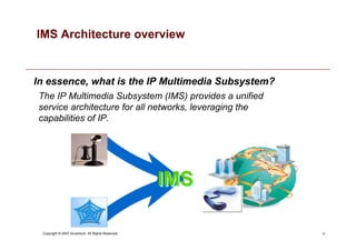
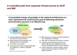
Copyright © 2007 Accenture All Rights Reserved. Accenture, its logo, and High Performance Delivered are trademarks of Accenture.
IMS architecture overview
An overview of IMS architecture and related Accenture experiences.
Università Federico II - Napoli, 27 aprile 2007
2
Copyright © 2007 Accenture All Rights Reserved.
Agenda
• Introduction
• IMS and Telecommunications Operators services
• IMS architecture
• IMS Call Flow
• Developing services within IMS
• IMS evolution: TISPAN architecture
• IMS role in Operators technology roadmaps
3
Copyright © 2007 Accenture All Rights Reserved.
Introduction
The presentation gives an overview of IMS architecture, including how it can help
telecommunication operators to achieve their goal of delivering advanced and
innovative services, with reference to Accenture International experiences within
incumbent, large and minor TelCos.
The main topics discussed are:
- IMS and Telecommunications Operators services
What is IMS and why it is important for TelCo
- IMS architecture
Elements, funtions, protocols and standards behind IMS
- IMS role in Operators technology roadmaps
How TelCo drives their business towards IMS solutions
- Accenture clients and IMS: some highlights
IMS experience and VoIP solutions in major Accenture clients
4
Copyright © 2007 Accenture All Rights Reserved.
Agenda
• Introduction
• IMS and Telecommunications Operators services
• IMS architecture
• IMS Call Flow
• Developing services within IMS
• IMS evolution: TISPAN architecture
• IMS role in Operators technology roadmaps
5
Copyright © 2007 Accenture All Rights Reserved.
The IP Multimedia Subsystem (IMS) provides a unified
service architecture for all networks, leveraging the
capabilities of IP.
IMS
IMS
In essence, what is the IP Multimedia Subsystem?
IMS Architecture overview
6
Copyright © 2007 Accenture All Rights Reserved.
BUSINESS DRIVERS
IMS offers richer user
experience with
sophisticated business
models
TECHNICAL DRIVERS
IMS is able to deliver services
faster, at lower cost
and independently of
devices, access
and media types
Control
CapEx
Increase
Revenue
Value Chain
Positioning
Service
Service
Enhancements
Enhancements
Convergence
Lower
OpEx
There are both business and technical drivers associated with IMS deployment, that
will bring benefits in service creation capabilities as well as in cost optimization
What drives IMS Deployment?
7
Copyright © 2007 Accenture All Rights Reserved.
IMS enables a packet-based network to provide multiple services
on single Control/Service Layers via different access network.
• Access agnostic
• Services independent
• Open architecture
• Multi-device
• Vendor independent
voice
data
video
— Main characteristics — — Reference architecture —
Physical Network
IMS and Service Enhancements: main keywords
Control
Transport
Physical Network
User
DB
Services
IM
VoIP Mail VoD
IP
…
IMS enabled
Integrated services platforms
From To
8
Copyright © 2007 Accenture All Rights Reserved.
A (controlled) change of paradigm in the network architectures is a
clear requirement for achieving the goal of delivering advanced
and innovative services in an efficient way
Wireless
access
Wireline access
Services
 services tightly associated with specific
terminals and access networks
 layered networks with separated, non -
integrated service control layers
 non-uniform user profiling
 IP pervasive but issues in guaranteeing QoS
and charging for real-time, integrated
services
 IMS introduces a structured, layered architecture
with “standardized” interfaces
 clear path for integrating 3G world and “internet”
 ubiquitous access to all services from any
device: IMS as access independent and all
services developed on IMS are access agnostic
 uniform support for customer profiling, service
access control and charging, integration with
“legacy” networks
IMS
A controlled path from separate infrastructures to all-IP
and IMS
Wireless
access
Wireline access
Services
9
Copyright © 2007 Accenture All Rights Reserved.
Agenda
• Introduction
• IMS and Telecommunications Operators services
• IMS architecture
• IMS Call Flow
• Developing services within IMS
• IMS evolution: TISPAN architecture
• IMS role in Operators technology roadmaps
10
Copyright © 2007 Accenture All Rights Reserved.
The IP Multimedia Subsystem is an architecture, originally defined
and standardized by the 3GPP consortium, thought to provide
multimedia services exploiting an ALL-IP domain.
IMS architecture
 IP transport offers a cheaper and simpler way to carry multimedia sessions, compared to traditional
circuit-switched networks.
 A first step toward the all-IP solution is the separation of the Control Layer from the
Transport Layer, which can therefore be implemented exploiting the IP network
 IMS steps over, redefining and standardizing the
Transport Layer, Control Layer and
Application Layer to exploit the IP
infrastructure
 The IMS solution is therefore an ALL-IP
architecture. Moreover standardization of
functions and interfaces allows:
 Interoperability with other providers
 Convergence of services
 Flexibility and extensibility of the solution
Application
Application
Layer
Layer –
– IP
IP based
based
Control
Control Layer
Layer –
–
IP
IP based
based
Transport
Transport Layer
Layer –
–
IP
IP based
based
ALL-IP Network
11
Copyright © 2007 Accenture All Rights Reserved.
IMS Overview:
Standardization Organizations
The 3rd Generation Partnership Project (3GPP) is a collaboration agreement that was established in
1998 bringing together a number of telecommunications standardization bodies. Scope of 3GPP was to
produce globally applicable Technical Specifications and Technical Reports for a 3rd Generation Mobile
Systems based on GSM, GPRS and EDGE core networks and the radio access technologies.
The European Telecommunications Standards Institute (ETSI) is an independent, non-profit organization, whose mission is to
produce telecommunications standards for today and for the future. responsible for standardization of Information and
Communication Technologies (ICT) within Europe
ETSI
TTA
ARIB ATIS
CCSA TTC
3GPP
European Telecommunications Standards
Institute is an independent, non-profit
organization, whose mission is to produce
telecommunications standards for ICT within
Europe
Asian Association of Radio
Industries and Businesses, to
conduct research  development
on utilization, realization and
popularization of new radio
systems in telecommunications
and broadcasting.
China Communication Standards
Association, to contribute to the
development of information industry
Alliance for Telecommunications Industry
Solutions (ATIS) is a U.S.-based
organization that is committed to rapidly
developing and promoting technical and
operations standards for the communications
Japanese Telecommunication
Technology Committee, with the
purpose of contributing to
standardization in the field of
telecommunications by
establishing protocols and
standards
TTA (Telecommunications Technology
Association) is an IT standards organization
that develops new standards and provides
one-stop services for the establishment of IT
standards as well as providing testing and
certification for IT products
12
Copyright © 2007 Accenture All Rights Reserved.
IMS layers and functions : overview
SS7
over IP
I-CSCF MGCF
BGCF SGW
SIP-AS
OSA-SCS
OSA-AS
IM-SSF
CSE
MGW PSTN/
PLMN
HSS
INTERNET
P-CSCF
SIP
MRFC
MRFP
Application
Layer
Control
Layer
Access and
Transport Layer
IP Core
Network
UTRAN GGSN
GGSN
OSA - API CAP
SIP
DIAMETER
MAP
DIAMETER
SIP
SIP
SIP
H.248/
Megaco
SS7 -
MTP
H.248/
Megaco
ISC
Dx
SLF
Cx
Sh
Dh
M j
M i
M n
M p
Gm
M w
M w
M r
S-CSCF
M g
ISC
ISC
Si
Fixed Network BRAS
BRAS
DSLAM
DSLAM
The resulting IMS architecture defines
elements and functions on three layers:
13
Copyright © 2007 Accenture All Rights Reserved.
IMS Core Network Element : CSCF
Call session control function
Several types of SIP servers known as CSCF are used to
process SIP signaling packets in the IMS domain:
 Proxy CSCF
 Interrogating CSCF
 Serving CSCF
The CSCF elements are responsible for SIP session control and implements the logics for the following
functions:
 user authentication
 call routing
 controlling the generation of call detail records (CDRs) for accounting purposes
Each network will typically have multiple CSCFs of each type, allowing load sharing and supporting
increased reliability through the use of backup servers.
All the CSCF will use the session initiation protocol (SIP) as signaling protocol. Interaction with other
domains using different protocols are performed by dedicated elements which allow protocol translation.
14
Copyright © 2007 Accenture All Rights Reserved.
IMS Core Network Element : P-CSCF
Proxy Call Session Control Function
A P-CSCF is the first point of contact for the IMS terminal, and performs
the following main functionalities:
 forwards the registration requests received from the UE to the I-CSCF
 forwards the SIP messages to the S-CSCF that administrate the user, whose address
is defined during the registation
 forwards the request and the answers to the UE
The P-CSCF is assigned to an IMS terminal during registration, assigned either via DHCP, or in the
PDP Context, and does not change for the duration of the registration.
 Sits on the path of all signalling messages, and can inspect every message
 Authenticates the user and establishes an IPsec security association with the IMS terminal. This prevents spoofing
attacks and replay attacks and protects the privacy of the user.
 Can compress and decompress SIP messages using SigComp, which reduces the round-trip over slow radio links
 May include a PDF (Policy Decision Function), which authorizes media plane resources e.g. quality of service (QoS)
over the media plane. It's used for policy control, bandwidth management, etc ... The PDF can also be a separate
function.
 Can be located either in the visited network (in full IMS networks) or in the home network (when the visited network is
not IMS compliant yet).
Some networks might use a Session Border Controller for this function.
15
Copyright © 2007 Accenture All Rights Reserved.
IMS Core Network Element : I-CSCF
Interrogating Call Session Control Function
An I-CSCF is a SIP function located at the edge of an
administrative domain.
 its IP address is published in the DNS of the domain (using NAPTR and
SRV type of DNS records), so that remote servers can find it, and use it
as a forwarding point (e.g. registering) for SIP packets to this domain.
 its IP address is published in the DNS of the domain (using NAPTR and SRV type of DNS records), so
that remote servers can find it, and use it as a forwarding point (e.g. registering) for SIP packets to this
domain.
 I-CSCF queries the HSS using the DIAMETER Cx interface to retrieve the user location (Dx interface
is used from I-CSCF to SLF to locate the needed HSS only), and then routes the SIP request to its
assigned S-CSCF.
 Up to Release 6 it can also be used to hide the internal network from the outside world (encrypting part
of the SIP message), in which case it's called a THIG (Topology Hiding Inter-network Gateway).
 From Release 7 onwards this entry point function is removed from the I-CSCF and is now part of the
IBCF (Interconnection Border Control Function). The IBCF is used as gateway to external networks,
and provides NAT and Firewall functions (pinholing).
16
Copyright © 2007 Accenture All Rights Reserved.
IMS Core Network Element : S-CSCF
Serving Call Session Control Function
An S-CSCF (Serving-CSCF) is the central node of the signalling
plane.
It is a SIP server always located in the home network. The S-CSCF uses
DIAMETER Cx and Dx interfaces to the HSS to download and upload user
profiles - it has no local storage of the user.
All necessary information is loaded from the HSS.
 it handles SIP registrations, which allows it to bind the user location (e.g. the IP address of the
terminal) and the SIP address
 it sits on the path of all signaling messages, and can inspect every message
 it decides to which application server(s) the SIP message will be forwarded, in order to provide their
services
 it provides routing services, typically using ENUM lookups
 it enforces the policy of the network operator
 there can be multiple S-CSCFs in the network for load distribution and high availability reasons. It's the
HSS that assigns the S-CSCF to a user, when it's queried by the I-CSCF.
17
Copyright © 2007 Accenture All Rights Reserved.
IMS Core Network Element : HSS or UPSF
Home Subscriber Server or User Profile Server Function UPSF
The HSS is the database of all subscriber and service data.
HSS is the master user database that supports the IMS network entities that
handle the call sessions:
 it contains the subscription-related information (user profiles), used by the
control layer
 It contains subcription information used by the service layer
 it provides data used to perform authentication and authorization of the user
 it can provide information about the physical location of user
The HSS also provides the traditional Home Location Register (HLR) and Authentication Centre (AUC)
functions. This allows the user to access the packet and circuit domains of the network initially, via IMSI
authentication.
User Profile is composed by:
 user identity
 allocated S-CSCF name
 Registration information and roaming profile
 authentication parameters
 Control and service information.
18
Copyright © 2007 Accenture All Rights Reserved.
IMS Core Network Element : SLF
Subscription Locator Function
An SLF is needed to map user addresses when multiple HSSs
are used.
The Subscription Locator Function (SLF) is used in a IMS network as a
resolution mechanism that enables the I-CSCF, the S-CSCF and the AS to
find the address of the HSS that holds the subscriber data for a given user
identity when multiple and separately addressable HSSs have been deployed
by the network operator.
The SLF expose Dx and Dh interfaces, which have the same syntax and semantic of the Cx and Sh
interfaces provided by the HSS.
The SLF does not perform any logic on its interfaces, but replies to the requestor with a REDIRECT
message, specifying the address of the HSS which is able to fulfill the request received.
Both the HSS and the SLF communicate through the DIAMETER protocol.
19
Copyright © 2007 Accenture All Rights Reserved.
IMS Core Network Element : MRF
Media Resource Function
An MRF is a source for network initiated and network
managed media streams in the home network.
It is exploited for :
– Playing of announcements (audio/video)
– Multimedia conferencing (e.g. mixing of audio streams)
– Text-to-speech conversion (TTS) and speech recognition.
– Realtime transcoding of multimedia data (i.e. conversion between different codecs)
Each MRF is further divided into :
– An MRFC (Media Resource Function Controller) is a signalling plane node that acts as a SIP
User Agent to the S-CSCF, and which controls the MRFP with a H.248 interface
– An MRFP (Media Resource Function Processor) is a media plane node that implements all
media-related functions.
20
Copyright © 2007 Accenture All Rights Reserved.
IMS Core Network Element : BGCF
Break Out Gateway Control Function
The Breakout Gateway Control Function is the IMS element
that selects the network in which PSTN breakout has to
occur.
A BGCF is used for calls from the IMS to a phone in a Circuit
Switched network, such as the PSTN or the PLMN.
BGCF forwards the signaling to the selected PSTN/PLMN network.
If the breakout occurs in the same network as the BGCF then the BGCF selects a MGCF
(Media Gateway Control Function) that will be responsible for inter-working with the PSTN,
and forwards the signaling to MGCF. Otherwise it forwards signaling to BCGF of another
operator network
The MGCF then receives the SIP signalling from the BGCF and manages the interworking
with the PSTN network.
21
Copyright © 2007 Accenture All Rights Reserved.
IMS Core Network Element : PSTN Gateways
Public Switched Telephony Network Gateways
The interworking with the Circuit Switched network is realized by
several components, for signaling, media and control
functionalities:
SGW (Signalling Gateway)
is the interface with the signaling plane of the Circuit Switched Network (CS).
It transforms lower layer protocols as SCTP (which is an IP protocol) into MTP
(which is a SS7 protocol), to pass ISUP from the MGCF to the CS network.
MGCF (Media Gateway Controller Function)
– Performs call control protocol conversion between SIP and ISUP
– interfaces the SGW over SCTP
– controls the MGW resources with a H.248 interface.
•MGW (Media Gateway)
– Interfaces the media plane of the CS network, by converting between RTP
and PCM.
– It can also perfom media transcoding, when the codecs used do not match
(e.g. IMS might use AMR, PSTN might use G.711).
22
Copyright © 2007 Accenture All Rights Reserved.
IMS Core Network Element : AS
Application Servers
Application Servers host and execute services, and interface with
the S-CSCF using SIP.
This allows third party providers an easy integration and deployment of their
value added services to the IMS infrastructure.
Examples of services are:
– Caller ID related services (CLIP, CLIR, ...)
– Call waiting, Call hold, Call pick up
– Call forwarding, Call transfer
– Call blocking services, Malicious Caller Identification
– Lawful interception
– Announcements, Digit collection
– Conference call services
– Location based services
– SMS, MMS
– Presence information, Instant messaging
– Voice Call Continuity Function (VCC Server) or Fixed Mobile Convergence
23
Copyright © 2007 Accenture All Rights Reserved.
IMS Core Network Element : IM-SSF
IP Multimedia - Service Switching Function
The IM-SSF is the node in the IMS domain which provides inter-
working between the SIP session control and the Intelligent
Network of traditional networks.
It allowing service requests to be forwarded to legacy service delivery platforms
such as IN-based SCPs.
IM-SSF provides intelligent gateway functionality between the SIP-based IMS
network and IN systems that use protocols such as CAMEL, INAP, AIN and MAP
This functionality is critical for the rollout of new, converged offerings, while
continuing service to high-value customers.
The IM-SSF also enables access to subscriber information retrieved from the
HSS over the Si interface using the MAP protocol.
24
Copyright © 2007 Accenture All Rights Reserved.
IMS Core Network Element : Service Layer
Interfaces
– ISC (between S-CSCF and OSA Gateway/IM-SSF/SIP AS) allows to receive/notify SIP messages from/to
the S-CSCF to realize the service session control
– Cx beetwen S-CSCF and HSS is used to retrieve/update the subscriber profile data
– Sh between HSS/OSA- Gateway/SIP-AS is used to retrieve/update the subscriber profile data related to
the service. The HSS is responsible for policing what information will be provided to each individual
application server.
– Si between HSS and IM-SSF is used to retrieve/update the subscriber profile data related to IN services
The IMS control layer implements several interfaces toward the service layer which enables the user
to access to service logics implemented by heterogeneous resources and application servers.
IMS Operator
(OSA API)
3rd Party Service
Provider
S-CSCF (IMS Call Control Function)
IM-SSF
HSS
CSE/
IN legacy
SIP AS
OSA
Gateway
SIP
(ISC Interface)
SIP
Services
IN legacy
Services
OSA AS OSA AS
CAP
SIP
(ISC interfcae)
SIP
(ISC interface)
Diameter
(Cx interface)
Diameter
(Sh interface)
(Si Interface)
(OSA API)
OSA
Compliant
Services
Third Party
Services
25
Copyright © 2007 Accenture All Rights Reserved.
Agenda
• Introduction
• IMS and Telecommunications Operators services
• IMS architecture
• IMS Call Flow
• Developing services within IMS
• IMS evolution: TISPAN architecture
• IMS role in Operators technology roadmaps
26
Copyright © 2007 Accenture All Rights Reserved.
IMS
domain A
UE 1
Registration
IMS domain B
UE 3
Before starting a multimedia session, the
UE must register to the IMS domain.
Example: Registration and Basic Call Flow
UE 2
P–CSCF
S–CSCF
S–CSCF
I–CSCF
P–CSCF
HSS
S–CSCF
UE 1 UE 2
HSS
I–CSCF
27
Copyright © 2007 Accenture All Rights Reserved.
IMS
domain A
UE 1
Session set up
UE in different IMS domain
IMS domain B
UE 3
The session origination procedures specify the
signaling path between the UE initiating a
session setup attempt and the Serving-CSCF
that is assigned to perform the session
origination service. This signaling path is
determined at the time of UE registration, and
remains fixed for the life of the registration.
Example: Registration and Basic Call Flow
UE 2
P–CSCF
S–CSCF
S–CSCF
I–CSCF
P–CSCF
HSS
S–CSCF
UE 1 UE 2
HSS
I–CSCF
28
Copyright © 2007 Accenture All Rights Reserved.
IMS
domain A
UE 1
Session set up
UE in the same IMS domain
IMS domain B
UE 3
The session origination procedures specify the
signaling path between the UE initiating a
session setup attempt and the Serving-CSCF
that is assigned to perform the session
origination service. This signaling path is
determined at the time of UE registration, and
remains fixed for the life of the registration.
Example: Registration and Basic Call Flow
UE 2
P–CSCF
S–CSCF
S–CSCF
I–CSCF
P–CSCF
HSS
S–CSCF
UE 1 UE 2
HSS
I–CSCF
29
Copyright © 2007 Accenture All Rights Reserved.
IN SCP
IN SCP
Number
Portability
IM-SSF
P-I-S-CSCF HSS
ISC
Si
Cx
INAP
User A initiates a call to a number that has been ported to an external network.
User A has the Call Barring service, which prevents him to call 1xx numbers, hence the S-CSCF triggers the
Application Server to apply the CB logic. The AS retrieves the profile associated to User A from the HSS,
perform the service logic, and sends back the message to the S-CSCF allowing the call.
U.A. A
U.A. B
AS
Call
Barring
Sh
ISC
Call control comes back to the CSCF,
which interrogates the HSS and
recognizes the dialed number has been
‘ported’ to an external network. The S-
CSCF forward the request to the IM-SSF
to apply the Number Portability service
on the Intelligent Network.
The IM-SSF forwards the request to the
SCP using INAP, which responds with
the new Routing Number of the User B.
The IM-SSF responds to the S-CSCF
with the new number.
The CSCF completes the signaling
phase forwarding the call to the BGCP,
and finally to the called party User B.
Example: Call Flow with services :
Call Barring and Number Portability
BGCF
30
Copyright © 2007 Accenture All Rights Reserved.
Agenda
• Introduction
• IMS and Telecommunications Operators services
• IMS architecture
• IMS Call Flow
• Developing services within IMS
• IMS evolution: TISPAN architecture
• IMS role in Operators technology roadmaps
31
Copyright © 2007 Accenture All Rights Reserved.
Developing and deploying applications
• Applications deployed on ASs are the basic blocks used to develop services.
• Services can be provided directly by a single application or can be the result of the orchestration of
several applications, eventually hosted on different Application Servers.
• Application Servers are the execution environments for applications, providing framework facilities
such as protocols and interface support, database connections, security, monitoring and more…
Southbound systems
Application Server
NB
i/f
Presentation Interfaces
Service
Logics
Layer
SB
i/f
Protocols
Data
Layer
Data
Listeners
Connectors
Execution Environment
Libraries APIs
Applications
Applications
Applications
DB i/f
DB
Connections
Conn
Pools
OSS i/f
Fault
Mgmt
Configuration
Performnance
Assurance
Security
OSS
BSS
BSS i/f
Charging
32
Copyright © 2007 Accenture All Rights Reserved.
SLEE and Servlet-Container architectures
Fine grained (‘Grana Fine’)
• Allows more granularity in management of
the requests
Coarse grained (‘Grana grossa’)
• Does not allow to manage same request in
different way
Service model: Publish/subscribe
• Requests have not a direct connection with
service blocks
Service model: Request/response
• Direct association between messages and
logics
Asynchronous execution
• Requests generate events. Service logics
are notified of raised events, and activate
services
Synchronous execution:
• Logics are activated by requests received
from the network
Event Driven, SLEE
Message Driven, Servlet Containers
• Application Containers can be based on different paradigms, depending on the structure of the
application execution environment and on the technique used to convey messages between different
components inside the application server.
Two main execution environments types are currently exploited to develop application servers:
33
Copyright © 2007 Accenture All Rights Reserved.
Application Architectures: SLEE
External system
SLEE Container
Resource
Adapter
SBB
Resource
Adapter
Resource
Adapter
SBB SBB SBB
Events Collector
Event Dispatcher
SLEE (Service Logic Execution Environment) architecture is based on an execution model with
application hosted as independent service building blocks (SBB).
 Each SBB can be triggered and activated by one or more events, generated inside the SLEE
 Interfaces are realized implementing Resource Adaptors, which manage listeners and protocols, and
are able to raise specific events when interrogated by network requests.
 The SLEE environments manages the entire lifecycle of events, applying subscribe/notify and routing
rules between RAs and SBBs.
This kind of service environment has been
specifically thought for TelCo operators, as
allows following features:
 Modular development of service logics
 Easy combination of different Service
Block to provide convergent services
 Resource Adapters can be added or
extended without modifying the service
logics implemented inside SBBs
34
Copyright © 2007 Accenture All Rights Reserved.
Application Architectures: Servlet Containers
External system
Servlet Container
Protocol
Listener
Service
Protocol
Listener
Protocol
Listener
Service Service Service
Servlet Containers are execution environments which bind the execution of a service logic to the
receiving of a particular request.
 Service Logic lifecycle is entirely managed by the environment
 Requests are associated to service logics depending on the type of message received (servlet model)
 Service Logics are activated synchronously with request elaboration
 Combination of service logics is managed redirecting messages inside the container
The servlet paradigm can be used
implementing adaptors for several protocols,
allowing the development of fast network
oriented services:
 Service Logics are directly connected to
network messages
 Can manage queuing, overloading and
prioritization of requests
 Protocols and interfaces can be added
implementing new listeners
Execution
queue
Execution
queue
Execution
queue
Execution
queue
35
Copyright © 2007 Accenture All Rights Reserved.
Agenda
• Introduction
• IMS and Telecommunications Operators services
• IMS architecture
• IMS Call Flow
• Developing services within IMS
• IMS evolution: TISPAN architecture
• IMS role in Operators technology roadmaps
36
Copyright © 2007 Accenture All Rights Reserved.
IMS evolution: NGN Tispan Architecture
•This focus on fixed accesses together with the choice of using the IMS network in the core architecture led to
new requirements and to an evolution of the original IMS solution.
TISPAN and 3GPP are now working together to define a harmonized IMS-centric core for both wireless and
wireline networks, enabling new convergent accesses and services.
The Telecoms  Internet converged Services  Protocols for Advanced Networks (TISPAN) is a
standardization body of ETSI, specializing in fixed networks and Internet convergence.
TISPAN is the ETSI core competence centre for fixed networks and for migration from switched circuit
networks to packet-based networks with an architecture that can serve in both to create the Next Generation
Network.
Wireless access Wireline access
3GPP /
IMS
TISPAN
AGW
AGW
37
Copyright © 2007 Accenture All Rights Reserved.
IMS evolution: NGN Tispan Architecture
•This subsystem-oriented architecture enables the addition of new subsystems over the time to cover new
demands and service classes. The architecture ensures that the network resources, applications, and user
equipment are common to all subsystems and therefore ensure user, terminal and service mobility to the
fullest extent possible, including across administrative boundaries.
The NGN standard functional architecture, defined by TISPAN, is composed by a “service layer”
and a “transport-layer” both based on IP.
38
Copyright © 2007 Accenture All Rights Reserved.
TISPAN NGN solution is based on a subsystem–oriented architecture, enabling the insertion of
new subsystems over the time to cover new demands and providing the ability to import/adapt
subsystems defined within other standardization bodies.
TISPAN – NGN Functional Architecture (2/2)
Service Layer Components
Transport Layer
Components
The service layer comprises:
 Core IP Multimedia Subsystem (IMS)
 PSTN/ISDN Emulation Subsystem
(PES)
 Other subsystems (e.g. streaming
subsystem, content broadcasting
subsystem etc.) and applications
 Common components used by several
subsystems, such as:
-charging functions
-user profile management
-security management
-routing data bases (e.g. ENUM)
IP Connectivity is provided to the user
equipment by the Transport Layer.
The transport layer comprises a transport
control sub layer on top of transfer
functions.
The transport control sub layer
is further divided in two subsystems:
 Network Attachment Subsystem
(NASS)
 the Resource and Admission
Control Subsystem (RACS).
39
Copyright © 2007 Accenture All Rights Reserved.
NASS – Network Attachment SubSystem
NASS is a Transport Control layer element defined by ETSI /
TISPAN
NASS system provides integrated and centralized
management of users access to the network
NASS makes possible to expose towards upper-layer systems users presence informations and at the
same time apply policies to control network access based on varoius users profiles
 NASS functionalities cover:
 Authentication and authorization
 Dynamic or static IP address assignment
 Access devices configuration
 Assignment of the proxy to access to IMS services (i.e. P-CSCF)
 Access parameters management (i.e. QoS, bandwidth )
 Management of network presence towards application layers
 Mobility features
40
Copyright © 2007 Accenture All Rights Reserved.
RACS (Resource and Admission Control
Subsystem)
Racs main functionalities are:
 Admission Control, which enforce limitations to the access to
network resources, e.g. applying bandwidth thresholds
 Resource reservation, which enable the reservation, for a given
period, of the resources needed to provide a service. For example a
voice call will reserve a given bandwidth over the entire circuit
before the call is initiated
 Policy Control, enable enforcement of policies on the resource
exploitation
RACS is the TISPAN element in the transport control layer
responsible of policy control, resource reservation and
admission control.
41
Copyright © 2007 Accenture All Rights Reserved.
Agenda
• Introduction
• IMS and Telecommunications Operators services
• IMS architecture
• IMS Call Flow
• Developing services within IMS
• IMS evolution: TISPAN architecture
• IMS role in Operators technology roadmaps
42
Copyright © 2007 Accenture All Rights Reserved.
Program and Project Management
Service-driven Vs. network-driven NGN approach
Strategy
Marketing 
Service
Requiremen
ts
Services
and
Network
Architecture
Design
Development  Test
Service
Development
Products Devp

Customization
Platforms
and Network
Deployment
E2E
Integration
Tests
Roll Out Operation
s
Evolution
Market Trial
deployment
Market Trial Operation
Service-driven approach Network-driven approach
• Multiple complex
network
configuration
required for an
heterogeneous
environment
• Launch  Tune
single “buildings
blocks” enabling
services due to
the faced
approach
Operational
Excellence
• Develop interfaces
between existing
and new networks
elements (low
reusability)
• Incremental
Capex due to
progressive
services Launch
Cost
Effectiveness
Cons
Pros
• Technologies and
standards are
evolving, products
obsolescence
management
needed
• Efficient Service
Creation and
Delivery
Operational
Excellence
• Costly and
challenging
deployment due to
an “in one swoop”
overhauled network
• Opex decrease
due to an
integrated and
homogeneous
environment
Cost
Effectiveness
Cons
Pros
43
Copyright © 2007 Accenture All Rights Reserved.
IMS is going to play a key role in Operators technology context for controlling and enabling the
introduction of innovative/convergent services in an ALL IP environment
IMS role in Operators technology roadmaps
 IMS is emerging as the de facto convergence model for fixed, mobile and enterprise telephony. IMS
will be used to keep control of the network while using IP technologies: Service and Control Layers
will be implemented using IMS architectures as a key: element to support both IP multimedia
sessions over heterogeneous media type.
 IMS architecture will be used as “the” mean for obtaining fixed and mobile convergence (3GPP-
TISPAN): different IMSs for mobile and fixed networks will be integrated and merged into a
single infrastructure (e.g. single HSS –Data Base for all users)
 Innovative and advanced Services (e.g. combinational ones) will leverage convergent IMS-enabled
Service Layer
 IMS alone is not enough, it will be complemented with additional functional elements such as:
external interfaces, databases, enablers (presence, location,…), QoS server, media server, IMS-
enabled terminals
44
Copyright © 2007 Accenture All Rights Reserved.
Service interconnection
PSTN PLMN
IP
Transport
Control
IMS
PSTN
Services
IN Services Circuit
Switched
Services
IP Services Packet
Switched
Services
Service interconnections with legacy and consolidated platforms in the short term
and with non-IMS platforms will be needed to deliver the integrated experience that
users ask for.
IMS in the existing Provider’s service environment is not
alone…
45
Copyright © 2007 Accenture All Rights Reserved.
…and Service Delivery Platform provides
the needed functions to support IMS
integration and service creation
PSTN PLMN
IP
Transport
Control
IMS
PSTN
Services
IN Services CS
Services
IP Services PS
Services
Service Control
Service Creation and Execution
Core Services
Service Orchestration
3P-
GW
Service
Service Delivery
Delivery Platform
Platform

AT_2006-07_IMS_Accenture.pdf

  • 1.
    Copyright © 2007Accenture All Rights Reserved. Accenture, its logo, and High Performance Delivered are trademarks of Accenture. IMS architecture overview An overview of IMS architecture and related Accenture experiences. Università Federico II - Napoli, 27 aprile 2007
  • 2.
    2 Copyright © 2007Accenture All Rights Reserved. Agenda • Introduction • IMS and Telecommunications Operators services • IMS architecture • IMS Call Flow • Developing services within IMS • IMS evolution: TISPAN architecture • IMS role in Operators technology roadmaps
  • 3.
    3 Copyright © 2007Accenture All Rights Reserved. Introduction The presentation gives an overview of IMS architecture, including how it can help telecommunication operators to achieve their goal of delivering advanced and innovative services, with reference to Accenture International experiences within incumbent, large and minor TelCos. The main topics discussed are: - IMS and Telecommunications Operators services What is IMS and why it is important for TelCo - IMS architecture Elements, funtions, protocols and standards behind IMS - IMS role in Operators technology roadmaps How TelCo drives their business towards IMS solutions - Accenture clients and IMS: some highlights IMS experience and VoIP solutions in major Accenture clients
  • 4.
    4 Copyright © 2007Accenture All Rights Reserved. Agenda • Introduction • IMS and Telecommunications Operators services • IMS architecture • IMS Call Flow • Developing services within IMS • IMS evolution: TISPAN architecture • IMS role in Operators technology roadmaps
  • 5.
    5 Copyright © 2007Accenture All Rights Reserved. The IP Multimedia Subsystem (IMS) provides a unified service architecture for all networks, leveraging the capabilities of IP. IMS IMS In essence, what is the IP Multimedia Subsystem? IMS Architecture overview
  • 6.
    6 Copyright © 2007Accenture All Rights Reserved. BUSINESS DRIVERS IMS offers richer user experience with sophisticated business models TECHNICAL DRIVERS IMS is able to deliver services faster, at lower cost and independently of devices, access and media types Control CapEx Increase Revenue Value Chain Positioning Service Service Enhancements Enhancements Convergence Lower OpEx There are both business and technical drivers associated with IMS deployment, that will bring benefits in service creation capabilities as well as in cost optimization What drives IMS Deployment?
  • 7.
    7 Copyright © 2007Accenture All Rights Reserved. IMS enables a packet-based network to provide multiple services on single Control/Service Layers via different access network. • Access agnostic • Services independent • Open architecture • Multi-device • Vendor independent voice data video — Main characteristics — — Reference architecture — Physical Network IMS and Service Enhancements: main keywords Control Transport Physical Network User DB Services IM VoIP Mail VoD IP … IMS enabled Integrated services platforms From To
  • 8.
    8 Copyright © 2007Accenture All Rights Reserved. A (controlled) change of paradigm in the network architectures is a clear requirement for achieving the goal of delivering advanced and innovative services in an efficient way Wireless access Wireline access Services services tightly associated with specific terminals and access networks layered networks with separated, non - integrated service control layers non-uniform user profiling IP pervasive but issues in guaranteeing QoS and charging for real-time, integrated services IMS introduces a structured, layered architecture with “standardized” interfaces clear path for integrating 3G world and “internet” ubiquitous access to all services from any device: IMS as access independent and all services developed on IMS are access agnostic uniform support for customer profiling, service access control and charging, integration with “legacy” networks IMS A controlled path from separate infrastructures to all-IP and IMS Wireless access Wireline access Services
  • 9.
    9 Copyright © 2007Accenture All Rights Reserved. Agenda • Introduction • IMS and Telecommunications Operators services • IMS architecture • IMS Call Flow • Developing services within IMS • IMS evolution: TISPAN architecture • IMS role in Operators technology roadmaps
  • 10.
    10 Copyright © 2007Accenture All Rights Reserved. The IP Multimedia Subsystem is an architecture, originally defined and standardized by the 3GPP consortium, thought to provide multimedia services exploiting an ALL-IP domain. IMS architecture IP transport offers a cheaper and simpler way to carry multimedia sessions, compared to traditional circuit-switched networks. A first step toward the all-IP solution is the separation of the Control Layer from the Transport Layer, which can therefore be implemented exploiting the IP network IMS steps over, redefining and standardizing the Transport Layer, Control Layer and Application Layer to exploit the IP infrastructure The IMS solution is therefore an ALL-IP architecture. Moreover standardization of functions and interfaces allows: Interoperability with other providers Convergence of services Flexibility and extensibility of the solution Application Application Layer Layer – – IP IP based based Control Control Layer Layer – – IP IP based based Transport Transport Layer Layer – – IP IP based based ALL-IP Network
  • 11.
    11 Copyright © 2007Accenture All Rights Reserved. IMS Overview: Standardization Organizations The 3rd Generation Partnership Project (3GPP) is a collaboration agreement that was established in 1998 bringing together a number of telecommunications standardization bodies. Scope of 3GPP was to produce globally applicable Technical Specifications and Technical Reports for a 3rd Generation Mobile Systems based on GSM, GPRS and EDGE core networks and the radio access technologies. The European Telecommunications Standards Institute (ETSI) is an independent, non-profit organization, whose mission is to produce telecommunications standards for today and for the future. responsible for standardization of Information and Communication Technologies (ICT) within Europe ETSI TTA ARIB ATIS CCSA TTC 3GPP European Telecommunications Standards Institute is an independent, non-profit organization, whose mission is to produce telecommunications standards for ICT within Europe Asian Association of Radio Industries and Businesses, to conduct research development on utilization, realization and popularization of new radio systems in telecommunications and broadcasting. China Communication Standards Association, to contribute to the development of information industry Alliance for Telecommunications Industry Solutions (ATIS) is a U.S.-based organization that is committed to rapidly developing and promoting technical and operations standards for the communications Japanese Telecommunication Technology Committee, with the purpose of contributing to standardization in the field of telecommunications by establishing protocols and standards TTA (Telecommunications Technology Association) is an IT standards organization that develops new standards and provides one-stop services for the establishment of IT standards as well as providing testing and certification for IT products
  • 12.
    12 Copyright © 2007Accenture All Rights Reserved. IMS layers and functions : overview SS7 over IP I-CSCF MGCF BGCF SGW SIP-AS OSA-SCS OSA-AS IM-SSF CSE MGW PSTN/ PLMN HSS INTERNET P-CSCF SIP MRFC MRFP Application Layer Control Layer Access and Transport Layer IP Core Network UTRAN GGSN GGSN OSA - API CAP SIP DIAMETER MAP DIAMETER SIP SIP SIP H.248/ Megaco SS7 - MTP H.248/ Megaco ISC Dx SLF Cx Sh Dh M j M i M n M p Gm M w M w M r S-CSCF M g ISC ISC Si Fixed Network BRAS BRAS DSLAM DSLAM The resulting IMS architecture defines elements and functions on three layers:
  • 13.
    13 Copyright © 2007Accenture All Rights Reserved. IMS Core Network Element : CSCF Call session control function Several types of SIP servers known as CSCF are used to process SIP signaling packets in the IMS domain: Proxy CSCF Interrogating CSCF Serving CSCF The CSCF elements are responsible for SIP session control and implements the logics for the following functions: user authentication call routing controlling the generation of call detail records (CDRs) for accounting purposes Each network will typically have multiple CSCFs of each type, allowing load sharing and supporting increased reliability through the use of backup servers. All the CSCF will use the session initiation protocol (SIP) as signaling protocol. Interaction with other domains using different protocols are performed by dedicated elements which allow protocol translation.
  • 14.
    14 Copyright © 2007Accenture All Rights Reserved. IMS Core Network Element : P-CSCF Proxy Call Session Control Function A P-CSCF is the first point of contact for the IMS terminal, and performs the following main functionalities: forwards the registration requests received from the UE to the I-CSCF forwards the SIP messages to the S-CSCF that administrate the user, whose address is defined during the registation forwards the request and the answers to the UE The P-CSCF is assigned to an IMS terminal during registration, assigned either via DHCP, or in the PDP Context, and does not change for the duration of the registration. Sits on the path of all signalling messages, and can inspect every message Authenticates the user and establishes an IPsec security association with the IMS terminal. This prevents spoofing attacks and replay attacks and protects the privacy of the user. Can compress and decompress SIP messages using SigComp, which reduces the round-trip over slow radio links May include a PDF (Policy Decision Function), which authorizes media plane resources e.g. quality of service (QoS) over the media plane. It's used for policy control, bandwidth management, etc ... The PDF can also be a separate function. Can be located either in the visited network (in full IMS networks) or in the home network (when the visited network is not IMS compliant yet). Some networks might use a Session Border Controller for this function.
  • 15.
    15 Copyright © 2007Accenture All Rights Reserved. IMS Core Network Element : I-CSCF Interrogating Call Session Control Function An I-CSCF is a SIP function located at the edge of an administrative domain. its IP address is published in the DNS of the domain (using NAPTR and SRV type of DNS records), so that remote servers can find it, and use it as a forwarding point (e.g. registering) for SIP packets to this domain. its IP address is published in the DNS of the domain (using NAPTR and SRV type of DNS records), so that remote servers can find it, and use it as a forwarding point (e.g. registering) for SIP packets to this domain. I-CSCF queries the HSS using the DIAMETER Cx interface to retrieve the user location (Dx interface is used from I-CSCF to SLF to locate the needed HSS only), and then routes the SIP request to its assigned S-CSCF. Up to Release 6 it can also be used to hide the internal network from the outside world (encrypting part of the SIP message), in which case it's called a THIG (Topology Hiding Inter-network Gateway). From Release 7 onwards this entry point function is removed from the I-CSCF and is now part of the IBCF (Interconnection Border Control Function). The IBCF is used as gateway to external networks, and provides NAT and Firewall functions (pinholing).
  • 16.
    16 Copyright © 2007Accenture All Rights Reserved. IMS Core Network Element : S-CSCF Serving Call Session Control Function An S-CSCF (Serving-CSCF) is the central node of the signalling plane. It is a SIP server always located in the home network. The S-CSCF uses DIAMETER Cx and Dx interfaces to the HSS to download and upload user profiles - it has no local storage of the user. All necessary information is loaded from the HSS. it handles SIP registrations, which allows it to bind the user location (e.g. the IP address of the terminal) and the SIP address it sits on the path of all signaling messages, and can inspect every message it decides to which application server(s) the SIP message will be forwarded, in order to provide their services it provides routing services, typically using ENUM lookups it enforces the policy of the network operator there can be multiple S-CSCFs in the network for load distribution and high availability reasons. It's the HSS that assigns the S-CSCF to a user, when it's queried by the I-CSCF.
  • 17.
    17 Copyright © 2007Accenture All Rights Reserved. IMS Core Network Element : HSS or UPSF Home Subscriber Server or User Profile Server Function UPSF The HSS is the database of all subscriber and service data. HSS is the master user database that supports the IMS network entities that handle the call sessions: it contains the subscription-related information (user profiles), used by the control layer It contains subcription information used by the service layer it provides data used to perform authentication and authorization of the user it can provide information about the physical location of user The HSS also provides the traditional Home Location Register (HLR) and Authentication Centre (AUC) functions. This allows the user to access the packet and circuit domains of the network initially, via IMSI authentication. User Profile is composed by: user identity allocated S-CSCF name Registration information and roaming profile authentication parameters Control and service information.
  • 18.
    18 Copyright © 2007Accenture All Rights Reserved. IMS Core Network Element : SLF Subscription Locator Function An SLF is needed to map user addresses when multiple HSSs are used. The Subscription Locator Function (SLF) is used in a IMS network as a resolution mechanism that enables the I-CSCF, the S-CSCF and the AS to find the address of the HSS that holds the subscriber data for a given user identity when multiple and separately addressable HSSs have been deployed by the network operator. The SLF expose Dx and Dh interfaces, which have the same syntax and semantic of the Cx and Sh interfaces provided by the HSS. The SLF does not perform any logic on its interfaces, but replies to the requestor with a REDIRECT message, specifying the address of the HSS which is able to fulfill the request received. Both the HSS and the SLF communicate through the DIAMETER protocol.
  • 19.
    19 Copyright © 2007Accenture All Rights Reserved. IMS Core Network Element : MRF Media Resource Function An MRF is a source for network initiated and network managed media streams in the home network. It is exploited for : – Playing of announcements (audio/video) – Multimedia conferencing (e.g. mixing of audio streams) – Text-to-speech conversion (TTS) and speech recognition. – Realtime transcoding of multimedia data (i.e. conversion between different codecs) Each MRF is further divided into : – An MRFC (Media Resource Function Controller) is a signalling plane node that acts as a SIP User Agent to the S-CSCF, and which controls the MRFP with a H.248 interface – An MRFP (Media Resource Function Processor) is a media plane node that implements all media-related functions.
  • 20.
    20 Copyright © 2007Accenture All Rights Reserved. IMS Core Network Element : BGCF Break Out Gateway Control Function The Breakout Gateway Control Function is the IMS element that selects the network in which PSTN breakout has to occur. A BGCF is used for calls from the IMS to a phone in a Circuit Switched network, such as the PSTN or the PLMN. BGCF forwards the signaling to the selected PSTN/PLMN network. If the breakout occurs in the same network as the BGCF then the BGCF selects a MGCF (Media Gateway Control Function) that will be responsible for inter-working with the PSTN, and forwards the signaling to MGCF. Otherwise it forwards signaling to BCGF of another operator network The MGCF then receives the SIP signalling from the BGCF and manages the interworking with the PSTN network.
  • 21.
    21 Copyright © 2007Accenture All Rights Reserved. IMS Core Network Element : PSTN Gateways Public Switched Telephony Network Gateways The interworking with the Circuit Switched network is realized by several components, for signaling, media and control functionalities: SGW (Signalling Gateway) is the interface with the signaling plane of the Circuit Switched Network (CS). It transforms lower layer protocols as SCTP (which is an IP protocol) into MTP (which is a SS7 protocol), to pass ISUP from the MGCF to the CS network. MGCF (Media Gateway Controller Function) – Performs call control protocol conversion between SIP and ISUP – interfaces the SGW over SCTP – controls the MGW resources with a H.248 interface. •MGW (Media Gateway) – Interfaces the media plane of the CS network, by converting between RTP and PCM. – It can also perfom media transcoding, when the codecs used do not match (e.g. IMS might use AMR, PSTN might use G.711).
  • 22.
    22 Copyright © 2007Accenture All Rights Reserved. IMS Core Network Element : AS Application Servers Application Servers host and execute services, and interface with the S-CSCF using SIP. This allows third party providers an easy integration and deployment of their value added services to the IMS infrastructure. Examples of services are: – Caller ID related services (CLIP, CLIR, ...) – Call waiting, Call hold, Call pick up – Call forwarding, Call transfer – Call blocking services, Malicious Caller Identification – Lawful interception – Announcements, Digit collection – Conference call services – Location based services – SMS, MMS – Presence information, Instant messaging – Voice Call Continuity Function (VCC Server) or Fixed Mobile Convergence
  • 23.
    23 Copyright © 2007Accenture All Rights Reserved. IMS Core Network Element : IM-SSF IP Multimedia - Service Switching Function The IM-SSF is the node in the IMS domain which provides inter- working between the SIP session control and the Intelligent Network of traditional networks. It allowing service requests to be forwarded to legacy service delivery platforms such as IN-based SCPs. IM-SSF provides intelligent gateway functionality between the SIP-based IMS network and IN systems that use protocols such as CAMEL, INAP, AIN and MAP This functionality is critical for the rollout of new, converged offerings, while continuing service to high-value customers. The IM-SSF also enables access to subscriber information retrieved from the HSS over the Si interface using the MAP protocol.
  • 24.
    24 Copyright © 2007Accenture All Rights Reserved. IMS Core Network Element : Service Layer Interfaces – ISC (between S-CSCF and OSA Gateway/IM-SSF/SIP AS) allows to receive/notify SIP messages from/to the S-CSCF to realize the service session control – Cx beetwen S-CSCF and HSS is used to retrieve/update the subscriber profile data – Sh between HSS/OSA- Gateway/SIP-AS is used to retrieve/update the subscriber profile data related to the service. The HSS is responsible for policing what information will be provided to each individual application server. – Si between HSS and IM-SSF is used to retrieve/update the subscriber profile data related to IN services The IMS control layer implements several interfaces toward the service layer which enables the user to access to service logics implemented by heterogeneous resources and application servers. IMS Operator (OSA API) 3rd Party Service Provider S-CSCF (IMS Call Control Function) IM-SSF HSS CSE/ IN legacy SIP AS OSA Gateway SIP (ISC Interface) SIP Services IN legacy Services OSA AS OSA AS CAP SIP (ISC interfcae) SIP (ISC interface) Diameter (Cx interface) Diameter (Sh interface) (Si Interface) (OSA API) OSA Compliant Services Third Party Services
  • 25.
    25 Copyright © 2007Accenture All Rights Reserved. Agenda • Introduction • IMS and Telecommunications Operators services • IMS architecture • IMS Call Flow • Developing services within IMS • IMS evolution: TISPAN architecture • IMS role in Operators technology roadmaps
  • 26.
    26 Copyright © 2007Accenture All Rights Reserved. IMS domain A UE 1 Registration IMS domain B UE 3 Before starting a multimedia session, the UE must register to the IMS domain. Example: Registration and Basic Call Flow UE 2 P–CSCF S–CSCF S–CSCF I–CSCF P–CSCF HSS S–CSCF UE 1 UE 2 HSS I–CSCF
  • 27.
    27 Copyright © 2007Accenture All Rights Reserved. IMS domain A UE 1 Session set up UE in different IMS domain IMS domain B UE 3 The session origination procedures specify the signaling path between the UE initiating a session setup attempt and the Serving-CSCF that is assigned to perform the session origination service. This signaling path is determined at the time of UE registration, and remains fixed for the life of the registration. Example: Registration and Basic Call Flow UE 2 P–CSCF S–CSCF S–CSCF I–CSCF P–CSCF HSS S–CSCF UE 1 UE 2 HSS I–CSCF
  • 28.
    28 Copyright © 2007Accenture All Rights Reserved. IMS domain A UE 1 Session set up UE in the same IMS domain IMS domain B UE 3 The session origination procedures specify the signaling path between the UE initiating a session setup attempt and the Serving-CSCF that is assigned to perform the session origination service. This signaling path is determined at the time of UE registration, and remains fixed for the life of the registration. Example: Registration and Basic Call Flow UE 2 P–CSCF S–CSCF S–CSCF I–CSCF P–CSCF HSS S–CSCF UE 1 UE 2 HSS I–CSCF
  • 29.
    29 Copyright © 2007Accenture All Rights Reserved. IN SCP IN SCP Number Portability IM-SSF P-I-S-CSCF HSS ISC Si Cx INAP User A initiates a call to a number that has been ported to an external network. User A has the Call Barring service, which prevents him to call 1xx numbers, hence the S-CSCF triggers the Application Server to apply the CB logic. The AS retrieves the profile associated to User A from the HSS, perform the service logic, and sends back the message to the S-CSCF allowing the call. U.A. A U.A. B AS Call Barring Sh ISC Call control comes back to the CSCF, which interrogates the HSS and recognizes the dialed number has been ‘ported’ to an external network. The S- CSCF forward the request to the IM-SSF to apply the Number Portability service on the Intelligent Network. The IM-SSF forwards the request to the SCP using INAP, which responds with the new Routing Number of the User B. The IM-SSF responds to the S-CSCF with the new number. The CSCF completes the signaling phase forwarding the call to the BGCP, and finally to the called party User B. Example: Call Flow with services : Call Barring and Number Portability BGCF
  • 30.
    30 Copyright © 2007Accenture All Rights Reserved. Agenda • Introduction • IMS and Telecommunications Operators services • IMS architecture • IMS Call Flow • Developing services within IMS • IMS evolution: TISPAN architecture • IMS role in Operators technology roadmaps
  • 31.
    31 Copyright © 2007Accenture All Rights Reserved. Developing and deploying applications • Applications deployed on ASs are the basic blocks used to develop services. • Services can be provided directly by a single application or can be the result of the orchestration of several applications, eventually hosted on different Application Servers. • Application Servers are the execution environments for applications, providing framework facilities such as protocols and interface support, database connections, security, monitoring and more… Southbound systems Application Server NB i/f Presentation Interfaces Service Logics Layer SB i/f Protocols Data Layer Data Listeners Connectors Execution Environment Libraries APIs Applications Applications Applications DB i/f DB Connections Conn Pools OSS i/f Fault Mgmt Configuration Performnance Assurance Security OSS BSS BSS i/f Charging
  • 32.
    32 Copyright © 2007Accenture All Rights Reserved. SLEE and Servlet-Container architectures Fine grained (‘Grana Fine’) • Allows more granularity in management of the requests Coarse grained (‘Grana grossa’) • Does not allow to manage same request in different way Service model: Publish/subscribe • Requests have not a direct connection with service blocks Service model: Request/response • Direct association between messages and logics Asynchronous execution • Requests generate events. Service logics are notified of raised events, and activate services Synchronous execution: • Logics are activated by requests received from the network Event Driven, SLEE Message Driven, Servlet Containers • Application Containers can be based on different paradigms, depending on the structure of the application execution environment and on the technique used to convey messages between different components inside the application server. Two main execution environments types are currently exploited to develop application servers:
  • 33.
    33 Copyright © 2007Accenture All Rights Reserved. Application Architectures: SLEE External system SLEE Container Resource Adapter SBB Resource Adapter Resource Adapter SBB SBB SBB Events Collector Event Dispatcher SLEE (Service Logic Execution Environment) architecture is based on an execution model with application hosted as independent service building blocks (SBB). Each SBB can be triggered and activated by one or more events, generated inside the SLEE Interfaces are realized implementing Resource Adaptors, which manage listeners and protocols, and are able to raise specific events when interrogated by network requests. The SLEE environments manages the entire lifecycle of events, applying subscribe/notify and routing rules between RAs and SBBs. This kind of service environment has been specifically thought for TelCo operators, as allows following features: Modular development of service logics Easy combination of different Service Block to provide convergent services Resource Adapters can be added or extended without modifying the service logics implemented inside SBBs
  • 34.
    34 Copyright © 2007Accenture All Rights Reserved. Application Architectures: Servlet Containers External system Servlet Container Protocol Listener Service Protocol Listener Protocol Listener Service Service Service Servlet Containers are execution environments which bind the execution of a service logic to the receiving of a particular request. Service Logic lifecycle is entirely managed by the environment Requests are associated to service logics depending on the type of message received (servlet model) Service Logics are activated synchronously with request elaboration Combination of service logics is managed redirecting messages inside the container The servlet paradigm can be used implementing adaptors for several protocols, allowing the development of fast network oriented services: Service Logics are directly connected to network messages Can manage queuing, overloading and prioritization of requests Protocols and interfaces can be added implementing new listeners Execution queue Execution queue Execution queue Execution queue
  • 35.
    35 Copyright © 2007Accenture All Rights Reserved. Agenda • Introduction • IMS and Telecommunications Operators services • IMS architecture • IMS Call Flow • Developing services within IMS • IMS evolution: TISPAN architecture • IMS role in Operators technology roadmaps
  • 36.
    36 Copyright © 2007Accenture All Rights Reserved. IMS evolution: NGN Tispan Architecture •This focus on fixed accesses together with the choice of using the IMS network in the core architecture led to new requirements and to an evolution of the original IMS solution. TISPAN and 3GPP are now working together to define a harmonized IMS-centric core for both wireless and wireline networks, enabling new convergent accesses and services. The Telecoms Internet converged Services Protocols for Advanced Networks (TISPAN) is a standardization body of ETSI, specializing in fixed networks and Internet convergence. TISPAN is the ETSI core competence centre for fixed networks and for migration from switched circuit networks to packet-based networks with an architecture that can serve in both to create the Next Generation Network. Wireless access Wireline access 3GPP / IMS TISPAN AGW AGW
  • 37.
    37 Copyright © 2007Accenture All Rights Reserved. IMS evolution: NGN Tispan Architecture •This subsystem-oriented architecture enables the addition of new subsystems over the time to cover new demands and service classes. The architecture ensures that the network resources, applications, and user equipment are common to all subsystems and therefore ensure user, terminal and service mobility to the fullest extent possible, including across administrative boundaries. The NGN standard functional architecture, defined by TISPAN, is composed by a “service layer” and a “transport-layer” both based on IP.
  • 38.
    38 Copyright © 2007Accenture All Rights Reserved. TISPAN NGN solution is based on a subsystem–oriented architecture, enabling the insertion of new subsystems over the time to cover new demands and providing the ability to import/adapt subsystems defined within other standardization bodies. TISPAN – NGN Functional Architecture (2/2) Service Layer Components Transport Layer Components The service layer comprises: Core IP Multimedia Subsystem (IMS) PSTN/ISDN Emulation Subsystem (PES) Other subsystems (e.g. streaming subsystem, content broadcasting subsystem etc.) and applications Common components used by several subsystems, such as: -charging functions -user profile management -security management -routing data bases (e.g. ENUM) IP Connectivity is provided to the user equipment by the Transport Layer. The transport layer comprises a transport control sub layer on top of transfer functions. The transport control sub layer is further divided in two subsystems: Network Attachment Subsystem (NASS) the Resource and Admission Control Subsystem (RACS).
  • 39.
    39 Copyright © 2007Accenture All Rights Reserved. NASS – Network Attachment SubSystem NASS is a Transport Control layer element defined by ETSI / TISPAN NASS system provides integrated and centralized management of users access to the network NASS makes possible to expose towards upper-layer systems users presence informations and at the same time apply policies to control network access based on varoius users profiles NASS functionalities cover: Authentication and authorization Dynamic or static IP address assignment Access devices configuration Assignment of the proxy to access to IMS services (i.e. P-CSCF) Access parameters management (i.e. QoS, bandwidth ) Management of network presence towards application layers Mobility features
  • 40.
    40 Copyright © 2007Accenture All Rights Reserved. RACS (Resource and Admission Control Subsystem) Racs main functionalities are: Admission Control, which enforce limitations to the access to network resources, e.g. applying bandwidth thresholds Resource reservation, which enable the reservation, for a given period, of the resources needed to provide a service. For example a voice call will reserve a given bandwidth over the entire circuit before the call is initiated Policy Control, enable enforcement of policies on the resource exploitation RACS is the TISPAN element in the transport control layer responsible of policy control, resource reservation and admission control.
  • 41.
    41 Copyright © 2007Accenture All Rights Reserved. Agenda • Introduction • IMS and Telecommunications Operators services • IMS architecture • IMS Call Flow • Developing services within IMS • IMS evolution: TISPAN architecture • IMS role in Operators technology roadmaps
  • 42.
    42 Copyright © 2007Accenture All Rights Reserved. Program and Project Management Service-driven Vs. network-driven NGN approach Strategy Marketing Service Requiremen ts Services and Network Architecture Design Development Test Service Development Products Devp Customization Platforms and Network Deployment E2E Integration Tests Roll Out Operation s Evolution Market Trial deployment Market Trial Operation Service-driven approach Network-driven approach • Multiple complex network configuration required for an heterogeneous environment • Launch Tune single “buildings blocks” enabling services due to the faced approach Operational Excellence • Develop interfaces between existing and new networks elements (low reusability) • Incremental Capex due to progressive services Launch Cost Effectiveness Cons Pros • Technologies and standards are evolving, products obsolescence management needed • Efficient Service Creation and Delivery Operational Excellence • Costly and challenging deployment due to an “in one swoop” overhauled network • Opex decrease due to an integrated and homogeneous environment Cost Effectiveness Cons Pros
  • 43.
    43 Copyright © 2007Accenture All Rights Reserved. IMS is going to play a key role in Operators technology context for controlling and enabling the introduction of innovative/convergent services in an ALL IP environment IMS role in Operators technology roadmaps IMS is emerging as the de facto convergence model for fixed, mobile and enterprise telephony. IMS will be used to keep control of the network while using IP technologies: Service and Control Layers will be implemented using IMS architectures as a key: element to support both IP multimedia sessions over heterogeneous media type. IMS architecture will be used as “the” mean for obtaining fixed and mobile convergence (3GPP- TISPAN): different IMSs for mobile and fixed networks will be integrated and merged into a single infrastructure (e.g. single HSS –Data Base for all users) Innovative and advanced Services (e.g. combinational ones) will leverage convergent IMS-enabled Service Layer IMS alone is not enough, it will be complemented with additional functional elements such as: external interfaces, databases, enablers (presence, location,…), QoS server, media server, IMS- enabled terminals
  • 44.
    44 Copyright © 2007Accenture All Rights Reserved. Service interconnection PSTN PLMN IP Transport Control IMS PSTN Services IN Services Circuit Switched Services IP Services Packet Switched Services Service interconnections with legacy and consolidated platforms in the short term and with non-IMS platforms will be needed to deliver the integrated experience that users ask for. IMS in the existing Provider’s service environment is not alone…
  • 45.
    45 Copyright © 2007Accenture All Rights Reserved. …and Service Delivery Platform provides the needed functions to support IMS integration and service creation PSTN PLMN IP Transport Control IMS PSTN Services IN Services CS Services IP Services PS Services Service Control Service Creation and Execution Core Services Service Orchestration 3P- GW Service Service Delivery Delivery Platform Platform