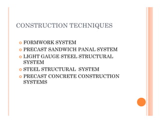
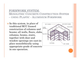
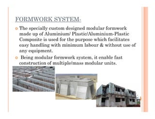
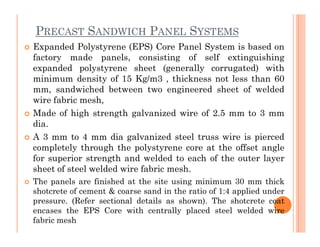
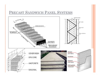
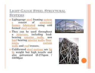
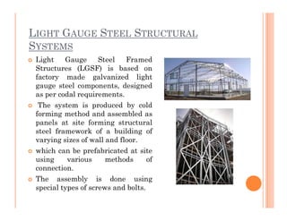
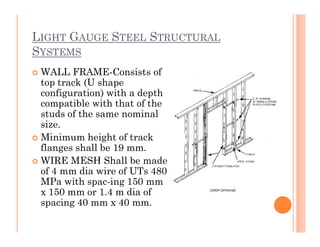
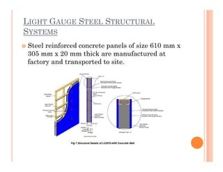
EMERGING TECHNOLOGIES FOR
MASS HOUSING
HOUSING
ASSIGNMENT-2
SUBMITTED BY-
RAJIT KUMAR
170040020
SEM-VII , 2K17
B.ARCHITECTURE
SUBMITTED TO-
AR.KAPIL ARORA
CONSTRUCTION TECHNIQUES
 FORMWORK SYSTEM
 PRECAST SANDWICH PANAL SYSTEM
 LIGHT GAUGE STEEL STRUCTURAL
SYSTEMSYSTEM
 STEEL STRUCTURAL SYSTEM
 PRECAST CONCRETE CONSTRUCTION
SYSTEMS
FORMWORK SYSTEM-
MONOLITHIC CONCRETE CONSTRUCTION SYSTEM
– USING PLASTIC - ALUMINIUM FORMWORK
 In this system, in place of
traditional RCC framed
construction of columns and
beams; all walls, floors, slabs,
columns, beams, stairs,
together with door and
window openings are cast-in-
place monolithically using
appropriate grade of concrete
in one operation.
FORMWORK SYSTEM-
 The specially custom designed modular formwork
made up of Aluminium/ Plastic/Aluminium-Plastic
Composite is used for the purpose which facilitates
easy handling with minimum labour & without use of
any equipment.
 Being modular formwork system, it enable fast Being modular formwork system, it enable fast
construction of multiple/mass modular units.
OTHER FEATURE
 Pre designed formwork acts as assembly line production and
enables rapid construction of multiple/mass scale units of
repetitive type.
 Varying work cycle is possible, however, for speed and
economy, 3 to 4 days cycle are desirable.
 It is flexible in design and can form any architectural or
structural configuration, such as stairs, windows, etc.
LimitationLimitation
 A lead time of about 3 months is required for initiation of
work, as the formwork are custom designed, manufactured
and prototype approved before manufacturing required
number of sets of formwork.
 Capital cost to initiate construction is high and may require
regular flow of funds.
 Post construction alterations are difficult.
 All the service lines are to be pre-planned in advance.
 Not much saving in construction in one storey structure
MONOLITHIC CONCRETE CONSTRUCTION
SYSTEM – USING ALUMINIUM FORMWORK
 The formwork systems used are made of light
weight Aluminium.
 The recommended concrete forms generally use
robotics welding system for manufacturing.
 A soft alloy weld wire is utilized in the concrete A soft alloy weld wire is utilized in the concrete
form weld process.
 Fixing of the formwork is done using tie, pin &
wedges system. Does not require very skilled
labour to do the job.
 The formwork can be designed based on
requirements of dwelling unit and the project. A
repetition of about 1000 cycle is claimed.
STRUCTURAL REQUIREMENTS OF THE
CONSTRUCTION
 The Monolithic RCC construction is considered as
shear wall system.
 The maximum spacing between cross wall shall be
limited to 1.5 times the floor height if supported on
two edges and 2.0 times the floor height, when
supported on all four edges.supported on all four edges.
 The walls are designed primarily for loading and also
for in-plane lateral load (shear) and out of plane
(bending) due to wind load and earthquake forces .
 Thickness of the wall is generally 100 mm with the
centrally placed reinforcement. Therefore, adequate
cover is likely to be maintained, as a result high
durability is achieved.
SISMO BUILDING TECHNOLOGY
 Sismo Building Technology is an
insulating shuttering kit for
whole building based on a three-
dimensional lattice made of
galvanized steel wire.
 The lattice is filled with
materials of different nature tomaterials of different nature to
serve as formwork. The basic
structure of the Sismo building
module is steel wire lattice.
 At the exterior sides of the
lattice, infill panels are inserted,
which transform the lattice into
a closed structure that can be
filled with concrete.
SISMO BUILDING TECHNOLOGY
 Description of the components is as follows:
 3D lattice (2.2 mm Ø galvanized steel wire)
 Infill panels (EPS, rock wool, mineral board)
 Structural filler (concrete)
 Finishing (plastering, natural stone, paneling
etc.)etc.)
SISMO BUILDING TECHNOLOGY
 Steel Lattice The steel wire frame, formwork for
the walls, are available in panels of different
dimensions as follows:
 Height: in multiples of 150 mm, with a max. of
12 m
 Length: in multiples of 100 mm, with a max. of Length: in multiples of 100 mm, with a max. of
1.2 m
 Thickness: Max. 500 mm, depending on the type
of wall /roof required
SISMO BUILDING TECHNOLOGY
 Functions of steel lattice The steel wire lattice
has the following basic functions:
 (i) To resist hydraulic pressure of fresh concrete
during pouring and first hours of hardening
 (ii) To keep reinforcement bars in place during
pouring of concretepouring of concrete
 (iii) To ensure adhesion (and reinforcement) of
finishing when using mineral based renders
PRECAST SANDWICH PANEL SYSTEMS
 Expanded Polystyrene (EPS) Core Panel System is based on
factory made panels, consisting of self extinguishing
expanded polystyrene sheet (generally corrugated) with
minimum density of 15 Kg/m3 , thickness not less than 60
mm, sandwiched between two engineered sheet of welded
wire fabric mesh,
 Made of high strength galvanized wire of 2.5 mm to 3 mm
dia.dia.
 A 3 mm to 4 mm dia galvanized steel truss wire is pierced
completely through the polystyrene core at the offset angle
for superior strength and welded to each of the outer layer
sheet of steel welded wire fabric mesh.
 The panels are finished at the site using minimum 30 mm thick
shotcrete of cement & coarse sand in the ratio of 1:4 applied under
pressure. (Refer sectional details as shown). The shotcrete coat
encases the EPS Core with centrally placed steel welded wire
fabric mesh
PRECAST SANDWICH PANEL SYSTEMS
RAPID PANELS
 The Rapid Panel is a prefabricated
assembly of high-strength steel
wire forming a panel with a core of
expanded polystyrene (EPS).
 During construction, Rapid
Panels are installed as walls
and/or slabs. Specified mixtures ofand/or slabs. Specified mixtures of
mortar or concrete are applied to
the surfaces of the panels to
complete the structure.
 The basic unit of the Rapid Panel
is the zig-zag truss. Steel wire is
bent into a zig-zag shape to form a
continuous chain of web members.
RAPID PANELS
RAPID PANELS
RAPID PANELS
 Construction process on site
LIGHT GAUGE STEEL STRUCTURAL
SYSTEMS
 Lightgauge steel framing system
s consist of structural
frames fabricated using cold
formed steel sections.
 They can be used throughout
a structure, including load-
bearing exterior walls, nonbearing exterior walls, non
load bearing interior walls, floor
joists, curtain
walls and roof trusses.
 Coldformed steel sections are lig
ht weight but high tensile and
also galvanized (Z-275gsm /
550Mpa)
LIGHT GAUGE STEEL STRUCTURAL
SYSTEMS
 Light Gauge Steel Framed
Structures (LGSF) is based on
factory made galvanized light
gauge steel components, designed
as per codal requirements.
 The system is produced by cold
forming method and assembled asforming method and assembled as
panels at site forming structural
steel framework of a building of
varying sizes of wall and floor.
 which can be prefabricated at site
using various methods of
connection.
 The assembly is done using
special types of screws and bolts.
LIGHT GAUGE STEEL STRUCTURAL
SYSTEMS
 WALL FRAME-Consists of
top track (U shape
configuration) with a depth
compatible with that of the
studs of the same nominal
size.size.
 Minimum height of track
flanges shall be 19 mm.
 WIRE MESH Shall be made
of 4 mm dia wire of UTs 480
MPa with spac-ing 150 mm
x 150 mm or 1.4 m dia of
spacing 40 mm x 40 mm.
LIGHT GAUGE STEEL STRUCTURAL
SYSTEMS
 Steel reinforced concrete panels of size 610 mm x
305 mm x 20 mm thick are manufactured at
factory and transported to site.
LIGHT GAUGE STEEL STRUCTURAL
SYSTEMS
 These panels are fixed on
either side of the LGSFS
wall using self-
drilling/tapping screws to
act as outer and inner facesact as outer and inner faces
of the wall leaving a gap
between them.
 This gap is then filled with
light weight concrete using
as pecial mixing and
pumping machine
PRECAST CONCRETE CONSTRUCTION
SYSTEMS
 Industrialized 3-S System using cellular light
weight concrete slabs & precast columns: This
technology is being used since 1972, and is based on
industrial unit mass manufactured structural
prefab components meeting the requirements ofprefab components meeting the requirements of
Indian Standards. The major precast elements
are:RCC hollow columns with notches
 RCC solid beams (T/L/Square Shape)
 Staircase
 RCC precast slab
 AAC precast slab
 AAC precast block
PRECAST CONCRETE CONSTRUCTION
SYSTEMS
 The surface of each panel consists of 51 mm thick
slab or skin, stiffened with the ribs around the
perimeter and across the panel, giving an overall
panel thickness of 152 mm or 203mm.
PRECAST CONCRETE CONSTRUCTION
SYSTEMS
STEEL STRUCTURAL SYSTEMS
 Speed floor system: These are suspended
concrete flooring system using a roll formed steel
joist as an essential part of the final concrete and
steel composite floor. An integrated continuous
one-way slab and a hybrid concrete/steel tee-
beam in other direction.beam in other direction.
 .
STEEL STRUCTURAL SYSTEMS
 The joist is Galvanized steelSize may be any one
of the following i.e. 200mm, 250mm, 300mm,
350mm and 400mm,
 depending upon the design requirements.
Concrete thickness may be 75mm or 90mm as
requiredrequired
STEEL STRUCTURAL SYSTEMS
 Limitations-The system is used as framed steel
structure in all types of construction forlaying
RCC roof. Maximum length of joist which can be
used is 10m.
 Edge angles -A standard edge form is available
in two heights – 75mm & 90mm.Special heights
and specially shaped edge angles may beand specially shaped edge angles may be
manufactured but would require longer lead
times.
 Jointers-Precut sections of galvanized sheet
steel may be provided to overlay joints in the ply
to ensure they are flush and remain well
supported while the concrete is poured.
FEFERENCE-
 https://www.nbmcw.com/tech-articles/precast-
construction/42137-prefabrication-building-
construction-an-indian-perspective.html
 http://mohua.gov.in/cms/BMTPC.php
THANK YOU

Assignment 2 (techniqes construction of mass building)

  • 1.
    EMERGING TECHNOLOGIES FOR MASSHOUSING HOUSING ASSIGNMENT-2 SUBMITTED BY- RAJIT KUMAR 170040020 SEM-VII , 2K17 B.ARCHITECTURE SUBMITTED TO- AR.KAPIL ARORA
  • 2.
    CONSTRUCTION TECHNIQUES  FORMWORKSYSTEM  PRECAST SANDWICH PANAL SYSTEM  LIGHT GAUGE STEEL STRUCTURAL SYSTEMSYSTEM  STEEL STRUCTURAL SYSTEM  PRECAST CONCRETE CONSTRUCTION SYSTEMS
  • 3.
    FORMWORK SYSTEM- MONOLITHIC CONCRETECONSTRUCTION SYSTEM – USING PLASTIC - ALUMINIUM FORMWORK  In this system, in place of traditional RCC framed construction of columns and beams; all walls, floors, slabs, columns, beams, stairs, together with door and window openings are cast-in- place monolithically using appropriate grade of concrete in one operation.
  • 4.
    FORMWORK SYSTEM-  Thespecially custom designed modular formwork made up of Aluminium/ Plastic/Aluminium-Plastic Composite is used for the purpose which facilitates easy handling with minimum labour & without use of any equipment.  Being modular formwork system, it enable fast Being modular formwork system, it enable fast construction of multiple/mass modular units.
  • 5.
    OTHER FEATURE  Predesigned formwork acts as assembly line production and enables rapid construction of multiple/mass scale units of repetitive type.  Varying work cycle is possible, however, for speed and economy, 3 to 4 days cycle are desirable.  It is flexible in design and can form any architectural or structural configuration, such as stairs, windows, etc. LimitationLimitation  A lead time of about 3 months is required for initiation of work, as the formwork are custom designed, manufactured and prototype approved before manufacturing required number of sets of formwork.  Capital cost to initiate construction is high and may require regular flow of funds.  Post construction alterations are difficult.  All the service lines are to be pre-planned in advance.  Not much saving in construction in one storey structure
  • 6.
    MONOLITHIC CONCRETE CONSTRUCTION SYSTEM– USING ALUMINIUM FORMWORK  The formwork systems used are made of light weight Aluminium.  The recommended concrete forms generally use robotics welding system for manufacturing.  A soft alloy weld wire is utilized in the concrete A soft alloy weld wire is utilized in the concrete form weld process.  Fixing of the formwork is done using tie, pin & wedges system. Does not require very skilled labour to do the job.  The formwork can be designed based on requirements of dwelling unit and the project. A repetition of about 1000 cycle is claimed.
  • 7.
    STRUCTURAL REQUIREMENTS OFTHE CONSTRUCTION  The Monolithic RCC construction is considered as shear wall system.  The maximum spacing between cross wall shall be limited to 1.5 times the floor height if supported on two edges and 2.0 times the floor height, when supported on all four edges.supported on all four edges.  The walls are designed primarily for loading and also for in-plane lateral load (shear) and out of plane (bending) due to wind load and earthquake forces .  Thickness of the wall is generally 100 mm with the centrally placed reinforcement. Therefore, adequate cover is likely to be maintained, as a result high durability is achieved.
  • 8.
    SISMO BUILDING TECHNOLOGY Sismo Building Technology is an insulating shuttering kit for whole building based on a three- dimensional lattice made of galvanized steel wire.  The lattice is filled with materials of different nature tomaterials of different nature to serve as formwork. The basic structure of the Sismo building module is steel wire lattice.  At the exterior sides of the lattice, infill panels are inserted, which transform the lattice into a closed structure that can be filled with concrete.
  • 9.
    SISMO BUILDING TECHNOLOGY Description of the components is as follows:  3D lattice (2.2 mm Ø galvanized steel wire)  Infill panels (EPS, rock wool, mineral board)  Structural filler (concrete)  Finishing (plastering, natural stone, paneling etc.)etc.)
  • 10.
    SISMO BUILDING TECHNOLOGY Steel Lattice The steel wire frame, formwork for the walls, are available in panels of different dimensions as follows:  Height: in multiples of 150 mm, with a max. of 12 m  Length: in multiples of 100 mm, with a max. of Length: in multiples of 100 mm, with a max. of 1.2 m  Thickness: Max. 500 mm, depending on the type of wall /roof required
  • 11.
    SISMO BUILDING TECHNOLOGY Functions of steel lattice The steel wire lattice has the following basic functions:  (i) To resist hydraulic pressure of fresh concrete during pouring and first hours of hardening  (ii) To keep reinforcement bars in place during pouring of concretepouring of concrete  (iii) To ensure adhesion (and reinforcement) of finishing when using mineral based renders
  • 12.
    PRECAST SANDWICH PANELSYSTEMS  Expanded Polystyrene (EPS) Core Panel System is based on factory made panels, consisting of self extinguishing expanded polystyrene sheet (generally corrugated) with minimum density of 15 Kg/m3 , thickness not less than 60 mm, sandwiched between two engineered sheet of welded wire fabric mesh,  Made of high strength galvanized wire of 2.5 mm to 3 mm dia.dia.  A 3 mm to 4 mm dia galvanized steel truss wire is pierced completely through the polystyrene core at the offset angle for superior strength and welded to each of the outer layer sheet of steel welded wire fabric mesh.  The panels are finished at the site using minimum 30 mm thick shotcrete of cement & coarse sand in the ratio of 1:4 applied under pressure. (Refer sectional details as shown). The shotcrete coat encases the EPS Core with centrally placed steel welded wire fabric mesh
  • 13.
  • 14.
    RAPID PANELS  TheRapid Panel is a prefabricated assembly of high-strength steel wire forming a panel with a core of expanded polystyrene (EPS).  During construction, Rapid Panels are installed as walls and/or slabs. Specified mixtures ofand/or slabs. Specified mixtures of mortar or concrete are applied to the surfaces of the panels to complete the structure.  The basic unit of the Rapid Panel is the zig-zag truss. Steel wire is bent into a zig-zag shape to form a continuous chain of web members.
  • 15.
  • 16.
  • 17.
  • 18.
    LIGHT GAUGE STEELSTRUCTURAL SYSTEMS  Lightgauge steel framing system s consist of structural frames fabricated using cold formed steel sections.  They can be used throughout a structure, including load- bearing exterior walls, nonbearing exterior walls, non load bearing interior walls, floor joists, curtain walls and roof trusses.  Coldformed steel sections are lig ht weight but high tensile and also galvanized (Z-275gsm / 550Mpa)
  • 19.
    LIGHT GAUGE STEELSTRUCTURAL SYSTEMS  Light Gauge Steel Framed Structures (LGSF) is based on factory made galvanized light gauge steel components, designed as per codal requirements.  The system is produced by cold forming method and assembled asforming method and assembled as panels at site forming structural steel framework of a building of varying sizes of wall and floor.  which can be prefabricated at site using various methods of connection.  The assembly is done using special types of screws and bolts.
  • 20.
    LIGHT GAUGE STEELSTRUCTURAL SYSTEMS  WALL FRAME-Consists of top track (U shape configuration) with a depth compatible with that of the studs of the same nominal size.size.  Minimum height of track flanges shall be 19 mm.  WIRE MESH Shall be made of 4 mm dia wire of UTs 480 MPa with spac-ing 150 mm x 150 mm or 1.4 m dia of spacing 40 mm x 40 mm.
  • 21.
    LIGHT GAUGE STEELSTRUCTURAL SYSTEMS  Steel reinforced concrete panels of size 610 mm x 305 mm x 20 mm thick are manufactured at factory and transported to site.
  • 22.
    LIGHT GAUGE STEELSTRUCTURAL SYSTEMS  These panels are fixed on either side of the LGSFS wall using self- drilling/tapping screws to act as outer and inner facesact as outer and inner faces of the wall leaving a gap between them.  This gap is then filled with light weight concrete using as pecial mixing and pumping machine
  • 23.
    PRECAST CONCRETE CONSTRUCTION SYSTEMS Industrialized 3-S System using cellular light weight concrete slabs & precast columns: This technology is being used since 1972, and is based on industrial unit mass manufactured structural prefab components meeting the requirements ofprefab components meeting the requirements of Indian Standards. The major precast elements are:RCC hollow columns with notches  RCC solid beams (T/L/Square Shape)  Staircase  RCC precast slab  AAC precast slab  AAC precast block
  • 24.
    PRECAST CONCRETE CONSTRUCTION SYSTEMS The surface of each panel consists of 51 mm thick slab or skin, stiffened with the ribs around the perimeter and across the panel, giving an overall panel thickness of 152 mm or 203mm.
  • 25.
  • 26.
    STEEL STRUCTURAL SYSTEMS Speed floor system: These are suspended concrete flooring system using a roll formed steel joist as an essential part of the final concrete and steel composite floor. An integrated continuous one-way slab and a hybrid concrete/steel tee- beam in other direction.beam in other direction.  .
  • 27.
    STEEL STRUCTURAL SYSTEMS The joist is Galvanized steelSize may be any one of the following i.e. 200mm, 250mm, 300mm, 350mm and 400mm,  depending upon the design requirements. Concrete thickness may be 75mm or 90mm as requiredrequired
  • 28.
    STEEL STRUCTURAL SYSTEMS Limitations-The system is used as framed steel structure in all types of construction forlaying RCC roof. Maximum length of joist which can be used is 10m.  Edge angles -A standard edge form is available in two heights – 75mm & 90mm.Special heights and specially shaped edge angles may beand specially shaped edge angles may be manufactured but would require longer lead times.  Jointers-Precut sections of galvanized sheet steel may be provided to overlay joints in the ply to ensure they are flush and remain well supported while the concrete is poured.
  • 29.