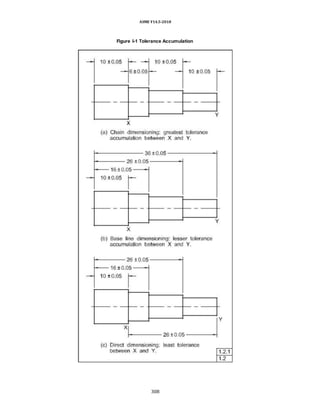
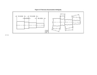
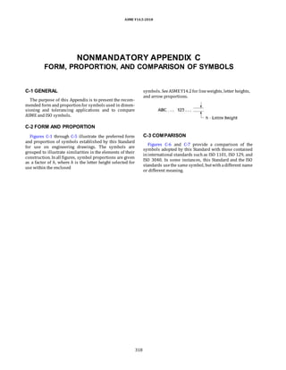
The document describes ASME Y14.5-2018, which is an international standard for dimensioning and tolerancing engineering drawings. It was revised from the 2009 version. The standard provides rules for dimensioning features, tolerancing, interpreting limits, and using related symbology on drawings. It is adopted by the Department of Defense and other military and industrial organizations for product definition and documentation.


![ASME Y14.5-2018
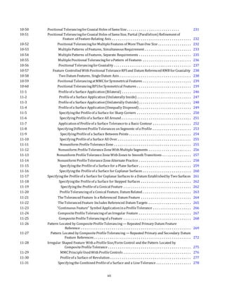
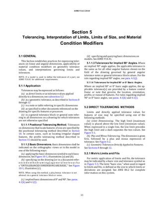
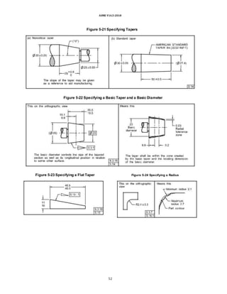
(a) a basictaper and a basic diameter (see Figure 5-22)
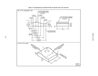
(b) a sizetolerancecombinedwitha profileof a
surfacetolerance appliedto the taper (see para. 11.4.2)
(c) a toleranced diameter at both ends of a taper and a
toleranced length [seeFigure 5-21, illustration(a)]
NOTE: The method described in (c) above is applicable for
noncritical tapers, such as the transition between diameters of a
shaft.
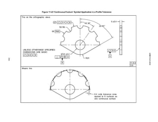
(d) a compositeprofiletolerance
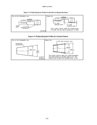
Conical taper is the ratio of the difference in the
diameters of two sections (perpendicular to the axis) of a
cone to the distance between these sections.
Thus, taper = (D − d)/L in the followingdiagram:
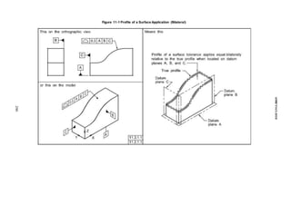
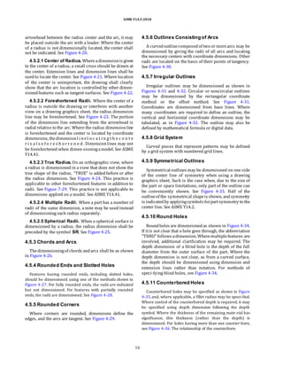
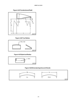
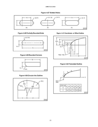
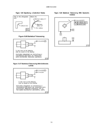
5.16.2 Controlled Radius Tolerance
When a controlled radius is specified, a tolerance zone
bounded by two arcs is created (the minimum and maximum
radii). The part surface shall be within this tolerance zone
and shall be a fair curve without reversals. Additionally, radii
taken at all points on the part contour shall be neither
smaller than the specified minimum limit nor larger than the
maximum limit. See Figure 5-25. When the center of the
radius is located via dimension(s), the arcs are concentric.
When the center of the radius is not located (tangent
located), the arcs are tangent to the adja-cent surfaces and
create a crescent-shaped tolerance zone.
NOTE: It is recommended that the controlled radius only be
used if its meaning is clarified by a general note, a company or
industry standard, or another engineering specification. This
clarification should define the limits of allowable imperfections,
and should be referenced on the drawing, annotated model, or
elsewhere in the data set.
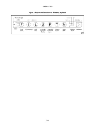
Thesymbol foraconical taper is shownin Figure 5-22.
5.15 FLAT TAPERS
A flat taper may be specified by a toleranced slope and
a toleranced height at one end. See Figure 5-23. Slope
may be specifiedas the inclination of a surface expressed
as a ratio of the difference in the heights at each end
(above and at right angles to a base line) to the distance
between those heights.
Thus, slope=(H − h)/L inthe followingdiagram:
Thesymbol forslopeis shownin Figure5-23.
5.16 RADIUS
When a radius is specified, the details in paras. 5.16.1
and 5.16.2 shall apply.
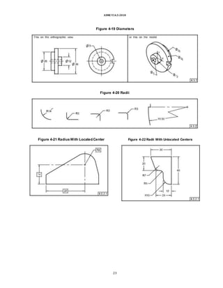
5.16.1 Directly Toleranced Radius
When a radius symbol R is specified, a tolerance zone
bounded by two arcs is created (the minimum and
maximum radii). The part surface shall be within this
zone. When the center of the radius is located via dimen-
sion(s), the arcs are concentric. When the center of the
radius is not located (tangent located), the arcs are
tangent to the adjacent surfaces and create a crescent-
shaped tolerance zone. See Figure 5-24.
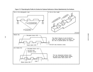
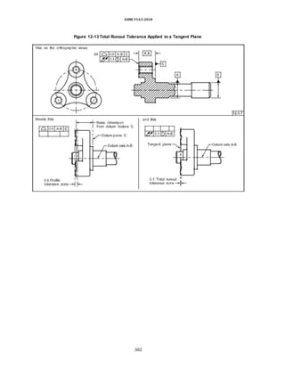
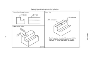
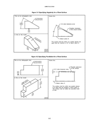
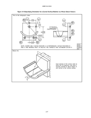
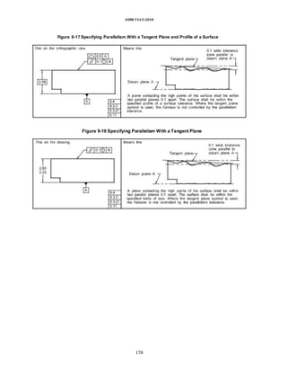
5.17 TANGENT PLANE
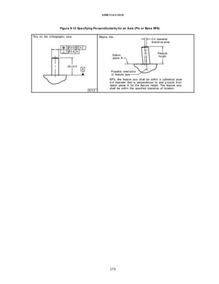
When it is desired to control a tangent plane
established by the contacting points of a surface, the
tangent plane symbol shall be added in the feature
control frame after the stated tolerance. See Figures 9-17
and 9-18. Where irregularities on the surface cause the
tangent plane to be unstable (i.e., it rocks) when brought
into contact with the corresponding toleranced feature,
see para. 7.11.2 and ASME Y14.5.1M.
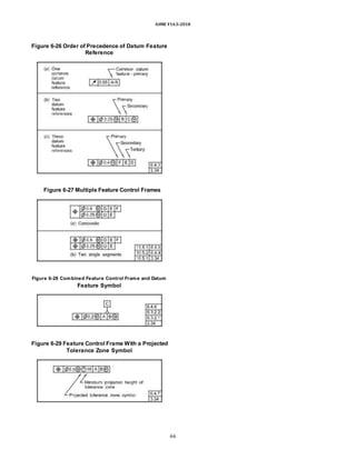
5.18 STATISTICAL TOLERANCING
When itis the choiceof the design activity to usestatis-
tical tolerancing, it may be indicated in the following
manner. See Figures 5-26 through 5-28.
(a) A note suchas the followingshall beplacedonthe
d r a wi n g : F E A T U R E S I D E N T I F I E D W I T
H T H E STATISTICALLY TOLERANCED SYMBOL
SHALL BE PRODUCED WITH STATISTICAL
PROCESS CONTROLS. See Figure 5-26.
(b) When it is necessary to designate both the statistical
limits and the arithmetic limits where the dimension has the
possibility of being produced without statistical process
control (SPC),a note such as the following shall be placed on
the drawing: FEATURES IDENTIFIED
WITH THE STATISTICALLY TOLERANCED SYMBOL
SHALL BE PRODUCED WITH STATISTICAL PROCESS
CONTROLS, OR TO THE MORE RESTRICTIVE
ARITHMETIC LIMITS. See Figure 5-27.
CAUTION: When using the “statistical tolerancing” symbol,
the necessary statistical indices should be specified.
39](https://image.slidesharecdn.com/asme-y14-220624140424-f03d2f14/85/ASME-Y14-5-2018-Dimensioning-and-Tolerancing-Copy-doc-57-320.jpg)

![ASME Y14.5-2018
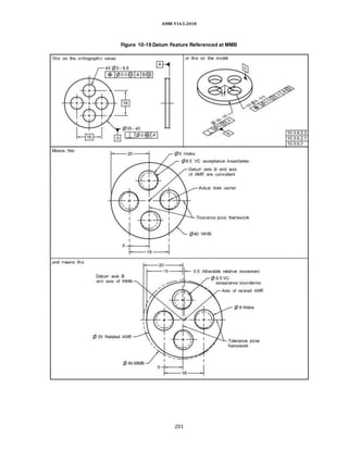
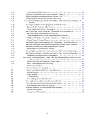
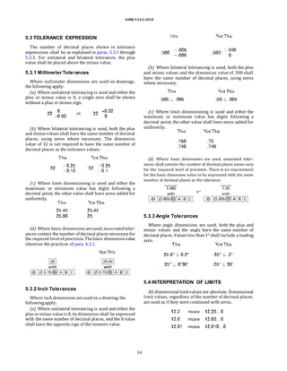
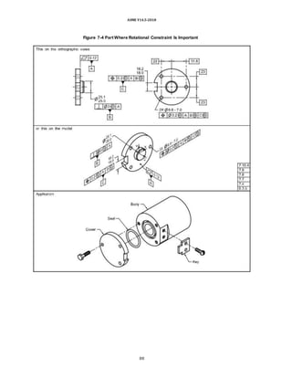
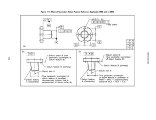
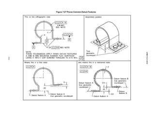
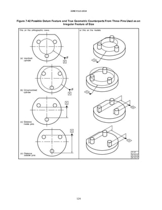
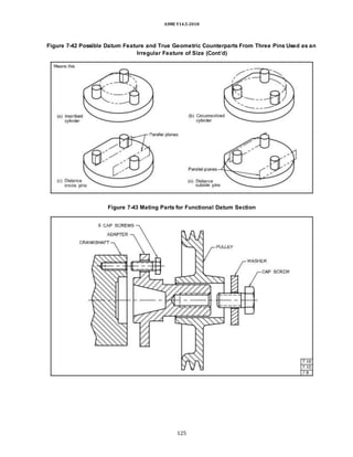
7.11.4 Datum Features Applicable RMB
When a datum feature or collection of datum features
applies RMB in a feature control frame, the true
geometric counterpart geometry originates at the MMB
and progresses proportionally through the tolerance
zone to make maximum possible contact with the datum
feature or collection of features. If another fitting routine
is required, it shall be stated on the drawing.
As a practical example, a machine element that is vari-
able (suchas a chuck, mandrel, vise, or centering device)
is used as a physical datum feature simulator of the
datum feature and to establish the simulated datum.
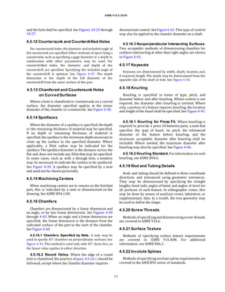
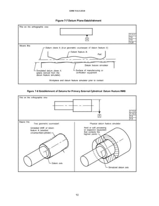
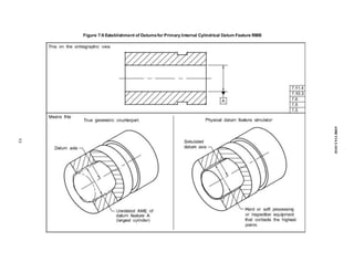
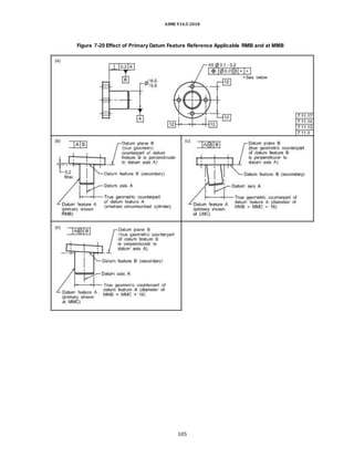
(a) Primary Datum Feature — Cylinder RMB. The datum is
the axis of the true geometric counterpart of the datum
feature. The true geometric counterpart (or unrelated AME)
is the smallest circumscribed (for an external feature) or
largest inscribed (for an internal feature) perfect cylinder
that makes maximum possible contact with the datum
feature surface. See Figure 7-3, illustration
(d) and Figures 7-8 and 7-9.
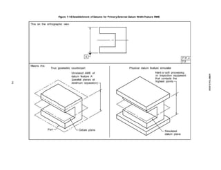
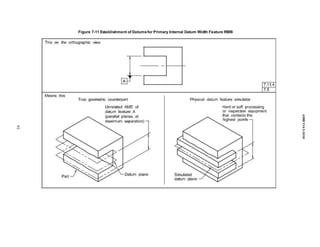
(b) Primary Datum Feature — Width RMB. The datum is
the center plane of the true geometric counterpart of the
datum feature. The true geometric counterpart (or unre-
lated AME) is two parallel planes at minimum separation
(for an external feature) or maximum separation (for an
internal feature) that make maximum possible contact with
the corresponding surfaces of the datum feature. See Figure
7-3, illustration (b) and Figures 7-10 and 7-11.
(c) Primary Datum Feature — Sphere RMB. The datum is
the center point of the true geometric counterpart of the
datum feature. The true geometric counterpart (or unre-
lated AME) is the smallest circumscribed (for an external
feature) or largest inscribed (for an internal feature) perfect
sphere that makes maximum possible contact with the
datum feature surface. See Figure 7-3, illustration
(c).
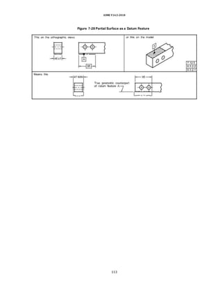
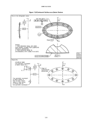
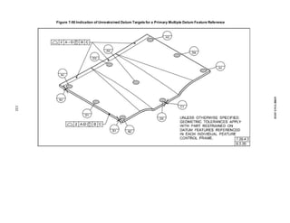
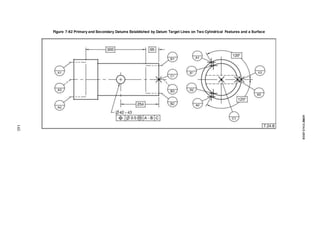
(d) Primary Datum Feature — Complex Features RMB.
Simulation of a complex feature referenced as primary
RMB may resultina difficultsimulationrequirement. For
these applications, the specification of datum targets; a
datum feature referenced at [BSC], with the abbreviation
“BSC” meaning basic; or an alternatively defined
stabilization method may be used. See Figure 7-29.
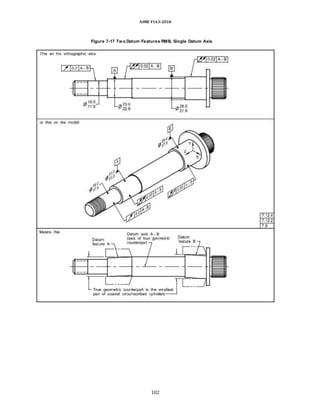
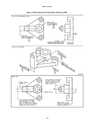
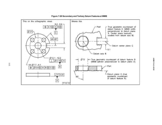
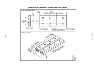
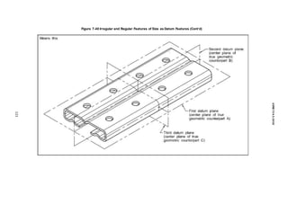
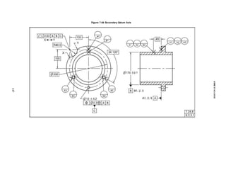
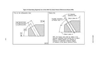
(e) Secondary Datum Feature RMB — Cylinder or
Width. For both external and internal features, the
secondary datum (axis or center plane) is established in
the same manner as indicated in (a) and (b) with an
additional requirement. The theoretical cylinder or
parallel planes of the true geometric counterpart shall be
oriented and/or located to the primary datum feature’s
true geometric counterpart. Datum feature B in Figure 7-
21 illustrates this principleforcylinders, and Figure 7-38
illustrates the same principle for widths. In Figure 7-38,
the secondary true geometric counterpart RMB
expands and makes maximum possible contact,
constraining all possible remaining degrees of freedom.
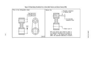
(f) Tertiary Datum Feature — Cylinder or Width RMB.
For both external and internal features, the tertiary
datum (axis or center plane) is established in the same
manner as indicated in (e) with an additional
requirement. The theo-retical cylinder or parallel planes
of the true geometric counterpart shall be oriented
and/or located to both the primary and secondary datum
features’ true geometric counterparts. A width tertiary
datum feature may belocated to a datum axis as in Figure
7-21 or offset from a plane of the datum reference frame.
Figure 7-6 illustrates the same principle for a cylinder.
(g) Secondary and Tertiary Datum Features — Sphere
RMB. The secondary or tertiary datum (center point) is
established in the same manner as indicated in (c) with
an additional requirement that the theoretical center
point is located relative to higher-precedence datum
features’ true geometric counterparts. The true geometric
counterpart for a translatable secondary or tertiary
spherical datum feature is established in the same
manner as for a primary one as stated in (c).
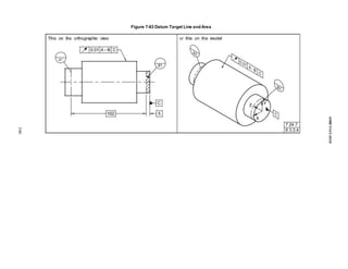
(h) Secondary and Tertiary Surfaces RMB. Where the
datum feature (secondary or tertiary) is a surface, RMB
applied to the datum feature requires the true geometric
counterpart to expand, contract, or progress normal to
the true profile of the feature from its MMB to its LMB
until the true geometric counterpart makes maximum
possible contact with the extremities of the datum
feature whilerespectingthe higher-precedence datum(s).
See Figures 7-30, 7-32, and 7-34.
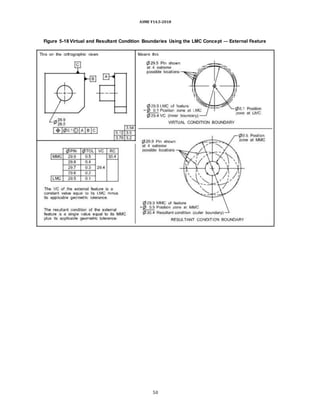
7.11.5 Specifying Datum Features at MMB
Where MMB is applied to a datum feature referenced
in a feature control frame, it establishes the true
geometric counterpart of the appropriate boundary. The
appropriate boundary is determined by the collective
effects of size and any applicable geometric tolerances
relative to any higher-precedence datums. As a practical
example, when a datum feature is applied on an MMB
basis, machine and gaging elements in the processing
equipment that remain constant may be used to simulate
a true geometric counterpart of the feature and to
establish the simulated datum. To determine the
applicable boundary, see para. 7.11.6.
7.11.6 Determining the Size of True
Geometric Counterparts at MMB
An analysis of geometric tolerances applied to a datum
feature is necessary in determining the size of the datum
feature’s true geometric counterpart. A feature of size or a
pattern of features of size serving as a datum feature may
have several MMBs. These include the MMC of a datum
feature of size and the collective effects of MMC and
geometric tolerances. Datum feature precedence shall
74](https://image.slidesharecdn.com/asme-y14-220624140424-f03d2f14/85/ASME-Y14-5-2018-Dimensioning-and-Tolerancing-Copy-doc-92-320.jpg)
![ASME Y14.5-2018
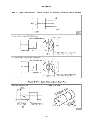
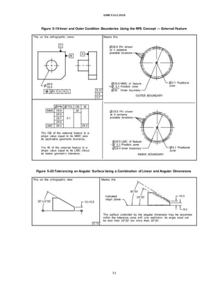
7.11.9 Specifying Datum Features RMB
Where RFS is applicable to the tolerances applied to a
datum feature and RMB is applicable to the datum
feature reference in a feature control frame, there is no
fixed-sizetrue geometric counterpart. The true geometric
counter-part shall contract to fit an external datum
feature and expand to fit an internal datum feature. For
an external feature, there is a maximum external
boundary that is the collective effects of size, form, and
any applicable geometric tolerances relative to any
higher-precedence datums. For an internal feature, there
is a minimum internal boundary that is the collective
effects of size, form, and any applicable geometric
tolerances relative to any higher-precedence datums. As
a practical example, where a datum feature of size is
appliedon an RMB basis, machineandgaging elements in
the process equipmentshall beable to expand or contract
as required to establish the simulated datum. To deter-
mine the applicable boundary, see para. 7.11.9.1.
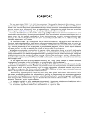
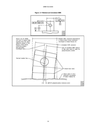
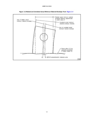
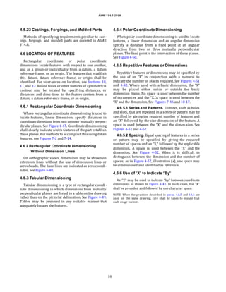
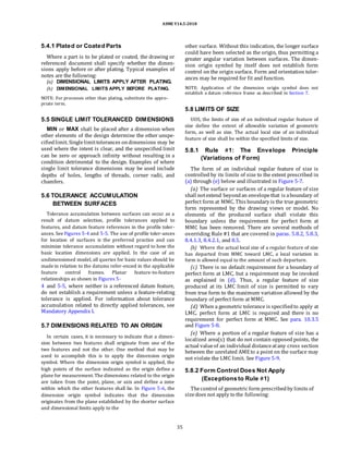
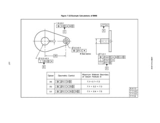
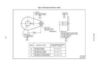
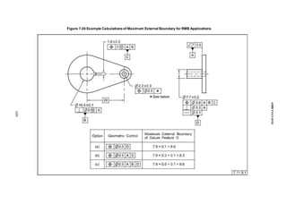
7.11.9.1 Determining a Worst-Case Material
Boundary (RMB). Datum feature D in Figure 7-24 has
three OBs resulting from the tolerances applied to the
datum feature and the datum reference applied RMB. For
an external feature of size, the maximum OB is the
smallestenvelopethat the datum feature does not violate
with that envelope constrained to any higher-precedence
datums.
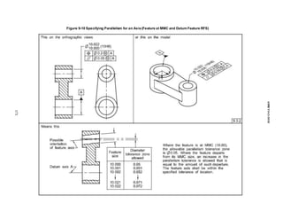
(a) Where datum feature D is referenced as primary,
collective effects of MMC (7.9 dia.) and the straightness
tolerance (0.1 dia.) establish an OB of 8 dia. See option
(a) inthe tableshownin Figure7-24.
(b) Where datum feature D is referenced as secondary,
to ensure that datum precedence is not violated, the
collec-tive effects of the MMC (7.9 dia.), the
perpendicularity tolerance(0.3 dia.), and the straightness
tolerance of 0.1dia. establish an OB of 8.3 dia. See option
(b) in the table shown in Figure 7-24.
(c) Where datum feature D is referenced as tertiary, to
ensure that datum precedence is not violated, the collec-
tive effects of the MMC (7.9 dia.), the position tolerance
(0.6dia.), and the straightness tolerance of 0.1 dia. estab-
lish an OB of 8.6 dia. Because straightness applied to a
feature of sizecontrols thederived medianline, and posi-
tion controls the axis of the unrelated AME, the form and
position tolerances accumulate. Since the perpendicu-
larity tolerance (0.3 dia.) is a refinement of the position
tolerance, it is not additive. See option (c) in the table
shown in Figure 7-24.
7.11.10 Explicit Specification of True
Geometric Counterpart Boundaries
In cases where the boundary is not clear or another
boundary is required, the value of a fixed-size boundary
shall be stated, enclosed in brackets, following the appli-
cable datum feature reference and any modifier, such as
the “free state” symbol, in the feature control frame. RMB,
MMB, and LMB are not applicable when the size of the
simulator is specified. The boundary may also be specified
by including a numeric value preceded by a diameter
symbol, radius symbol, spherical diameter, or spherical
radius symbol, as applicable, between the brackets.
To indicate that the true geometric counterpart is
defined by the basic dimensions of the true profile of the
datum feature, the term “[BSC],” meaning basic, shall
follow the datum reference letter in the feature control
frame. See Figure 7-35.
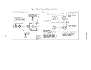
7.11.11 Datum Feature Shift/Displacement
MMB or LMB modifiers applied to the datum feature
reference allow the datum feature to shift/displace from
the boundary established by the true geometric
counterpart in an amount that is equal to the difference
between the applicable (unrelated or related) AME for
MMB, actual minimum material envelope for LMB, or
surface of the feature and the true geometric counterpart.
The datum reference frame is established from the true
geometric counterpart and not the datum features. See
Figure 7-25 for LMB; Figures 7-16, 7-18, and 7-26 for
MMB; and Figure 7-33 for a surface referenced as a
datum feature at MMB. The datum feature shift/displace-
ment shall always be limited or constrained by the true
geometric counterpart. Where the true geometric coun-
terpart geometry does not fully limit or constrain the
feature, such as where it may rotate away from the true
geometric counterpart as shown in Figure 7-36, an
extremity of the datum feature shall remain between the
MMB and the LMB. See para. 7.16.7.
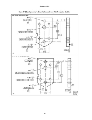
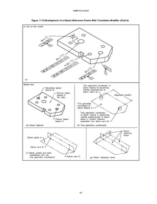
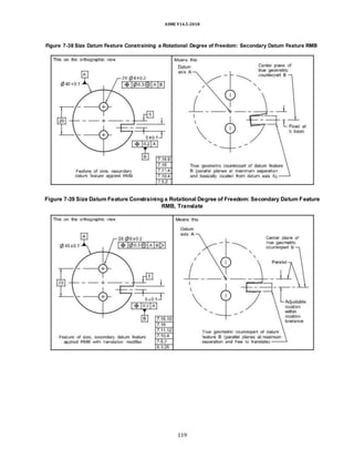
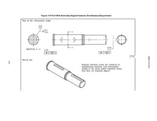
7.11.12 Translation Modifier
When it is necessary to indicate that the basic location of
the true geometric counterpart is unlocked and the true
geometric counterpart is able to translate within the speci-
fied geometric tolerance to fully engage the feature, the
translation modifier shall be added to the feature control
frame following the datum feature reference and any other
applicable modifiers. See Figure 7-12, illustration (a), Figure
7-39, and para. 6.3.26. When the translation modi-fier is
applicable and the direction of movement is not clear,
movement requirements shall be specified. A coor-dinate
system for the applicable datum reference frame is added
and the direction of movement is indicated using a unit
vector designation consisting of “i, j, k” components
(corresponding to the X-axis, Y-axis, and Z-axis of the coor-
dinate system), placed in brackets and following the trans-
lation modifier symbol. See Figure 7-12, illustrations (b)
76](https://image.slidesharecdn.com/asme-y14-220624140424-f03d2f14/85/ASME-Y14-5-2018-Dimensioning-and-Tolerancing-Copy-doc-94-320.jpg)
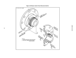
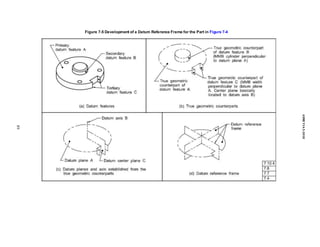
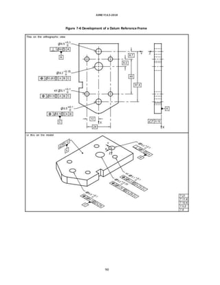
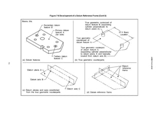
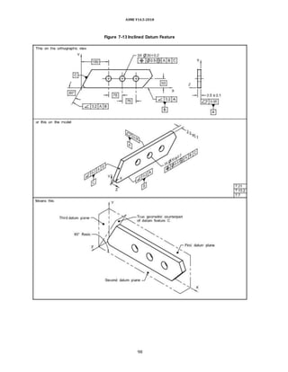
![ASME Y14.5-2018
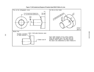
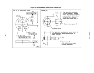
development of a datum reference frame based on the
principles outlined in the true geometric counterpart re-
quirements. In these figures, datum feature A establishes
an axis and the lower-precedence datum feature B is
located(positionedor profiled) to datum feature A and is
then used to orient the rotational degrees of freedom to
establishthe datum reference frame that is used to locate
the two 6-mm-dia. holes. Depending on functional
requirements, this lower-precedence datum feature may
apply RMB or be modified to apply at MMB or LMB. The
datum reference frame is established from the true
geometric counterparts and not from the datum features.
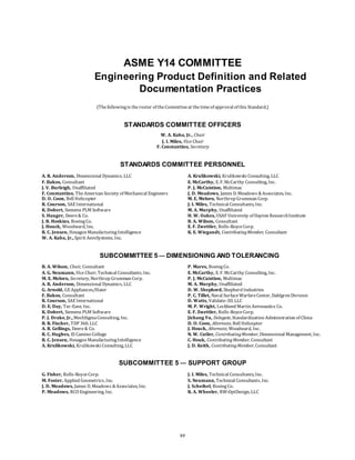
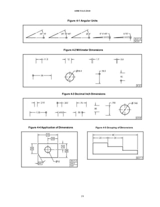
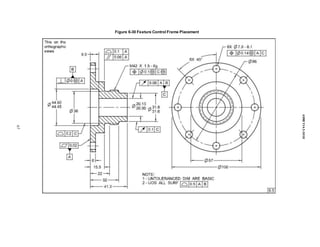
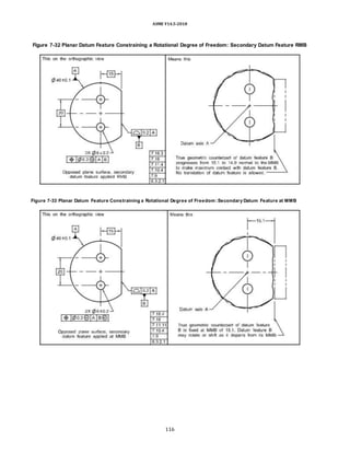
7.16.4 PlanarDatum Feature at MMB Constraining a
Rotational Degree of Freedom
In Figure 7-33, datum feature B is modified to apply at
MMB. This requires the true geometric counterpart to be
fixed at the MMB of 15.1 and thus orients the two planes
that originate at the axis of the true geometric
counterpart of datum feature A. Where datum feature B
departs from MMB, relative movement (rotation) can
occur between the true geometric counterpart for datum
feature B and the related AME of datum feature B. Datum
feature B may rotate within the confines created by its
departure from MMB and might not remain in contact
with the true geometric counterpart.
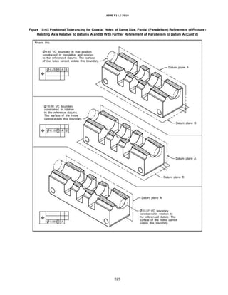
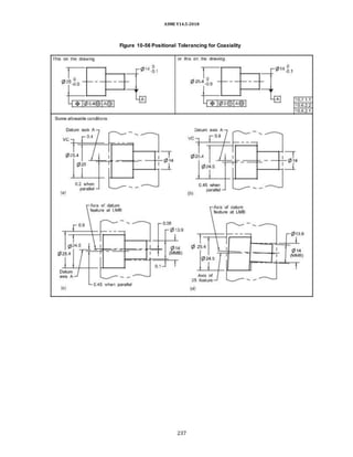
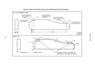
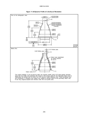
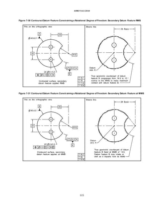
7.16.1 Contoured Datum Feature RMB
Constraining a Rotational Degree of
Freedom
In Figure 7-30, datum feature B applies RMB. This
requires the true geometric counterpart geometry to
originate at the MMB of R14.9 and progress through the
profile tolerance zone toward the LMB of R15.1 until it
makes maximum contact with datum feature B and
constrains the rotational degree of freedom of the part
around the axis of the true geometric counterpart from
datum feature A.
7.16.2 Contoured Datum Feature at MMB
Constraining a Rotational Degree of
Freedom
In Figure 7-31, datum feature B is modified to apply at
MMB. This requires the true geometric counterpart to be
fixedat the MMB of R14.9and thus orients the two planes
that originate at the axis of the true geometric
counterpart of datum feature A. Where datum feature B
departs from MMB, relative movement (rotation) can
occur between the true geometric counterpart for datum
feature B and the related AME of datum feature B. Datum
feature B may rotate within the confines created by its
departure from MMB and might not remain in contact
with the true geometric counterpart.
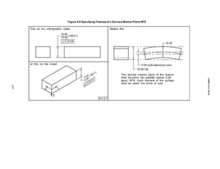
7.16.3 Planar Datum Feature RMB Constraining a
Rotational Degree of Freedom
In Figure 7-32, datum feature B applies RMB. This
requires the true geometric counterpart geometry to
originate at the MMB of 15.1 and progress through the
profile tolerance zone toward the LMB of 14.9 until it
makes maximum contact with datum feature B and
constrains the rotational degree of freedom of the part
around the axis of the true geometric counterpart of
datum feature A.
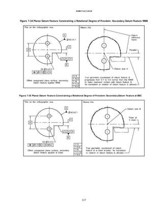
7.16.5 Offset Planar Datum Feature RMB
Constraining a RotationalDegree of
Freedom
In Figure 7-34, datum feature B is offset relative to
datum axis A and applies RMB. This requires the true
geometric counterpart to meet the following conditions:
(a) The true geometric counterpart geometry origi-
nates at the MMB of 5.1 and progresses through the
profile tolerance zone toward the LMB of 4.9 until it
makes maximum contact with datum feature B.
(b) The true geometric counterpart constrains the
rota-tional degree of freedom of the part around the axis
of the true geometric counterpart of datum feature A.
7.16.6 Offset Planar Datum Feature Set at Basic,
Constraining a RotationalDegree of
Freedom
In Figure 7-35, datum feature B is offset 5 relative to
datum axis A. RMB does not apply as it is overridden in
the feature control frame for the two holes by “[BSC]”
following the reference to datum feature B. See para.
7.11.10. This requires the true geometric counterpart to
be fixed at 5 basic and the datum feature shall make
contact with the true geometric counterpart. This
constrains the rotational degree of freedom of the two
planes of the datum reference frame around the axis of
the true geometric counterpart of datum feature A.
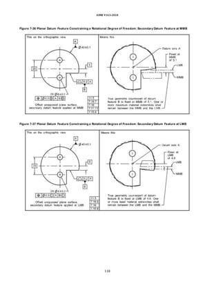
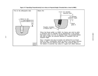
7.16.7 Offset Planar Datum Feature at MMB
Constraining a RotationalDegree of
Freedom
In Figure 7-36, datum feature B is offset relative to datum
axis A and the datum feature reference is modified to apply
at MMB. This requires the true geometric counter-part to be
fixed at the MMBof 5.1 and constrains the rota-tional degree
of freedom of the two planes of the datum reference frame
that originate at the true geometric coun-terpart of datum
feature A. The part may rotate on datum axis A provided one
or more maximum material
79](https://image.slidesharecdn.com/asme-y14-220624140424-f03d2f14/85/ASME-Y14-5-2018-Dimensioning-and-Tolerancing-Copy-doc-97-320.jpg)
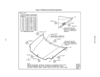
![ASME Y14.5-2018
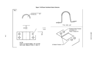
in accordance with the specified restraint requirement to
flex or deform the part. See Figure 7-52.
NOTE: The position tolerance shown in Figure 7-52 for datum
feature B (pattern of four holes) is not used to determine the
free state location of the holes. It is used to establish the MMB
simu-lators that are to restrain the part to simulate the installed
condition.
7.20.4.5 Contacting Physical Datum Feature
Simulators. When restraint is applied, all restrained
nonsize datum features shall contact the physical datum
feature simulators, UOS. Features of size refer-enced at
MMB are not required to make contact with the
simulator.
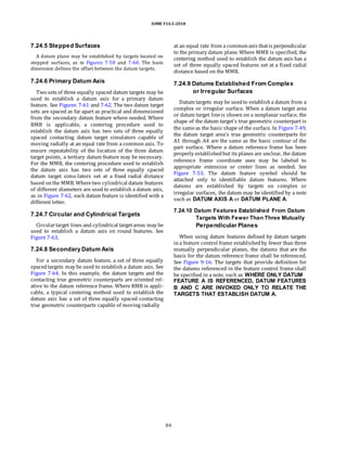
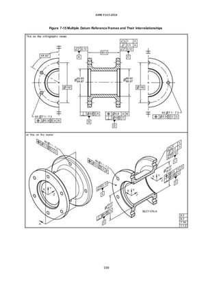
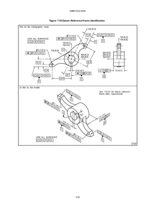
7.21 DATUM REFERENCE FRAME IDENTIFICATION
When a datum reference frame has been properly
estab-lished and it is considered necessary to illustrate
the coor-dinate system of a datum reference frame, the
axes of the coordinate system may be labeled on the
orthographic views to show the translational degrees of
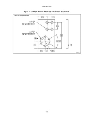
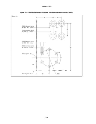
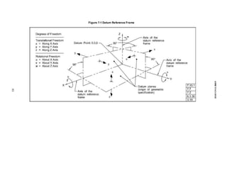
freedom x, y, and z. See Figures 7-2, 7-6, 7-13, and 7-53.
On the model, each datum reference frame shall be
associated with a corresponding coordinate system per
ASME Y14.41.
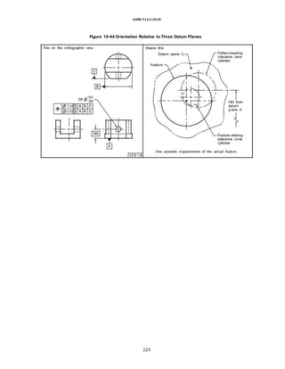
(a) Orthographic View Requirements. When multiple
datum reference frames exist and it is desirable to label the
axes of the coordinate system (X, Y, and Z), any labeled axes
shall include a reference to the associated datum reference
frame. On the orthographic view, the X-, Y-, and Z-axes for
the three datum reference frames shall be identified by the
notation [A,B,C], [A,B,D], and [A,B,E]. These labels
represent the datum features (without modi-fiers) for each
datum reference frame, and follow the X, Y, and Z
identification letters. See Figure 7-54.
(b) Use of Common Datum Features. When common
datum features are used to identify a datum within a
datum reference frame, the relevant common datum
feature letters shall be separated by a hyphen as in [F-
D,B,C].
(c) Model Requirements. Each datum reference frame–
to–coordinate system relationship shall be clearly
presented. When a datum reference frame is labeled, the
label shall take the form of DRF_XXX (underscore
required), where the datum letters of the datum
reference frame are used in place of XXX.
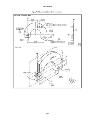
7.22 CUSTOMIZED DATUM REFERENCE
FRAME CONSTRUCTION
To limit the degrees of freedom constrained by datum
features referenced in an order of precedence, a custo-
mized datum reference frame may be invoked. When
applying the customized datum reference frame, the
following requirements govern the constraint on each
datum feature reference:
(a) Where orthographic views are used, the rectan-
gular coordinate axes shall be labeled in at least two
views on the drawing. See Figures 7-55 and 7-56. In a
model, the axes only need to be labeled once for each
datum reference frame.
(b) The degree(s) of freedom to be constrained by
each datum feature referenced in the feature control
frame shall be explicitly stated by placing the designated
degree of freedom to be constrained in lowercase
letter(s) “[x,y,z,u,v,w]” inbrackets followingeach datum
feature reference and any applicable modifier
(s). See Figures 7-56 and 7-57.
NOTE: Customized datum reference frames shall not be used
with composite tolerances. Where a customized datum
reference frame is needed, one or more single-segment feature
control frames shall be used.
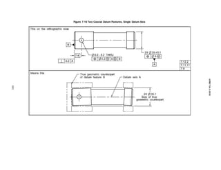
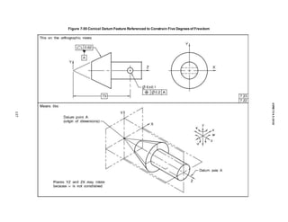
7.23 APPLICATION OF A CUSTOMIZED
DATUM REFERENCE FRAME
In Figure 7-55, the conical primary datum feature A
constrains five degrees of freedom, including translation
inz. The origin of the datum reference frame to locate the
6-dia. hole is from the apex of the conical true geometric
counterpart. In someapplications, it may be necessary to
customize the datum reference frame. The following are
examples of applications of customized datum reference
frames:
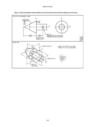
(a) In Figure 7-56, the design intent is that the
primary datum feature A constrains four degrees of
freedom, excluding translation in z. Secondary datum
feature B is a thrust face and, when customized,
constrains the translational degree of freedom (z). The 6-
dia. hole is located to the conical feature with translation
z omitted. Secondary datum feature B constrains transla-
tion in z. In this example, the declared degrees of
constraint for datum feature A are x, y, u, and v. The
declared degree of constraint for datum feature B is z.
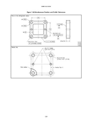
(b) In Figure 7-57, datum feature B would normally
constrain two translational degrees of freedom, x and y,
and one rotational degree of freedom, w. See Figure 7-3,
illustration (f). The purpose of the square hole is to
transfer torque but not to orient the part. Therefore, the
design intent is that datum feature B restrains two
translational degrees of freedom but not the rotational
degree of freedom. In the position tolerance for the three
holes, datum feature A constrains three degrees of
freedom, z, u, and v. Even though datum feature B would
normally constrain the three remaining degrees of
freedom, using the customized datum reference frame
constraintrequirements, datum feature B constrains only
two translational degrees of freedom, x and y. Datum
feature C, then, constrains the remaining degree of
rotational freedom, w.
82](https://image.slidesharecdn.com/asme-y14-220624140424-f03d2f14/85/ASME-Y14-5-2018-Dimensioning-and-Tolerancing-Copy-doc-100-320.jpg)
![ASME Y14.5-2018
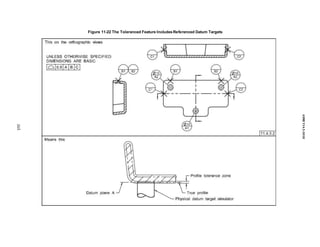
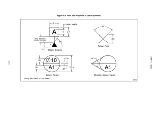
7.24 DATUM TARGETS
Datum targets may be used in establishing a datum
reference frame. Because of inherent irregularities, the
entire surface of somefeatures cannotbe effectively used
to establish a datum. Examples are nonplanar or uneven
surfaces produced by casting, forging, or molding;
surfaces of weldments; and thin-section surfaces subject
to bowing, warping, or other inherent or induced
distortions. Wherethe entire surface is not used to estab-
lish a datum, datum targets are used in establishing a
datum reference frame. Datum targets and datum
features (as described earlier) may be combined to
establish a datum reference frame. Where datum feature
reference is made to datum targets applied on a feature
of size, RMB is applicable unless the datum feature
reference is otherwise modified.
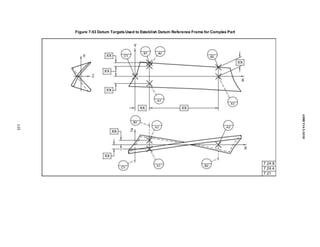
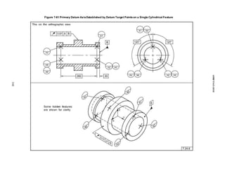
7.24.1 Establishing a Center Plane From
Datum Targets
Figure 7-58 is an example of a center plane established
by a V-shaped true geometric counterpart established
from two datum target lines. In the orthographic view,
datum targets B1 and B2 are located relative to datum
targets A1 and A2 with a basic dimension and are shown
as datum target lines. If a datum target plane V-shaped
true geometric counterpart is required, B1 and B2 would
only be shown in the top view. On the model, the V-
shaped simulator is represented by supple-mental
geometry tangent to the cylindrical feature, and the
datum target is attached by a leader. For clarification, the
directionof movement may be indicated by the addi-tion
of a represented line element as described in ASME
Y14.41.
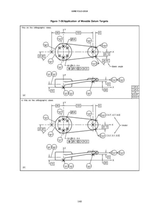
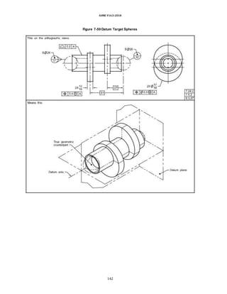
7.24.2 “Movable Datum Target” Symbol
The “movable datum target” symbol may be used to
indicate movement of the datum target’s true geometric
counterpart. Where datum targets establish a center
point, axis, or center plane and RMB is applicable, the
true geometric counterpart moves normal to the true
profile, and the “movable datum target” symbol, though
not required, may be used for clarity. Where the true
geometric counterpart is not normal to the true profile,
the “movabledatum target” symbol shall beused, and the
direction of the movement shall be defined as described
in (a) through (c) below. See Figure 7-58. For an example
of where the true geometric counterpart moves along an
axis, see Figure 7-59.
(a) For orthographic views on engineering drawings,
the movement may be indicated by the addition of a line
indicatingthe directionof movement. The line element is
placed at the point of contact for a datum target point,
along the line for a datum target line, or within the area
for a datum target area. The movement is along the
represented line element. The line element
shall bespecifiedwithone ormore basic angles. See
Figure 7-58, illustration(a).
(b) Alternatively, for drawings that include X-, Y-, and
Z-axes to represent the datum reference frame(s), the
direc-tion of movement may be indicated using a unit
vectordesignationconsistingof i, j, k components (corre-
sponding to the X-, Y-, and Z-axes of the coordinate
system), placed in brackets and adjacent to the “movable
datum target” symbol. The vector direction is toward the
surface of each datum feature. See Figure 7-58,
illustration (b). The vector notation shall be shown in at
least one view where the target is shown. For drawings
that include more than one datum reference frame, the
particular datum reference frame to which the i, j, k
components are related shall be specified by placing the
applicable datum feature letters within square brackets
following the closing bracket that contains the i, j, k
components (such as “[i, j, k]” or [A,B,C]).
(c) For a model, the direction of movement shall be
indicatedby the addition of a represented line element to
indicate the direction of movement. The line element
shall be placed on the outside of the material. One end of
the lineelement shall terminate at the point of contact for
a datum target point, at a point on the line for a datum
target line, or at a point within the area for a datum target
area. The movement is along the represented line
element. See Figure 7-58, illus-tration (c) and ASME
Y14.41.
7.24.3 Datum Target Dimensions
Where applicable, the location and size of datum
targets should be defined with either basic or directly
toleranced dimensions. If basic dimensions are used,
established tooling or gaging tolerances apply. Figure 7-
60 illustrates a part where datum targets are located by
means of basic dimensions.
NOTE: For information on tolerancing physical datum feature
simulators and their interrelationships between the simulators,
see ASME Y14.43.
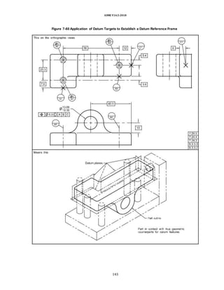
7.24.4 Datum Planes Established by
Datum Targets
A primary datum plane is established by at least three
target points not on a straight line. See Figure 7-60. A
secondary datum plane is usually established by two
targets. A tertiary datum plane is usually established by
one target. A combination of target points, lines, and
areas may be used. See Figure 7-60. For stepped surfaces,
the datum plane should contain at least one of the datum
targets. Some features, such as curved or contoured
surfaces, may require datum planes that are completely
offset from the datum targets. See Figure 7-53.
83](https://image.slidesharecdn.com/asme-y14-220624140424-f03d2f14/85/ASME-Y14-5-2018-Dimensioning-and-Tolerancing-Copy-doc-101-320.jpg)

![ASME Y14.5-2018
Section 10
Tolerances of Position
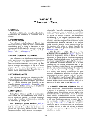
10.1 GENERAL
This Section establishes the principles of tolerances of
locationthrough applicationof positiontolerances. Po s i
t i o n m a y b e u s e d t o c o n t r o l t h e f o l l o w i n g
relationships:
(a) center distancebetween features of sizesuchas
holes, slots, bosses, andtabs
(b) locationof features of size[suchas in (a)] as a
group, from datums
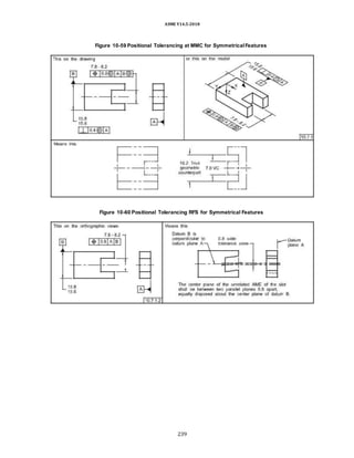
(c) coaxial relationships of features of size
(d) symmetrical relationshipsof features of size
10.2 POSITIONAL TOLERANCING
A positional toleranceestablishes requirements as
explained in(a) and (b) below.
(a) a zone within which the center point, axis, or
center plane of a feature of size is permitted to vary from
a true (theoretically exact) position
(b) (where specified on an MMC or LMC basis) a
boundary, defined as the VC, located at the true (theore-
tically exact) position, that shall not be violated by the
surface or surfaces of the considered feature of size
Basic dimensions establish the true position from
speci-fied datums and between interrelated features. A
posi-tional tolerance shall be indicated by the position
symbol, a tolerance value, applicable material condition
modifiers, and appropriate datum feature references
placed in a feature control frame.
10.2.1 Components of Positional Tolerancing
Paragraphs 10.2.1.1 through 10.2.1.3 describe the
components of positional tolerancing.
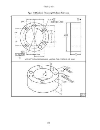
10.2.1.1 Dimensionsfor True Position. Dimensions
used to locate true position shall be basic and defined in
accordance with para. 5.1.1.2. See Figure 10-1. For ap-
plicable notes in digital data files, see ASME Y14.41.
10.2.1.2 Use of Feature Control Frame. A feature
control frame is added to the notation used to specify the
size and number of features. See Figures 10-2 through
10-4, which show different types of feature pattern
dimensioning.
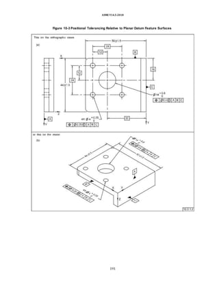
10.2.1.3 Identifying Featuresto Establish Datums.
It is necessary to identify features or features of size on a
part to establish datums for dimensions locating true
posi-tions except where the positioned features establish
the primary datum. (The exception is explained in para.
10.6.2.3.) For example, in Figure 10-2, if datum
references had been omitted, it would not be clear
whether the inside diameter or the outside diameter was
the intended datum feature for the dimensions locating
true positions. The intended datum features are
identifiedwithdatum feature symbols,andthe applicable
datum feature refer-ences are included in the feature
control frame. For infor-mation on specifying datums in
an order of precedence, see subsection 7.10.
10.3 POSITIONAL TOLERANCING
FUNDAMENTALS — I
This subsection is a general explanation of positional
tolerancing.
10.3.1 Material Condition Basis
Positional tolerancingshall beappliedonan MMC, RFS,
or LMC basis. When MMC or LMC is required, the appro-
priate modifier follows the specified tolerance. See
subsection 5.8.
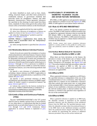
10.3.2 RFS as Related to Positional Tolerancing
The design or function of a part may require the posi-
tional tolerance to be maintained regardless of the
feature’s unrelated AME size. RFS, where applicable to
the positional tolerance associated with a feature of size,
requires the axis, center plane, or center point of each
feature of size to be located within the specified posi-
tional tolerance regardless of the size of the feature. In
Figure 10-5, the sixholes may vary in size from 25 dia. to
25.6 dia. Each hole axis shall be located within the
specifiedpositional toleranceregardless of the size of the
hole.
10.3.3 MMC as Related to Positional Tolerancing
When positional tolerancing at MMC is specified, the
stated positional tolerance applies at the feature size
limit that results in the maximum material in the part.
MMC should be specified in positional tolerancing
179](https://image.slidesharecdn.com/asme-y14-220624140424-f03d2f14/85/ASME-Y14-5-2018-Dimensioning-and-Tolerancing-Copy-doc-197-320.jpg)